在上一篇文章中,讨论了矩阵的工作原理。讨论了如何通过 1 个矩阵和一些神奇的矩阵数学来完成平移、旋转、缩放,甚至从像素到裁剪空间的投影。实现 3D 操作 只需要再向前迈一小步。
在之前的 2D 示例中,将 2D 点 (x, y) 乘以 3x3 矩阵。要实现 3D操作,需要 3D 点 (x, y, z) 和一个 4x4 矩阵。
以最后一个示例为例,将其更改为 3D。我们将再次使用 F,但这次是 3D“F”。
需要做的第一件事是更改顶点着色器以处理 3D。这是旧的顶点着色器。
struct Uniforms {
  color: vec4f,
 // matrix: mat3x3f,
  matrix: mat4x4f,
};

struct Vertex {
 // @location(0) position: vec2f,
  @location(0) position: vec4f,
};

struct VSOutput {
  @builtin(position) position: vec4f,
};

@group(0) @binding(0) var<uniform> uni: Uniforms;

@vertex fn vs(vert: Vertex) -> VSOutput {
  var vsOut: VSOutput;

 // let clipSpace = (uni.matrix * vec3f(vert.position, 1)).xy;
 // vsOut.position = vec4f(clipSpace, 0.0, 1.0);
  vsOut.position = uni.matrix * vert.position;
  return vsOut;
}

@fragment fn fs(vsOut: VSOutput) -> @location(0) vec4f {
  return uni.color;
}
它变得更加简单!就像在 2D 中我们提供 x 和 y 然后将 z 设置为 1,在 3D 中我们将提供 x 、 y 和 z 并且需要 w 为 1 但可以利用属性 w 默认为 1 的事实。
然后需要提供3D数据。
function createFVertices() {
  const vertexData = new Float32Array([
    // left column
    0 , 0  , 0,
    30, 0  , 0,
    0 , 150, 0,
    30, 150, 0,

    // top rung
    30 , 0 , 0,
    100, 0 , 0,
    30 , 30, 0,
    100, 30, 0,

    // middle rung
    30, 60, 0,
    70, 60, 0,
    30, 90, 0,
    70, 90, 0,
  ]);

  const indexData = new Uint32Array([
    0,  1,  2,    2,  1,  3,  // left column
    4,  5,  6,    6,  5,  7,  // top run
    8,  9, 10,   10,  9, 11,  // middle run
  ]);

  return {
    vertexData,
    indexData,
    numVertices: indexData.length,
  };
}
上面只是在每行的末尾添加了一个 0,
const pipeline = device.createRenderPipeline({
    label: '2 attributes',
    layout: 'auto',
    vertex: {
      module,
      entryPoint: 'vs',
      buffers: [
        {
          //arrayStride: (2) * 4, // (2) floats, 4 bytes each
          arrayStride: (3) * 4, // (3) floats, 4 bytes each
          attributes: [
            //{shaderLocation: 0, offset: 0, format: 'float32x2'},  // position
            {shaderLocation: 0, offset: 0, format: 'float32x3'},  // position
          ],
        },
      ],
    },
    fragment: {
      module,
      entryPoint: 'fs',
      targets: [{ format: presentationFormat }],
    },
  });
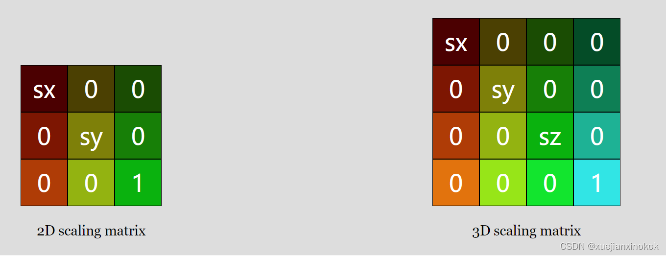
Next we need to change all the matrix math from 2D to 3D
接下来我们需要将所有矩阵数学从 2D 更改为 3D
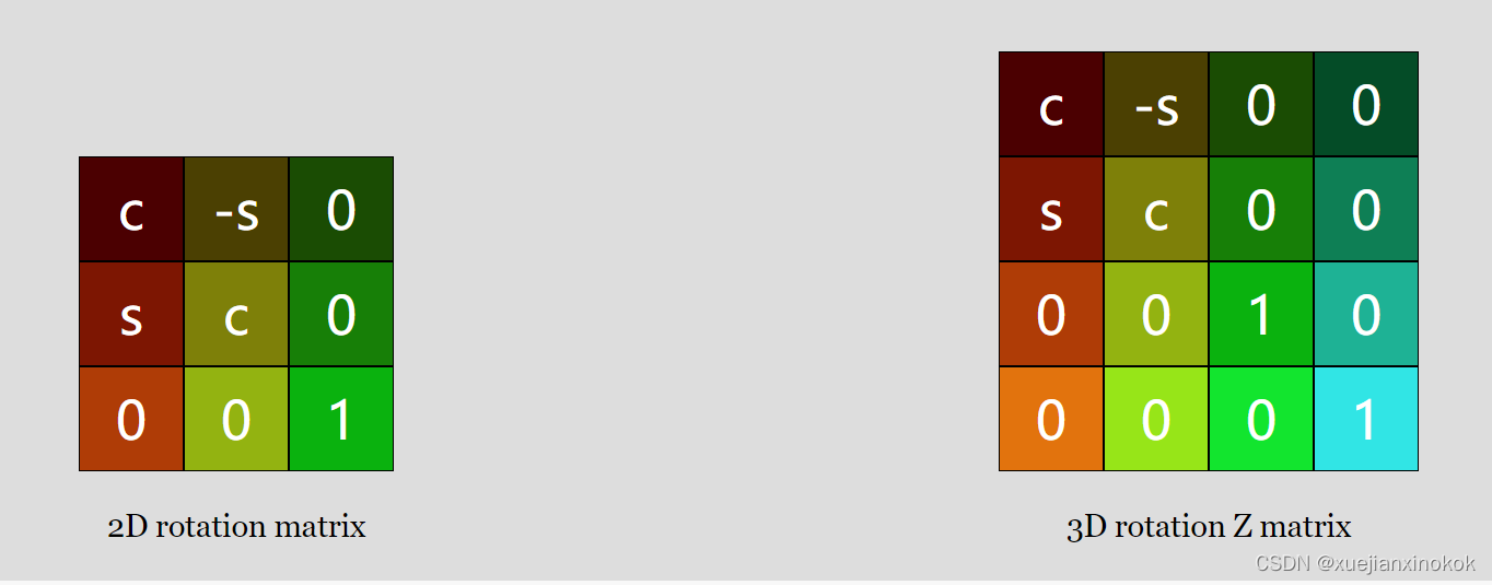
还可以制作 X 和 Y 旋转矩阵
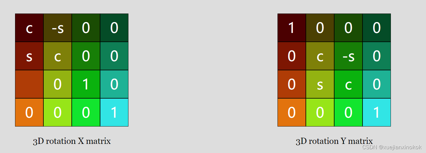
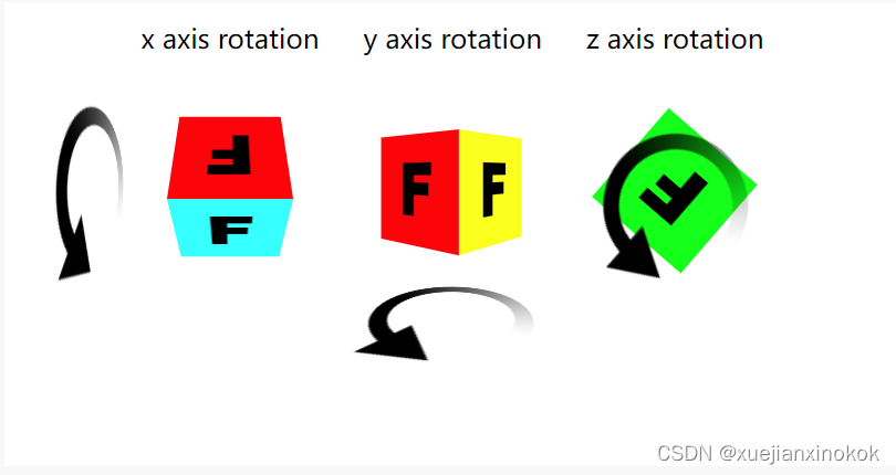
现在有 3 个旋转矩阵。我们只需要一个二维的,因为我们实际上只绕 Z 轴旋转。不过现在,为了制作 3D,我们还希望能够绕 X 轴和 Y 轴旋转。可以看到他们都非常相似。如果我们要解决它们,您会看到它们像以前一样简化
Z轴旋转
newX = x *  c + y * s;
newY = x * -s + y * c;
Y旋转
newX = x *  c + z * s;
newZ = x * -s + z * c;
X旋转
newY = y *  c + z * s;
newZ = y * -s + z * c;
这些旋转如下所示。
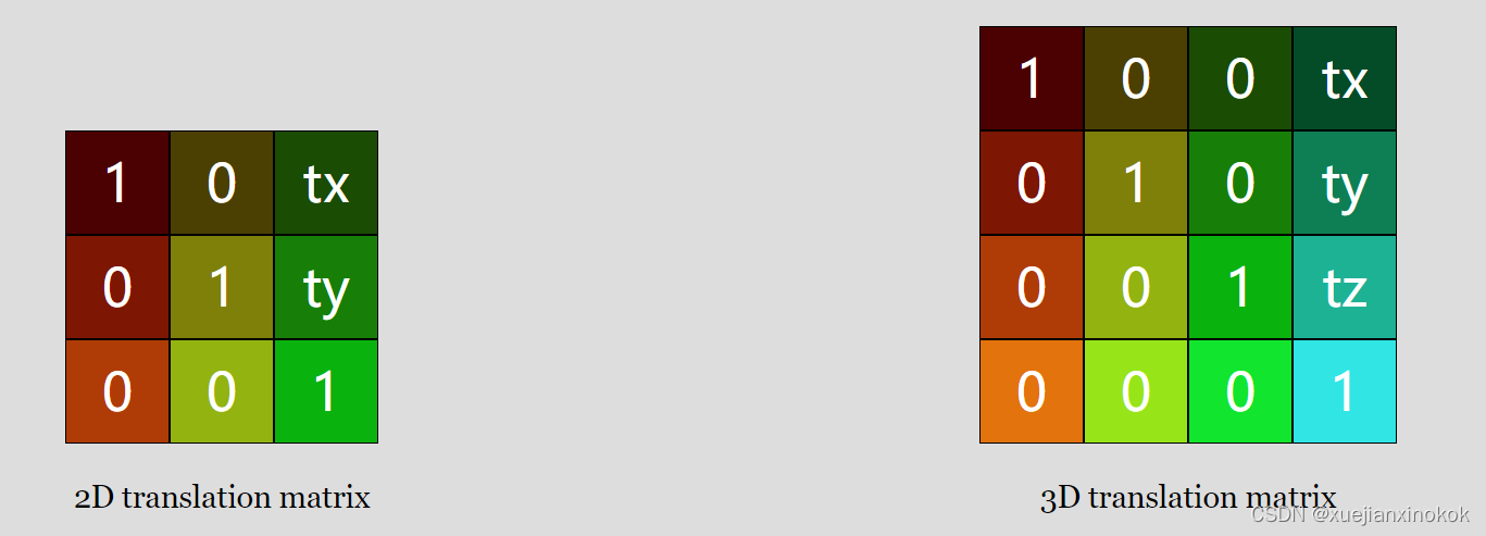
这是 mat3.translation 、 mat3.rotation 和 mat3.scaling 的二维(之前)版本
const mat3 = {
  ...
  translation([tx, ty], dst) {
    dst = dst || new Float32Array(12);
    dst[0] = 1;   dst[1] = 0;   dst[2] = 0;
    dst[4] = 0;   dst[5] = 1;   dst[6] = 0;
    dst[8] = tx;  dst[9] = ty;  dst[10] = 1;
    return dst;
  },

  rotation(angleInRadians, dst) {
    const c = Math.cos(angleInRadians);
    const s = Math.sin(angleInRadians);
    dst = dst || new Float32Array(12);
    dst[0] = c;   dst[1] = s;  dst[2] = 0;
    dst[4] = -s;  dst[5] = c;  dst[6] = 0;
    dst[8] = 0;   dst[9] = 0;  dst[10] = 1;
    return dst;

  },

  scaling([sx, sy], dst) {
    dst = dst || new Float32Array(12);
    dst[0] = sx;  dst[1] = 0;   dst[2] = 0;
    dst[4] = 0;   dst[5] = sy;  dst[6] = 0;
    dst[8] = 0;   dst[9] = 0;   dst[10] = 1;
    return dst;
  },
  ...
这是更新的 3D 版本
const mat4 = {
  ...
  translation([tx, ty, tz], dst) {
    dst = dst || new Float32Array(16);
    dst[ 0] = 1;   dst[ 1] = 0;   dst[ 2] = 0;   dst[ 3] = 0;
    dst[ 4] = 0;   dst[ 5] = 1;   dst[ 6] = 0;   dst[ 7] = 0;
    dst[ 8] = 0;   dst[ 9] = 0;   dst[10] = 1;   dst[11] = 0;
    dst[12] = tx;  dst[13] = ty;  dst[14] = tz;  dst[15] = 1;
    return dst;
  },

  rotationX(angleInRadians, dst) {
    const c = Math.cos(angleInRadians);
    const s = Math.sin(angleInRadians);
    dst = dst || new Float32Array(16);
    dst[ 0] = 1;  dst[ 1] = 0;   dst[ 2] = 0;  dst[ 3] = 0;
    dst[ 4] = 0;  dst[ 5] = c;   dst[ 6] = s;  dst[ 7] = 0;
    dst[ 8] = 0;  dst[ 9] = -s;  dst[10] = c;  dst[11] = 0;
    dst[12] = 0;  dst[13] = 0;   dst[14] = 0;  dst[15] = 1;
    return dst;
  },

  rotationY(angleInRadians, dst) {
    const c = Math.cos(angleInRadians);
    const s = Math.sin(angleInRadians);
    dst = dst || new Float32Array(16);
    dst[ 0] = c;  dst[ 1] = 0;  dst[ 2] = -s;  dst[ 3] = 0;
    dst[ 4] = 0;  dst[ 5] = 1;  dst[ 6] = 0;   dst[ 7] = 0;
    dst[ 8] = s;  dst[ 9] = 0;  dst[10] = c;   dst[11] = 0;
    dst[12] = 0;  dst[13] = 0;  dst[14] = 0;   dst[15] = 1;
    return dst;
  },

  rotationZ(angleInRadians, dst) {
    const c = Math.cos(angleInRadians);
    const s = Math.sin(angleInRadians);
    dst = dst || new Float32Array(16);
    dst[ 0] = c;   dst[ 1] = s;  dst[ 2] = 0;  dst[ 3] = 0;
    dst[ 4] = -s;  dst[ 5] = c;  dst[ 6] = 0;  dst[ 7] = 0;
    dst[ 8] = 0;   dst[ 9] = 0;  dst[10] = 1;  dst[11] = 0;
    dst[12] = 0;   dst[13] = 0;  dst[14] = 0;  dst[15] = 1;
    return dst;
  },

  scaling([sx, sy, sz], dst) {
    dst = dst || new Float32Array(16);
    dst[ 0] = sx;  dst[ 1] = 0;   dst[ 2] = 0;    dst[ 3] = 0;
    dst[ 4] = 0;   dst[ 5] = sy;  dst[ 6] = 0;    dst[ 7] = 0;
    dst[ 8] = 0;   dst[ 9] = 0;   dst[10] = sz;   dst[11] = 0;
    dst[12] = 0;   dst[13] = 0;   dst[14] = 0;    dst[15] = 1;
    return dst;
  },
  ...
同样,我们将制作简化的功能。这是二维的。
 translate(m, translation, dst) {
    return mat3.multiply(m, mat3.translation(translation), dst);
  },

  rotate(m, angleInRadians, dst) {
    return mat3.multiply(m, mat3.rotation(angleInRadians), dst);
  },

  scale(m, scale, dst) {
    return mat3.multiply(m, mat3.scaling(scale), dst);
  },
现在是 3D 的。除了将它们命名为 mat4 并添加另外 2 个旋转函数外,没有太大变化。
  translate(m, translation, dst) {
    return mat4.multiply(m, mat4.translation(translation), dst);
  },

  rotateX(m, angleInRadians, dst) {
    return mat4.multiply(m, mat4.rotationX(angleInRadians), dst);
  },

  rotateY(m, angleInRadians, dst) {
    return mat4.multiply(m, mat4.rotationY(angleInRadians), dst);
  },

  rotateZ(m, angleInRadians, dst) {
    return mat4.multiply(m, mat4.rotationZ(angleInRadians), dst);
  },

  scale(m, scale, dst) {
    return mat4.scaling(m, mat4.scaling(scale), dst);
  },
  ...
现在需要一个 4x4 矩阵乘法函数
 multiply(a, b, dst) {
    dst = dst || new Float32Array(16);
    const b00 = b[0 * 4 + 0];
    const b01 = b[0 * 4 + 1];
    const b02 = b[0 * 4 + 2];
    const b03 = b[0 * 4 + 3];
    const b10 = b[1 * 4 + 0];
    const b11 = b[1 * 4 + 1];
    const b12 = b[1 * 4 + 2];
    const b13 = b[1 * 4 + 3];
    const b20 = b[2 * 4 + 0];
    const b21 = b[2 * 4 + 1];
    const b22 = b[2 * 4 + 2];
    const b23 = b[2 * 4 + 3];
    const b30 = b[3 * 4 + 0];
    const b31 = b[3 * 4 + 1];
    const b32 = b[3 * 4 + 2];
    const b33 = b[3 * 4 + 3];
    const a00 = a[0 * 4 + 0];
    const a01 = a[0 * 4 + 1];
    const a02 = a[0 * 4 + 2];
    const a03 = a[0 * 4 + 3];
    const a10 = a[1 * 4 + 0];
    const a11 = a[1 * 4 + 1];
    const a12 = a[1 * 4 + 2];
    const a13 = a[1 * 4 + 3];
    const a20 = a[2 * 4 + 0];
    const a21 = a[2 * 4 + 1];
    const a22 = a[2 * 4 + 2];
    const a23 = a[2 * 4 + 3];
    const a30 = a[3 * 4 + 0];
    const a31 = a[3 * 4 + 1];
    const a32 = a[3 * 4 + 2];
    const a33 = a[3 * 4 + 3];

    dst[0] = b00 * a00 + b01 * a10 + b02 * a20 + b03 * a30;
    dst[1] = b00 * a01 + b01 * a11 + b02 * a21 + b03 * a31;
    dst[2] = b00 * a02 + b01 * a12 + b02 * a22 + b03 * a32;
    dst[3] = b00 * a03 + b01 * a13 + b02 * a23 + b03 * a33;

    dst[4] = b10 * a00 + b11 * a10 + b12 * a20 + b13 * a30;
    dst[5] = b10 * a01 + b11 * a11 + b12 * a21 + b13 * a31;
    dst[6] = b10 * a02 + b11 * a12 + b12 * a22 + b13 * a32;
    dst[7] = b10 * a03 + b11 * a13 + b12 * a23 + b13 * a33;

    dst[8] = b20 * a00 + b21 * a10 + b22 * a20 + b23 * a30;
    dst[9] = b20 * a01 + b21 * a11 + b22 * a21 + b23 * a31;
    dst[10] = b20 * a02 + b21 * a12 + b22 * a22 + b23 * a32;
    dst[11] = b20 * a03 + b21 * a13 + b22 * a23 + b23 * a33;

    dst[12] = b30 * a00 + b31 * a10 + b32 * a20 + b33 * a30;
    dst[13] = b30 * a01 + b31 * a11 + b32 * a21 + b33 * a31;
    dst[14] = b30 * a02 + b31 * a12 + b32 * a22 + b33 * a32;
    dst[15] = b30 * a03 + b31 * a13 + b32 * a23 + b33 * a33;

    return dst;
  },
还需要更新投影功能。这是旧的
 projection(width, height, dst) {
    // Note: This matrix flips the Y axis so that 0 is at the top.
    dst = dst || new Float32Array(12);
    dst[0] = 2 / width;  dst[1] = 0;             dst[2] = 0;
    dst[4] = 0;          dst[5] = -2 / height;   dst[6] = 0;
    dst[8] = -1;         dst[9] = 1;             dst[10] = 1;
    return dst;
  },
从像素转换为裁剪空间。我们第一次尝试将它扩展到 3D 让我们试试
 projection(width, height, depth, dst) {
    // Note: This matrix flips the Y axis so that 0 is at the top.
    dst = dst || new Float32Array(16);
    dst[ 0] = 2 / width;  dst[ 1] = 0;            dst[ 2] = 0;          dst[ 3] = 0;
    dst[ 4] = 0;          dst[ 5] = -2 / height;  dst[ 6] = 0;          dst[ 7] = 0;
    dst[ 8] = 0;          dst[ 9] = 0;            dst[10] = 2 / depth;  dst[11] = 0;
    dst[12] = -1;         dst[13] = 1;            dst[14] = 1;          dst[15] = 1;
    return dst;
  },
Just like we needed to convert from pixels to clip space for X and Y, for Z we need to do the same thing. In this case we making the Z axis “pixel units” as well?. We’ll pass in some value similar to width for the depth so our space will be 0 to width pixels wide, 0 to height pixels tall, but for depth it will be -depth / 2 to +depth / 2.
就像我们需要将 X 和 Y 的像素空间转换为裁剪空间一样,对于 Z,我们也需要做同样的事情。在这种情况下,我们也将 Z 轴设为“单位像素”吗?我们将为 depth 传递一些类似于 width 的值,因此我们的空间将为 0 到 width 像素宽,0 到 height 像素高,但对于 depth 它将是 -depth / 2 到 +depth / 2 。
我们需要在uniforms中提供一个 4x4 矩阵
 // color, matrix
 // const uniformBufferSize = (4 + 12) * 4;
  const uniformBufferSize = (4 + 16) * 4;
  const uniformBuffer = device.createBuffer({
    label: 'uniforms',
    size: uniformBufferSize,
    usage: GPUBufferUsage.UNIFORM | GPUBufferUsage.COPY_DST,
  });

  const uniformValues = new Float32Array(uniformBufferSize / 4);

  // offsets to the various uniform values in float32 indices
  const kColorOffset = 0;
  const kMatrixOffset = 4;

  const colorValue = uniformValues.subarray(kColorOffset, kColorOffset + 4);
  //const matrixValue = uniformValues.subarray(kMatrixOffset, kMatrixOffset + 12);
  const matrixValue = uniformValues.subarray(kMatrixOffset, kMatrixOffset + 16);
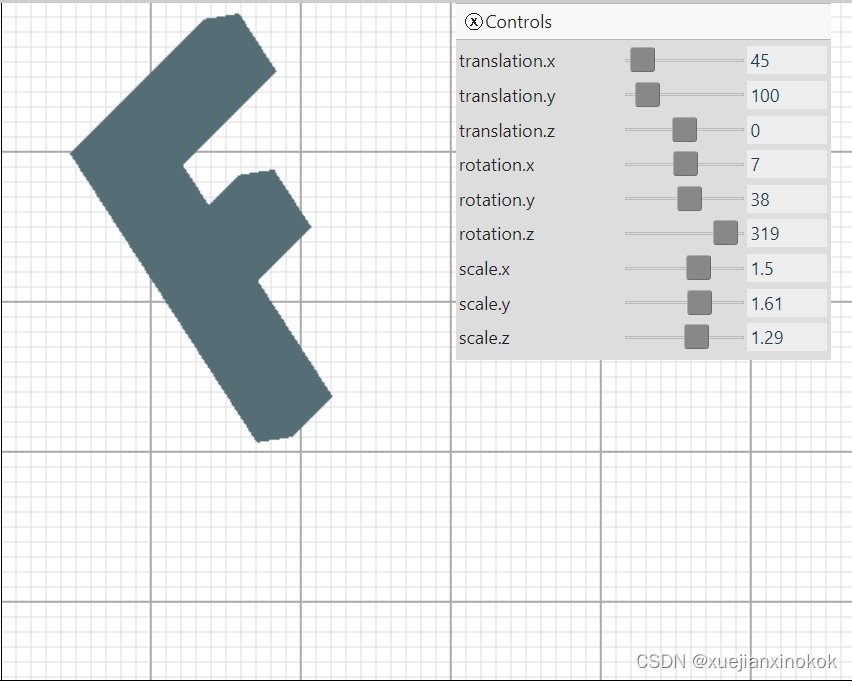
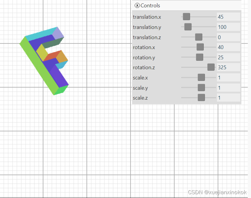
需要更新计算矩阵的代码。
const settings = {
   // translation: [150, 100],
   // rotation: degToRad(30),
   // scale: [1, 1],
    translation: [45, 100, 0],
    rotation: [degToRad(40), degToRad(25), degToRad(325)],
    scale: [1, 1, 1],
  };

  ...

  function render() {
    ...

   // mat3.projection(canvas.clientWidth, canvas.clientHeight, matrixValue);
   // mat3.translate(matrixValue, settings.translation, matrixValue);
   // mat3.rotate(matrixValue, settings.rotation, matrixValue);
   // mat3.scale(matrixValue, settings.scale, matrixValue);
    mat4.projection(canvas.clientWidth, canvas.clientHeight, 400, matrixValue);
    mat4.translate(matrixValue, settings.translation, matrixValue);
    mat4.rotateX(matrixValue, settings.rotation[0], matrixValue);
    mat4.rotateY(matrixValue, settings.rotation[1], matrixValue);
    mat4.rotateZ(matrixValue, settings.rotation[2], matrixValue);
    mat4.scale(matrixValue, settings.scale, matrixValue);
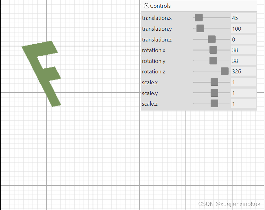
遇到的第一个问题是现在的数据是平面 F,这使得很难看到任何 3D。为了解决这个问题,将数据扩展到 3D。当前的 F 由 3 个矩形组成,每个矩形有 2 个三角形。要使其成为 3D,总共需要 16 个矩形。正面有 3 个矩形,背面有 3 个,左侧有 1 个,右侧有 4 个,顶部有 2 个,底部有 3 个。
只需要获取所有当前顶点位置并复制它们,但将它们移动到 Z 中。然后将它们与索引连接起来
function createFVertices() {
  const vertexData = new Float32Array([
    // left column
    0, 0, 0,
    30, 0, 0,
    0, 150, 0,
    30, 150, 0,

    // top rung
    30, 0, 0,
    100, 0, 0,
    30, 30, 0,
    100, 30, 0,

    // middle rung
    30, 60, 0,
    70, 60, 0,
    30, 90, 0,
    70, 90, 0,

    // left column back
    0, 0, 30,
    30, 0, 30,
    0, 150, 30,
    30, 150, 30,

    // top rung back
    30, 0, 30,
    100, 0, 30,
    30, 30, 30,
    100, 30, 30,

    // middle rung back
    30, 60, 30,
    70, 60, 30,
    30, 90, 30,
    70, 90, 30,
  ]);

  const indexData = new Uint32Array([
    // front
    0,  1,  2,    2,  1,  3,  // left column
    4,  5,  6,    6,  5,  7,  // top run
    8,  9, 10,   10,  9, 11,  // middle run

    // back
    12,  13,  14,   14, 13, 15,  // left column back
    16,  17,  18,   18, 17, 19,  // top run back
    20,  21,  22,   22, 21, 23,  // middle run back

    0, 5, 12,   12, 5, 17,   // top
    0, 12, 2,   12, 2, 14,   // left
    2, 3, 14,   14, 3, 15,   // bottom
    5, 7, 17,   17, 7, 19,   // top rung right
    6, 7, 18,   18, 7, 19,   // top rung bottom
    6, 8, 18,   18, 8, 20,   // between top and middle rung
    8, 9, 20,   20, 9, 21,   // middle rung top
    9, 11, 21,  21, 11, 23,  // middle rung right
    10, 11, 22, 22, 11, 23,  // middle rung bottom
    10, 3, 22,  22, 3, 15,   // stem right
  ]);

  return {
    vertexData,
    indexData,
    numVertices: indexData.length,
  };
}
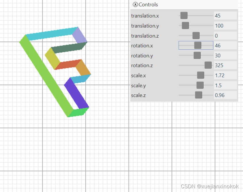
效果如下所示:
移动滑块很难判断它是 3D 的。尝试为每个矩形着色不同的颜色。为此,将向顶点着色器添加另一个属性,并通过阶段间变量将其从顶点着色器传递到片段着色器。
首先更新着色器
struct Uniforms {
  //color: vec4f,
  matrix: mat4x4f,
};

struct Vertex {
  @location(0) position: vec4f,
  @location(1) color: vec4f,//here
};

struct VSOutput {
  @builtin(position) position: vec4f,
  @location(0) color: vec4f, //here
};

@group(0) @binding(0) var<uniform> uni: Uniforms;

@vertex fn vs(vert: Vertex) -> VSOutput {
  var vsOut: VSOutput;
  vsOut.position = uni.matrix * vert.position;
  vsOut.color = vert.color; //here
  return vsOut;
}

@fragment fn fs(vsOut: VSOutput) -> @location(0) vec4f {
  //return uni.color;
  return vsOut.color;
}
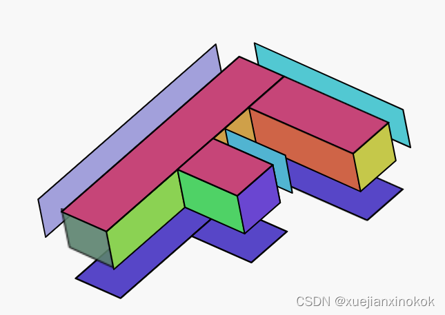
需要为顶点数据添加颜色,但是有一个问题。目前使用索引来共享顶点。但是,如果想为每个面绘制不同的颜色,这些顶点就不能共享,因为它们每个只能获得一种颜色。
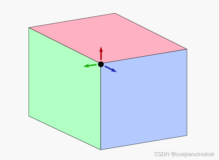
上面的角顶点需要为它共享的 3 个面中的每一个使用一次,但每次都需要不同的颜色,因此使用索引是有问题的。 [注释1]
因此,将数据从索引扩展到非索引,同时将添加顶点颜色,以便 F 的每个部分都获得不同的颜色。
function createFVertices() {
  //const vertexData = new Float32Array([
  const positions = [
    // left column
    0, 0, 0,
    30, 0, 0,
    0, 150, 0,
    30, 150, 0,

    // top rung
    30, 0, 0,
    100, 0, 0,
    30, 30, 0,
    100, 30, 0,

    // middle rung
    30, 60, 0,
    70, 60, 0,
    30, 90, 0,
    70, 90, 0,

    // left column back
    0, 0, 30,
    30, 0, 30,
    0, 150, 30,
    30, 150, 30,

    // top rung back
    30, 0, 30,
    100, 0, 30,
    30, 30, 30,
    100, 30, 30,

    // middle rung back
    30, 60, 30,
    70, 60, 30,
    30, 90, 30,
    70, 90, 30,
 // ]);
  ];

 // const indexData = new Uint32Array([
  const indices = [
    // front
    0,  1,  2,    2,  1,  3,  // left column
    4,  5,  6,    6,  5,  7,  // top run
    8,  9, 10,   10,  9, 11,  // middle run

    // back
    12,  13,  14,   14, 13, 15,  // left column back
    16,  17,  18,   18, 17, 19,  // top run back
    20,  21,  22,   22, 21, 23,  // middle run back

    0, 5, 12,   12, 5, 17,   // top
    0, 12, 2,   12, 2, 14,   // left
    2, 3, 14,   14, 3, 15,   // bottom
    5, 7, 17,   17, 7, 19,   // top rung right
    6, 7, 18,   18, 7, 19,   // top rung bottom
    6, 8, 18,   18, 8, 20,   // between top and middle rung
    8, 9, 20,   20, 9, 21,   // middle rung top
    9, 11, 21,  21, 11, 23,  // middle rung right
    10, 11, 22, 22, 11, 23,  // middle rung bottom
    10, 3, 22,  22, 3, 15,   // stem right
 // ]);
  ];

  const quadColors = [
      200,  70, 120,  // left column front
      200,  70, 120,  // top rung front
      200,  70, 120,  // middle rung front
       80,  70, 200,  // left column back
       80,  70, 200,  // top rung back
       80,  70, 200,  // middle rung back
       70, 200, 210,  // top
      160, 160, 220,  // left side
       90, 130, 110,  // bottom
      200, 200,  70,  // top rung right
      210, 100,  70,  // under top rung
      210, 160,  70,  // between top rung and middle
       70, 180, 210,  // top of middle rung
      100,  70, 210,  // right of middle rung
       76, 210, 100,  // bottom of middle rung.
      140, 210,  80,  // right of bottom
  ];

  const numVertices = indices.length;
  const vertexData = new Float32Array(numVertices * 4); // xyz + color
  const colorData = new Uint8Array(vertexData.buffer);

  for (let i = 0; i < indices.length; ++i) {
    const positionNdx = indices[i] * 3;
    const position = positions.slice(positionNdx, positionNdx + 3);
    vertexData.set(position, i * 4);

    const quadNdx = (i / 6 | 0) * 3;
    const color = quadColors.slice(quadNdx, quadNdx + 3);
    colorData.set(color, i * 16 + 12);  // set RGB
    colorData[i * 16 + 15] = 255;       // set A
  }

  return {
    vertexData,
   // indexData,
   // numVertices: indexData.length,
    numVertices,
  };
}
遍历每个索引,获取该索引的位置并将位置值放入 vertexData 。对与 colorData 相同的数据有一个单独的视图,因此通过四边形索引(每 6 个顶点一个四边形)提取颜色,并为该四边形的每个顶点插入相同的颜色。数据最终会变成这样。
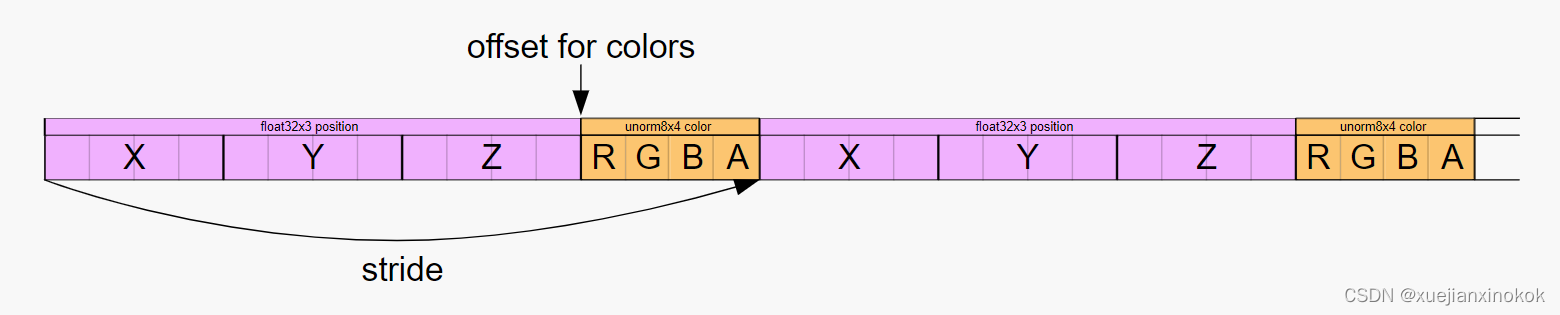
我们添加的颜色是无符号字节,值从 0 到 255,类似于 css rgb() 颜色。通过将管线中的属性类型设置为 unorm8x4 (无符号规范化 8 位值 x 4),GPU 会将值从缓冲区中拉出并在将它们提供给着色器时对其进行规范化。这意味着它将使它们从 0 变为 1,在本例中是将它们除以 255。
现在我们有了数据,需要更改管线以使用它。
const pipeline = device.createRenderPipeline({
    label: '2 attributes',
    layout: 'auto',
    vertex: {
      module,
      entryPoint: 'vs',
      buffers: [
        {
          //arrayStride: (3) * 4, // (3) floats, 4 bytes each
          arrayStride: (4) * 4, // (3) floats 4 bytes each + one 4 byte color
          attributes: [
            {shaderLocation: 0, offset: 0, format: 'float32x3'},  // position
            {shaderLocation: 1, offset: 12, format: 'unorm8x4'},  // color
          ],
        },
      ],
    },
    fragment: {
      module,
      entryPoint: 'fs',
      targets: [{ format: presentationFormat }],
    },
  });
不再需要制作索引缓冲区。
  // const { vertexData, indexData, numVertices } = createFVertices();
  const { vertexData, numVertices } = createFVertices();
  const vertexBuffer = device.createBuffer({
    label: 'vertex buffer vertices',
    size: vertexData.byteLength,
    usage: GPUBufferUsage.VERTEX | GPUBufferUsage.COPY_DST,
  });
  device.queue.writeBuffer(vertexBuffer, 0, vertexData);
 // const indexBuffer = device.createBuffer({
 //   label: 'index buffer',
 //   size: indexData.byteLength,
 //   usage: GPUBufferUsage.INDEX | GPUBufferUsage.COPY_DST,
 // });
 // device.queue.writeBuffer(indexBuffer, 0, indexData);
hide deleted
and we need to draw without indices
我们需要在没有索引的情况下绘制
 function render() {
    ...
    pass.setPipeline(pipeline);
    pass.setVertexBuffer(0, vertexBuffer);
   // pass.setIndexBuffer(indexBuffer, 'uint32');

    ...

    pass.setBindGroup(0, bindGroup);
  //  pass.drawIndexed(numVertices);
    pass.draw(numVertices);

    ...
  }
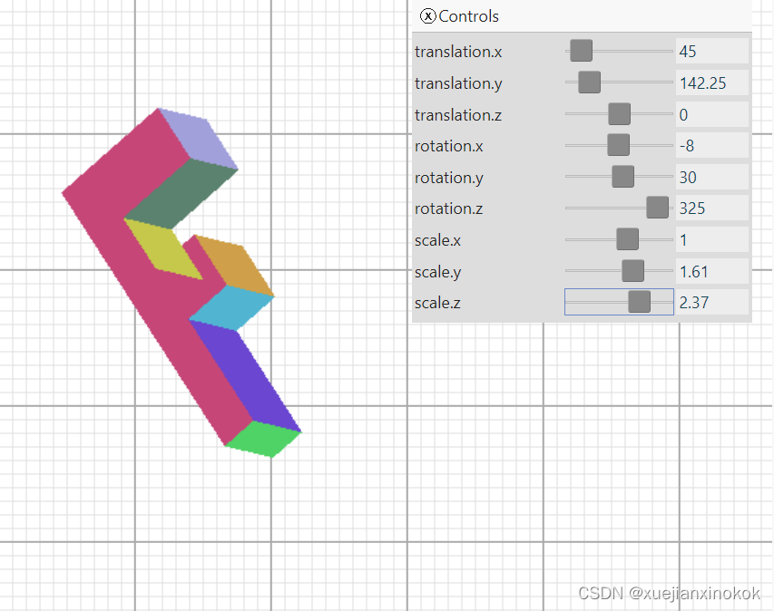
现在效果如下。
Uh oh, what’s that mess? Well, it turns out all the various parts of that 3D ‘F’, front, back, sides, etc get drawn in the order they appear in our geometry data. That doesn’t give us quite the desired results as sometimes the ones in the back get drawn after the ones in the front.
哦,那是什么烂摊子?好吧,事实证明 3D “F”的所有不同部分,正面、背面、侧面等都是按照它们在我们的几何数据中出现的顺序绘制的。这并没有带来非常理想的结果,因为有时后面的那些会在前面的那些之后被绘制。
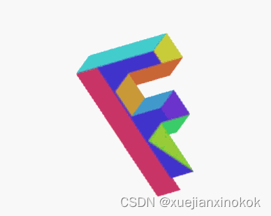
红色部分是“F”的前面,但因为它是数据的第一部分,所以它先被绘制,然后它后面的其他三角形被绘制,覆盖它。例如,紫色部分实际上是“F”的背面。它排在第二位,因为它在我们的数据中排在第二位。
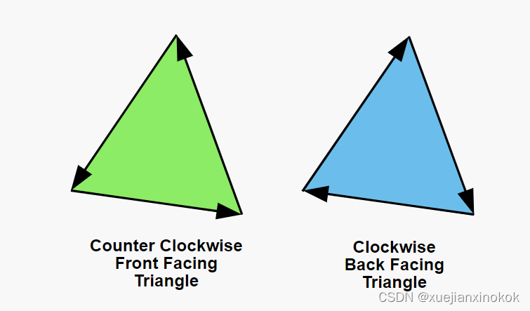
Triangles in WebGPU have the concept of front facing and back facing. By default a front facing triangle has its vertices go in a counter clockwise direction in clip space. A back facing triangle has its vertices go in a clockwise direction in clip space.
WebGPU 中的三角形有前向和后向的概念。默认情况下,正面三角形的顶点在裁剪空间中沿逆时针方向移动。背面三角形的顶点在裁剪空间中沿顺时针方向移动。
The gpu has the ability to draw only forward facing or only back facing triangles. We can turn that feature on by modifying the pipeline
gpu 能够只绘制向前或后向三角形。我们可以通过修改管道来打开该功能
 const pipeline = device.createRenderPipeline({
    label: '2 attributes',
    layout: 'auto',
    vertex: {
      module,
      entryPoint: 'vs',
      buffers: [
        {
          arrayStride: (4) * 4, // (3) floats 4 bytes each + one 4 byte color
          attributes: [
            {shaderLocation: 0, offset: 0, format: 'float32x3'},  // position
            {shaderLocation: 1, offset: 12, format: 'unorm8x4'},  // color
          ],
        },
      ],
    },
    fragment: {
      module,
      entryPoint: 'fs',
      targets: [{ format: presentationFormat }],
    },
    primitive: {
      cullMode: 'back', //here
    },
  });
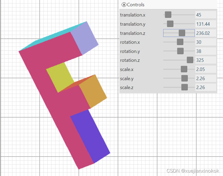
With cullMode set to back, “back facing” triangles will be culled. “Culling” in this case is a fancy word for “not drawing”. So, with cullMode set to ‘back’, this is what we get
当 cullMode 设置为 back 时,“背面(back facing)”三角形将被剔除。在这种情况下,“剔除”是“不绘制”的奇特词。所以,将 cullMode 设置为 ‘back’ ,这就是我们得到的
Hey! Where did all the triangles go? It turns out, many of them are facing the wrong way. Rotate it and you’ll see them appear when you look at the other side. Fortunately it’s easy to fix. We just look at which ones are backward and exchange 2 of their vertices. For example if one backward triangle has indices
嘿!所有的三角形都去哪儿了?事实证明,他们中的许多人正面临着错误的道路。旋转它,当您看向另一侧时,您会看到它们出现。幸运的是,它很容易修复。我们只是看看哪些是向后的,并交换他们的 2 个顶点。例如,如果一个向后三角形有索引
6, 7, 8,
我们可以交换其中的两个让他们走另一条路
6, 8, 7,
Importantly, as far as WebGPU is concerned, whether or not a triangle is considered to be going clockwise or counter clockwise depends on the vertices of that triangle in clip space. In other words, WebGPU figures out whether a triangle is front or back AFTER you’ve applied math to the vertices in the vertex shader. That means for example, a clockwise triangle that is scaled in X by -1 becomes a counter clockwise triangle or, a clockwise triangle rotated 180 degrees becomes a counter clockwise triangle. Because we didn’t set cullMode before, we could see both clockwise(front) and counter clockwise(back) facing triangles. Now that we’ve set cullMode to back, any time a front facing triangle flips around, either because of scaling or rotation or for whatever reason, WebGPU won’t draw it. That’s a good thing since, as you turn something around in 3D, you generally want whichever triangles are facing you to be considered front facing.
重要的是,就 WebGPU 而言,三角形是顺时针还是逆时针取决于裁剪空间中该三角形的顶点。换句话说,WebGPU 会在您对顶点着色器中的顶点应用数学运算后计算出三角形是正面还是背面。这意味着,例如,在 X 中按 -1 缩放的顺时针三角形变为逆时针三角形,或者旋转 180 度的顺时针三角形变为逆时针三角形。因为我们之前没有设置 cullMode ,所以我们可以看到顺时针(正面)和逆时针(背面)的三角形。现在我们已经将 cullMode 设置为 back ,任何时候因为缩放或旋转或出于任何原因,前面的三角形翻转,WebGPU 都不会绘制它。这是一件好事,因为当您在 3D 中旋转某物时,您通常希望面向您的任何三角形都被视为正面。
BUT! Remember that in clip space +Y is at the top, but in our pixel space +Y is at the bottom. In other words, our matrix is flipping all the triangles vertically. This means that in order to draw things with +Y at the bottom we either need to set cullMode to ‘front’, OR flip all our triangles vertices. Let’s set cullMode to ‘front’ and then also fix the vertex data so all the triangles have the same direction.
但!请记住,在裁剪空间中 +Y 位于顶部,但在我们的像素空间中 +Y 位于底部。换句话说,我们的矩阵垂直翻转所有三角形。这意味着为了在底部绘制带有 +Y 的东西,我们需要将 cullMode 设置为 ‘front’ ,或者翻转所有三角形顶点。让我们将 cullMode 设置为 ‘front’ ,然后固定顶点数据,使所有三角形都具有相同的方向。
const indices = [
    // front
    0,  1,  2,    2,  1,  3,  // left column
    4,  5,  6,    6,  5,  7,  // top run
    8,  9, 10,   10,  9, 11,  // middle run

    // back
    //12,  13,  14,   14, 13, 15,  // left column back
    12,  14,  13,   14, 15, 13,  // left column back
    //16,  17,  18,   18, 17, 19,  // top run back
    16,  18,  17,   18, 19, 17,  // top run back
    //20,  21,  22,   22, 21, 23,  // middle run back
    20,  22,  21,   22, 23, 21,  // middle run back

    //0, 5, 12,   12, 5, 17,   // top
    0, 12, 5,   12, 17, 5,   // top
    //5, 7, 17,   17, 7, 19,   // top rung right
    5, 17, 7,   17, 19, 7,   // top rung right
    6, 7, 18,   18, 7, 19,   // top rung bottom
    //6, 8, 18,   18, 8, 20,   // between top and middle rung
    6, 18, 8,   18, 20, 8,   // between top and middle rung
    //8, 9, 20,   20, 9, 21,   // middle rung top
    8, 20, 9,   20, 21, 9,   // middle rung top
    //9, 11, 21,  21, 11, 23,  // middle rung right
    9, 21, 11,  21, 23, 11,  // middle rung right
    10, 11, 22, 22, 11, 23,  // middle rung bottom
    //10, 3, 22,  22, 3, 15,   // stem right
    10, 22, 3,  22, 15, 3,   // stem right
    2, 3, 14,   14, 3, 15,   // bottom
    0, 2, 12,   12, 2, 14,   // left
  ];
const pipeline = device.createRenderPipeline({
    ...
    primitive: {
      // cullMode: 'back',
      cullMode: 'front',
    },
  });
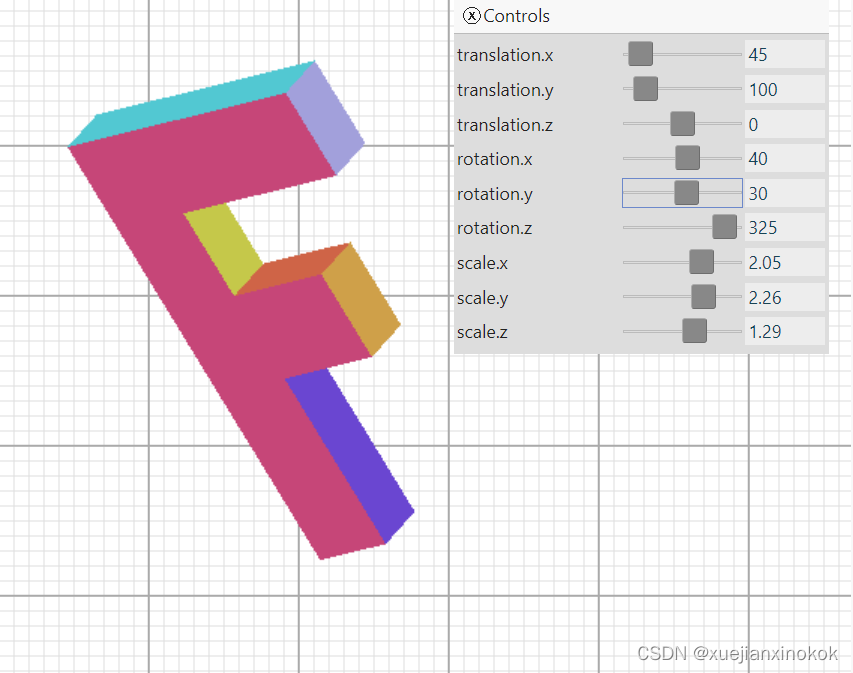
有了这些变化,让所有的三角形都面向一个方向,我们就可以做到这一点
That’s closer but there’s still one more problem. Even with all the triangles facing in the correct direction, and with the ones facing away from us being culled, we still have places where triangles that should be in the back are being drawn over triangles that should be in front.
这更接近了,但还有一个问题。即使所有的三角形都朝向正确的方向,并且背对我们的三角形被剔除,仍然有一些地方应该在后面的三角形被绘制在应该在前面的三角形上。
应用“深度纹理” (Enter “Depth Textures” )
A depth texture, sometimes called a depth-buffer or Z-Buffer, is a rectangle of depth texels, one depth texel for each color texel in the texture we’re drawing to. If we create and bind a depth texture, then, as WebGPU draws each pixel it can also draw a depth pixel. It does this based on the values we return from the vertex shader for Z. Just like we had to convert to clip space for X and Y, Z is also in clip space. For Z, clip space is 0 to +1.
深度纹理,有时称为深度缓冲区或 Z 缓冲区,是一个矩形的深度纹素,一个深度纹素对应我们正在绘制的纹理中的每个颜色纹素。如果我们创建并绑定一个深度纹理,那么,当 WebGPU 绘制每个像素时,它也可以绘制一个深度像素。它根据我们从 Z 的顶点着色器返回的值来执行此操作。就像我们必须为 X 和 Y 转换到裁剪空间一样,Z 也在裁剪空间中。对于 Z,剪辑空间为 0 到 +1。
Before WebGPU draws a color pixel it will check the corresponding depth pixel. If the depth (Z) value for the pixel it’s about to draw does not match some condition relative to the value of the corresponding depth pixel. then WebGPU will not draw the new color pixel. Otherwise it draws both the new color pixel with the color from your fragment shader AND it draws the depth pixel with the new depth value. This means, pixels that are behind other pixels won’t get drawn.
在 WebGPU 绘制颜色像素之前,它会检查相应的深度像素。如果要绘制的像素的深度 (Z) 值与相应深度像素的值相关的某些条件不匹配。那么 WebGPU 将不会绘制新的颜色像素。否则,它会使用片段着色器中的颜色绘制新的颜色像素,并使用新的深度值绘制深度像素。这意味着,不会绘制位于其他像素后面的像素。
要设置和使用深度纹理,需要更新管线
 const pipeline = device.createRenderPipeline({
    label: '2 attributes',
    layout: 'auto',
    vertex: {
      module,
      entryPoint: 'vs',
      buffers: [
        {
          arrayStride: (4) * 4, // (3) floats 4 bytes each + one 4 byte color
          attributes: [
            {shaderLocation: 0, offset: 0, format: 'float32x3'},  // position
            {shaderLocation: 1, offset: 12, format: 'unorm8x4'},  // color
          ],
        },
      ],
    },
    fragment: {
      module,
      entryPoint: 'fs',
      targets: [{ format: presentationFormat }],
    },
    primitive: {
      cullMode: 'front',
    },
    depthStencil: { //here
      depthWriteEnabled: true, //here
      depthCompare: 'less', //here
      format: 'depth24plus', //here
    },
  });
Above we’re setting depthCompare: 'less'. This means, only draw the new pixel, if the Z value for the new pixel is “less” than the corresponding pixel in the depth texture. other options include never, equal, less-equal, greater, not-equal, greater-equal, always.
上面我们设置了 depthCompare: 'less' 。这意味着,如果新像素的 Z 值“小于”深度纹理中的相应像素,则只绘制新像素。其他选项包括 never 、 equal 、 less-equal 、 greater 、 not-equal 、 greater-equal 、 always 。
depthWriteEnabled: true means, if we pass the depthCompare test, then write the Z value of our new pixel to the depth texture. In our case, this means each time a pixel we’re drawing has a Z value less than what’s already in the depth texture, we’ll draw that pixel and update the depth texture. In this way, if we later try to draw a pixel that’s further back (has a higher Z value) it will not be draw.
depthWriteEnabled: true 表示,如果我们通过了 depthCompare 测试,则将新像素的 Z 值写入深度纹理。在我们的例子中,这意味着每当我们绘制的像素的 Z 值小于深度纹理中已有的值时,我们将绘制该像素并更新深度纹理。这样,如果我们稍后尝试绘制更靠后的像素(具有更高的 Z 值),它将不会被绘制。
format is similar to fragment.targets[?].format. It’s the format of the depth texture we will use. The available depth texture formats were listed in the article on textures. depth24plus is a good default format to choose.
format 类似于 fragment.targets[?].format 。这是我们将使用的深度纹理的格式。有关纹理的文章中列出了可用的深度纹理格式。 depth24plus 是一个很好的默认格式可供选择。
我们还需要更新渲染过程描述符,使其具有深度模板附件。
const renderPassDescriptor = {
    label: 'our basic canvas renderPass',
    colorAttachments: [
      {
        // view: <- to be filled out when we render
        loadOp: 'clear',
        storeOp: 'store',
      },
    ],
    depthStencilAttachment: {
      // view: <- to be filled out when we render
      depthClearValue: 1.0,
      depthLoadOp: 'clear',
      depthStoreOp: 'store',
    },
  };
Depth values generally go from 0.0 to 1.0. We set depthClearValue to 1. This makes sense since we set depthCompare to less.
深度值通常从 0.0 到 1.0。我们将 depthClearValue 设置为 1。这是有道理的,因为我们将 depthCompare 设置为 less 。
Finally, we need to create a depth texture. The catch is, it has to match the size the color attachments, which in this case is the texture we get from the canvas. The canvas texture changes size when we change the size of the canvas in our ResizeObserver callback. Or, to be more clear. The texture we get when we call context.getCurrentTexture will be whatever size we set the canvas to. With that in mind, let’s create the correct size texture at render time.
最后,我们需要创建一个深度纹理。问题是,它必须匹配颜色附件的大小,在本例中是我们从画布上获得的纹理。当我们在 ResizeObserver 回调中更改画布的大小时,画布纹理会更改大小。或者,更清楚一点。我们调用 context.getCurrentTexture 时获得的纹理将是我们将画布设置为的任何大小。考虑到这一点,让我们在渲染时创建正确大小的纹理。
 let depthTexture;

  function render() {
    // Get the current texture from the canvas context and
    // set it as the texture to render to.
    //renderPassDescriptor.colorAttachments[0].view =
    //    context.getCurrentTexture().createView();
    const canvasTexture = context.getCurrentTexture();
    renderPassDescriptor.colorAttachments[0].view = canvasTexture.createView();

    // If we don't have a depth texture OR if its size is different
    // from the canvasTexture when make a new depth texture
    if (!depthTexture ||
        depthTexture.width !== canvasTexture.width ||
        depthTexture.height !== canvasTexture.height) {
      if (depthTexture) {
        depthTexture.destroy();
      }
      depthTexture = device.createTexture({
        size: [canvasTexture.width, canvasTexture.height],
        format: 'depth24plus',
        usage: GPUTextureUsage.RENDER_ATTACHMENT,
      });
    }
    renderPassDescriptor.depthStencilAttachment.view = depthTexture.createView();

  ...
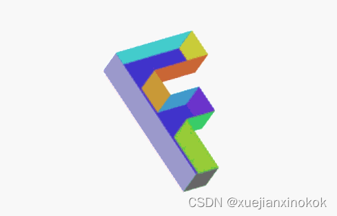
添加深度纹理后,我们现在得到
这才是3D!
正交 (Ortho / Orthographic )
One minor thing. In most 3D math libraries there is no projection function to do our conversions from clip space to pixel space. Rather, there’s usually a function called ortho or orthographic that looks like this
一件小事。在大多数 3D 数学库中,没有 projection 函数来完成从裁剪空间到像素空间的转换。相反,通常有一个名为 ortho 或 orthographic 的函数,看起来像这样
const mat4 = {
  ...
  ortho(left, right, bottom, top, near, far, dst) {
    dst = dst || new Float32Array(16);

    dst[0] = 2 / (right - left);
    dst[1] = 0;
    dst[2] = 0;
    dst[3] = 0;

    dst[4] = 0;
    dst[5] = 2 / (top - bottom);
    dst[6] = 0;
    dst[7] = 0;

    dst[8] = 0;
    dst[9] = 0;
    dst[10] = 1 / (near - far);
    dst[11] = 0;

    dst[12] = (right + left) / (left - right);
    dst[13] = (top + bottom) / (bottom - top);
    dst[14] = near / (near - far);
    dst[15] = 1;

    return dst;
  },
  ...
Unlike our simplified projection function above, which only had width, height, and depth parameters, with this more common orthographic projection function we can pass in left, right, bottom, top, near, and far which gives as more flexibility. To use it the same as our original projection function we’d call it with
与我们上面简化的 projection 函数不同,它只有宽度、高度和深度参数,有了这个更常见的正交投影函数,我们可以传入左、右、下、上、近和远,这提供了更大的灵活性。要像我们原来的投影函数一样使用它,我们会调用它
// mat4.projection(canvas.clientWidth, canvas.clientHeight, 400, matrixValue);
mat4.ortho(
    0,                   // left
    canvas.clientWidth,  // right
    canvas.clientHeight, // bottom
    0,                   // top
    400,                 // near
    -400,                // far
    matrixValue,         // dst
);
接下来我们将讨论如何让它具有透视图。
为什么叫正交投影
在这种情况下,Orthographic 来自正交这个词
orthogonal 正交的
adjective: 形容词:
of or involving right angles
属于或涉及直角
注释1
it’s possible with creative arrangement of the indices we could use @interpolate(flat) as mentioned in the article on inter-stage variables and still use indices.
通过创造性地安排索引,我们可以使用 @interpolate(flat) ,如关于阶段间变量的文章中所述,并且仍然使用索引。


![[Eigen中文文档] 稀疏矩阵操作](https://img-blog.csdnimg.cn/c691a960e075455caab3de3d0fceae45.jpeg#pic_center)