目录
一、前言
二、工程设计
2.1 工程代码
2.2 测试文件代码
2.3 综合结果
2.4 仿真结果
一、前言
分频器即将高频率的信号转化为更低频率的信号,常用的分频可使用锁相环PLL来实现,也可自己编写RTL代码来实现。根据分频的系数N(假设信号频率为M,分频系数为N,则分频后的信号频率为M/N)分为奇数分频和偶数分频,奇数分频根据占空比可分为50%占空比和非50%占空比。
二、工程设计
2.1 工程代码
代码文件中包含了偶数分频,占空比为50%的奇数分频,占空比为非50%的奇数分频。待分频的信号频率为周期1ns的方波信号,偶数分频的分频系数为10,奇数分频的分频系数为7.
奇数分频占空比为50%的实现为一个上升沿触发的奇数分频信号与一个下降沿触发的偶数分频信号相与获得
module Divider(clk,rst,odd_out,even_out,odev_out );
input clk,rst;
output reg odd_out,even_out;
reg clktemp1,clktemp2;
output odev_out;
reg [3:0] counter_o,counter_e,counter_oe1,counter_oe2;
parameter N=10;  //分频系数为10
parameter N1=7;  //分频系数为7
//偶数分频
always@(posedge clk,negedge rst)
begin
if(!rst)
even_out<=0;
else if(counter_e==N/2-1)
begin
even_out<=~even_out;
counter_e<=0;
end
else
counter_e<=counter_e+1;
end

//奇数分频,占空比非50%
always@(posedge clk,negedge rst)
begin
if(!rst)
begin
odd_out<=0;
counter_o<=0;
end
else if(counter_o==(N1-1)/2)
begin
odd_out<=~odd_out;
counter_o<=counter_o+1'b1;
end
else if(counter_o==N1-1)
begin
odd_out<=~odd_out;
counter_o<=0;
end
else
counter_o<=counter_o+1'b1;
end

//奇数分频,占空比为50%
always@(posedge clk,negedge rst)
begin
if(!rst)
begin
clktemp1<=0;
counter_oe1<=0;
end
else if(counter_oe1==(N1-1)/2)
begin
clktemp1<=~clktemp1;
counter_oe1<=counter_oe1+1'b1;
end
else if(counter_oe1==N1-1)
begin
clktemp1<=~clktemp1;
counter_oe1<=0;
end
else
counter_oe1<=counter_oe1+1'b1;
end

always@(negedge clk,negedge rst)
begin
if(!rst)
begin
clktemp2<=0;
counter_oe2<=0;
end
else if(counter_oe2==(N1-1)/2)
begin
clktemp2<=~clktemp2;
counter_oe2<=counter_oe2+1'b1;
end
else if(counter_oe2==N1-1)
begin
clktemp2<=~clktemp2;
counter_oe2<=0;
end
else
counter_oe2<=counter_oe2+1'b1;
end
assign odev_out=clktemp1|clktemp2;
endmodule
2.2 测试文件代码
`timescale 1ns / 1ps
module Divider_tb( );
reg clk,rst;
wire odd_out,even_out,odev_out;
initial
begin
clk=0;
rst=1;
#100 rst=0;
#50 rst=1;
#1000 $stop;   //仿真到1000ns时停止仿真
end
always #1 clk=~clk;  //clk信号周期为2ns
Divider divider_test(.clk(clk),.rst(rst),.odd_out(odd_out),.even_out(even_out),.odev_out(odev_out));
endmodule
2.3 综合结果
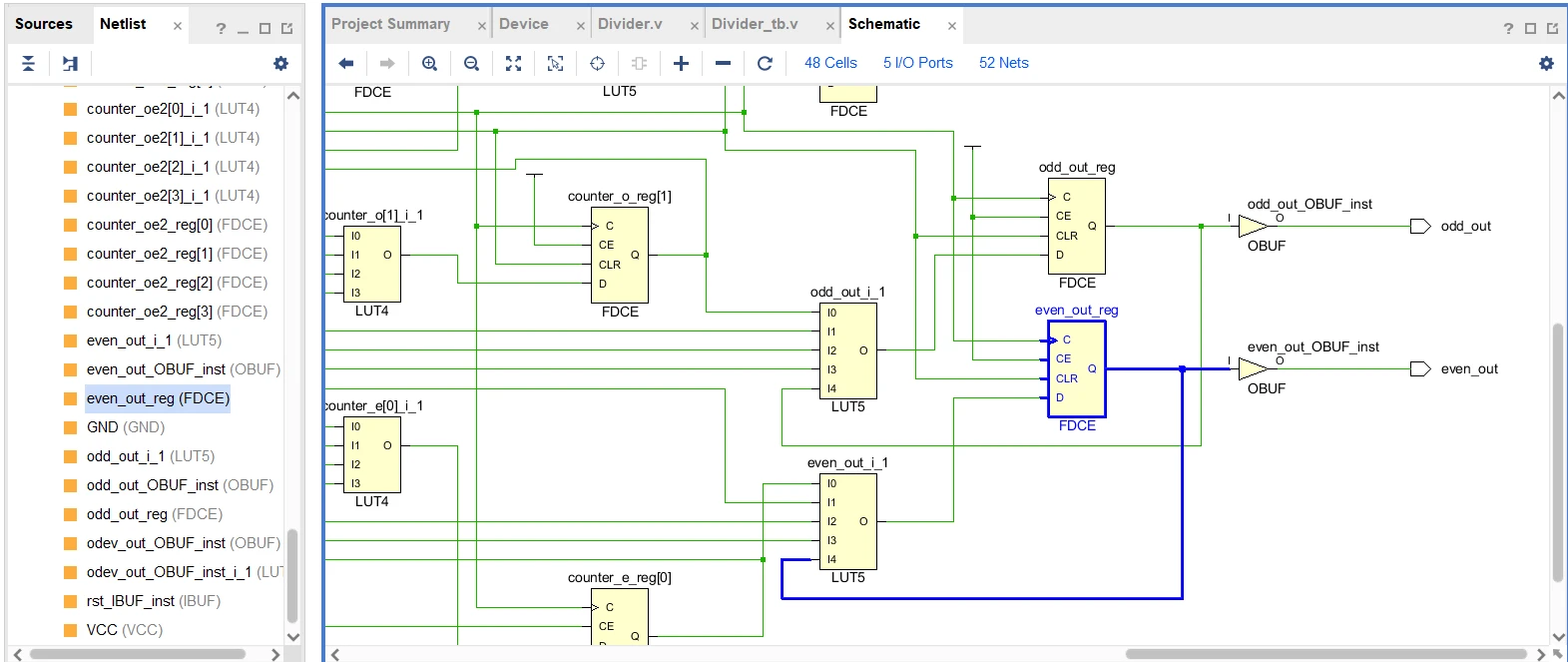
途中odev_out为占空比50%的奇数分频输出,由综合结果可知采用了一个LUT2来实现clktemp1和clktemp2的相与操作,clktemp1和clktemp2即为相同奇数分频的信号,区别是一个一个上升沿触发,一个下降沿触发
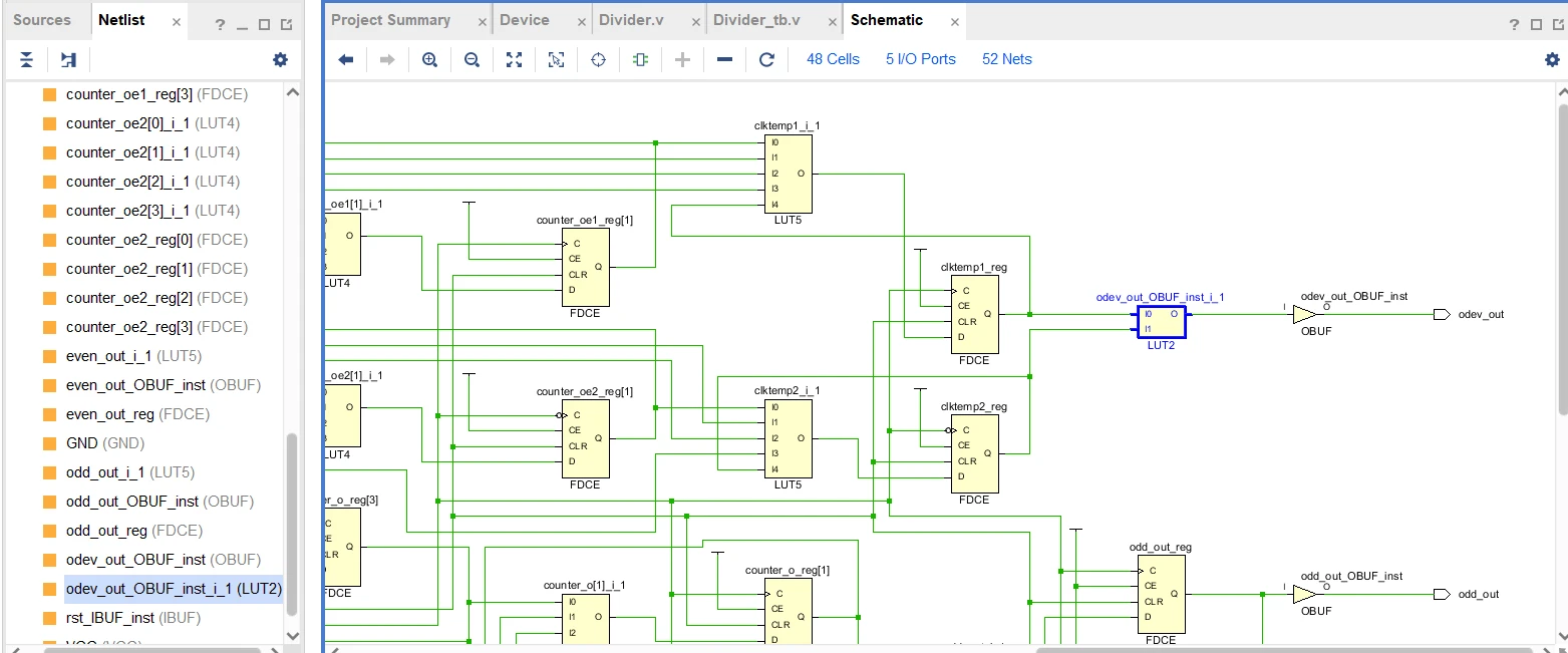
信号反向的操作,以信号even_out输出为例,即将FDCE的输出Q反馈连接到LUT5的输入,再传输到FDCE的数据输入端口D。
2.4 仿真结果
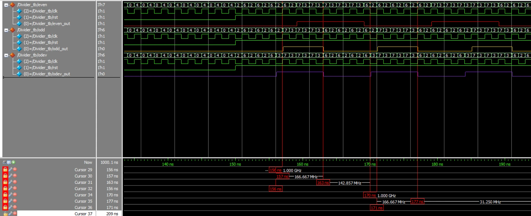
图中红色为偶数分频的输出,周期为20ns,黄色为基数分频信号,占空比非50%,紫色为基数分频信号,占空比为50%
