一般商用的rgbd相机的sdk自带d2c的api,但是LZ还是想利用空闲时间理解下其原理。
第一步:标定彩色相机和深度相机。
分别采集若干张彩色摄像头和红外摄像头(对于带有红外摄像头进行深度测量的深度摄像头,红外摄像头和深度摄像头其实是同一个)的标定板成像图片。LZ这里各采集了9张,如下所示:


这里除了第一组图片(color.bmp和ir.bmp)需要在同一场景下拍摄,其他的color图片和ir图片不需要一一对应,可以分开采集。注意,红外摄像头直接拍摄标定板可能成像不清楚,会存在大量噪声影响标定板角点提取。此时可以遮挡住红外发射器,并使用红外光源照射标定板(参考深度图与彩色图的配准与对齐)。
标定程序:
#include <iostream>
#include <fstream>
#include <opencv2/opencv.hpp>

#define BOARD_SCALE 30//棋盘格边长(mm)
#define BOARD_HEIGHT 5//棋盘格高度方向角点个数
#define BOARD_WIDTH 8 //棋盘格宽度方向角点个数

/**
 * @brief CamraCalibration  相机标定
 * @param files             文件名
 * @param cameraMatrix      内参矩阵
 * @param distCoeffs        畸变系数
 * @param tvecsMat          平移矩阵
 * @param rvecsMat          旋转矩阵
 */
void CamraCalibration(std::vector<std::string>& files, cv::Mat& cameraMatrix, cv::Mat& distCoeffs,
	std::vector<cv::Mat>& tvecsMat, std::vector<cv::Mat>& rvecsMat)
{
	//读取每一幅图像,从中提取出角点,然后对角点进行亚像素精确化
	int image_count = 0;  /* 图像数量 */
	cv::Size image_size;  /* 图像的尺寸 */
	cv::Size board_size = cv::Size(BOARD_HEIGHT, BOARD_WIDTH);    /* 标定板上每行、列的角点数 */
	std::vector<cv::Point2f> image_points_buf;  /* 缓存每幅图像上检测到的角点 */
	std::vector<std::vector<cv::Point2f>> image_points_seq; /* 保存检测到的所有角点 */

	for (int i = 0; i < files.size(); i++)
	{
		std::cout << files[i] << std::endl;
		cv::Mat imageInput = cv::imread(files[i]);

		/* 提取角点 */
		if (0 == findChessboardCorners(imageInput, board_size, image_points_buf))
		{
			std::cout << "can not find chessboard corners!\n"; //找不到角点
			continue;
		}
		else
		{
			//找到一幅有效的图片
			image_count++;
			if (image_count == 1)  //读入第一张图片时获取图像宽高信息
			{
				image_size.width = imageInput.cols;
				image_size.height = imageInput.rows;
			}

			cv::Mat view_gray;
			cvtColor(imageInput, view_gray, cv::COLOR_RGB2GRAY);

			/* 亚像素精确化 */
			cornerSubPix(view_gray, image_points_buf, cv::Size(5, 5), cv::Size(-1, -1),
				cv::TermCriteria(cv::TermCriteria::MAX_ITER + cv::TermCriteria::EPS, 30, 0.1));

			image_points_seq.push_back(image_points_buf);  //保存亚像素角点
		}
	}

	int total = image_points_seq.size();
	std::cout << "共使用了" << total << "幅图片" << std::endl;
	std::cout << "角点提取完成!\n";

	/*棋盘三维信息*/
	cv::Size square_size = cv::Size(BOARD_SCALE, BOARD_SCALE);  /* 实际测量得到的标定板上每个棋盘格的大小 */
	std::vector<std::vector<cv::Point3f>> object_points; /* 保存标定板上角点的三维坐标 */
	cameraMatrix = cv::Mat(3, 3, CV_32FC1, cv::Scalar::all(0)); /* 摄像机内参数矩阵 */
	std::vector<int> point_counts;  // 每幅图像中角点的数量
	distCoeffs = cv::Mat(1, 4, CV_32FC1, cv::Scalar::all(0)); /* 摄像机的畸变系数:k1,k2,p1,p2 */

	/* 初始化标定板上角点的三维坐标 */
	int i, j, t;
	for (t = 0; t < image_count; t++)
	{
		std::vector<cv::Point3f> tempPointSet;
		for (i = 0; i < board_size.height; i++)
		{
			for (j = 0; j < board_size.width; j++)
			{
				cv::Point3f realPoint;
				/* 假设标定板放在世界坐标系中z=0的平面上 */
				realPoint.x = i * square_size.width;
				realPoint.y = j * square_size.height;
				realPoint.z = 0;
				tempPointSet.push_back(realPoint);
			}
		}
		object_points.push_back(tempPointSet);
	}

	/* 初始化每幅图像中的角点数量,假定每幅图像中都可以看到完整的标定板 */
	for (i = 0; i < image_count; i++)
	{
		point_counts.push_back(board_size.width * board_size.height);
	}

	/* 开始标定 */
	cv::calibrateCamera(object_points, image_points_seq, image_size, cameraMatrix, distCoeffs, rvecsMat, tvecsMat, cv::CALIB_FIX_K3);
	std::cout << "标定完成!\n" << std::endl;

	//对标定结果进行评价
	std::ofstream fout("calibration_result.txt");  /* 保存标定结果的文件 */
	double total_err = 0.0; /* 所有图像的平均误差的总和 */
	double err = 0.0; /* 每幅图像的平均误差 */
	std::vector<cv::Point2f> image_points2; /* 保存重新计算得到的投影点 */
	std::cout << "每幅图像的标定误差:\n";
	fout << "每幅图像的标定误差:\n";
	for (i = 0; i < image_count; i++)
	{
		std::vector<cv::Point3f> tempPointSet = object_points[i];
		/* 通过得到的摄像机内外参数,对空间的三维点进行重新投影计算,得到新的投影点 */
		projectPoints(tempPointSet, rvecsMat[i], tvecsMat[i], cameraMatrix, distCoeffs, image_points2);
		/* 计算新的投影点和旧的投影点之间的误差*/
		std::vector<cv::Point2f> tempImagePoint = image_points_seq[i];
		cv::Mat tempImagePointMat = cv::Mat(1, tempImagePoint.size(), CV_32FC2);
		cv::Mat image_points2Mat = cv::Mat(1, image_points2.size(), CV_32FC2);
		for (int j = 0; j < tempImagePoint.size(); j++)
		{
			image_points2Mat.at<cv::Vec2f>(0, j) = cv::Vec2f(image_points2[j].x, image_points2[j].y);
			tempImagePointMat.at<cv::Vec2f>(0, j) = cv::Vec2f(tempImagePoint[j].x, tempImagePoint[j].y);
		}
		err = norm(image_points2Mat, tempImagePointMat, cv::NORM_L2);
		total_err += err /= point_counts[i];
		std::cout << "第" << i + 1 << "幅图像的平均误差:" << err << "像素" << std::endl;
		fout << "第" << i + 1 << "幅图像的平均误差:" << err << "像素" << std::endl;
	}

	std::cout << "总体平均误差:" << total_err / image_count << "像素\n" << std::endl;
	fout << "总体平均误差:" << total_err / image_count << "像素" << std::endl << std::endl;

	//保存定标结果
	cv::Mat rotation_matrix = cv::Mat(3, 3, CV_32FC1, cv::Scalar::all(0)); /* 保存每幅图像的旋转矩阵 */
	std::cout << "相机内参数矩阵:" << std::endl;
	std::cout << cameraMatrix << std::endl << std::endl;
	std::cout << "畸变系数:" << std::endl;
	std::cout << distCoeffs << std::endl << std::endl;
	fout << "相机内参数矩阵:" << std::endl;
	fout << cameraMatrix << std::endl << std::endl;
	fout << "畸变系数:" << std::endl;
	fout << distCoeffs << std::endl << std::endl;
	for (int i = 0; i < image_count; i++)
	{
		fout << "第" << i + 1 << "幅图像的平移向量:" << std::endl;
		fout << tvecsMat[i].t() << std::endl;
		/* 将旋转向量转换为相对应的旋转矩阵 */
		Rodrigues(rvecsMat[i], rotation_matrix);
		fout << "第" << i + 1 << "幅图像的旋转矩阵:" << std::endl;
		fout << rotation_matrix << std::endl << std::endl;
	}
	fout << std::endl;
}

int main(int argc, char* argv[])
{
	std::vector<std::string> files;
	std::vector<cv::Mat> tvecsMat, rvecsMat;
	cv::Mat cameraMatrix, distCoeffs;
	cv::glob("./images", files, true);
	CamraCalibration(files, cameraMatrix, distCoeffs, tvecsMat, rvecsMat);
	return EXIT_SUCCESS;
}
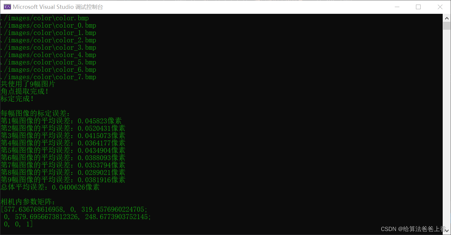
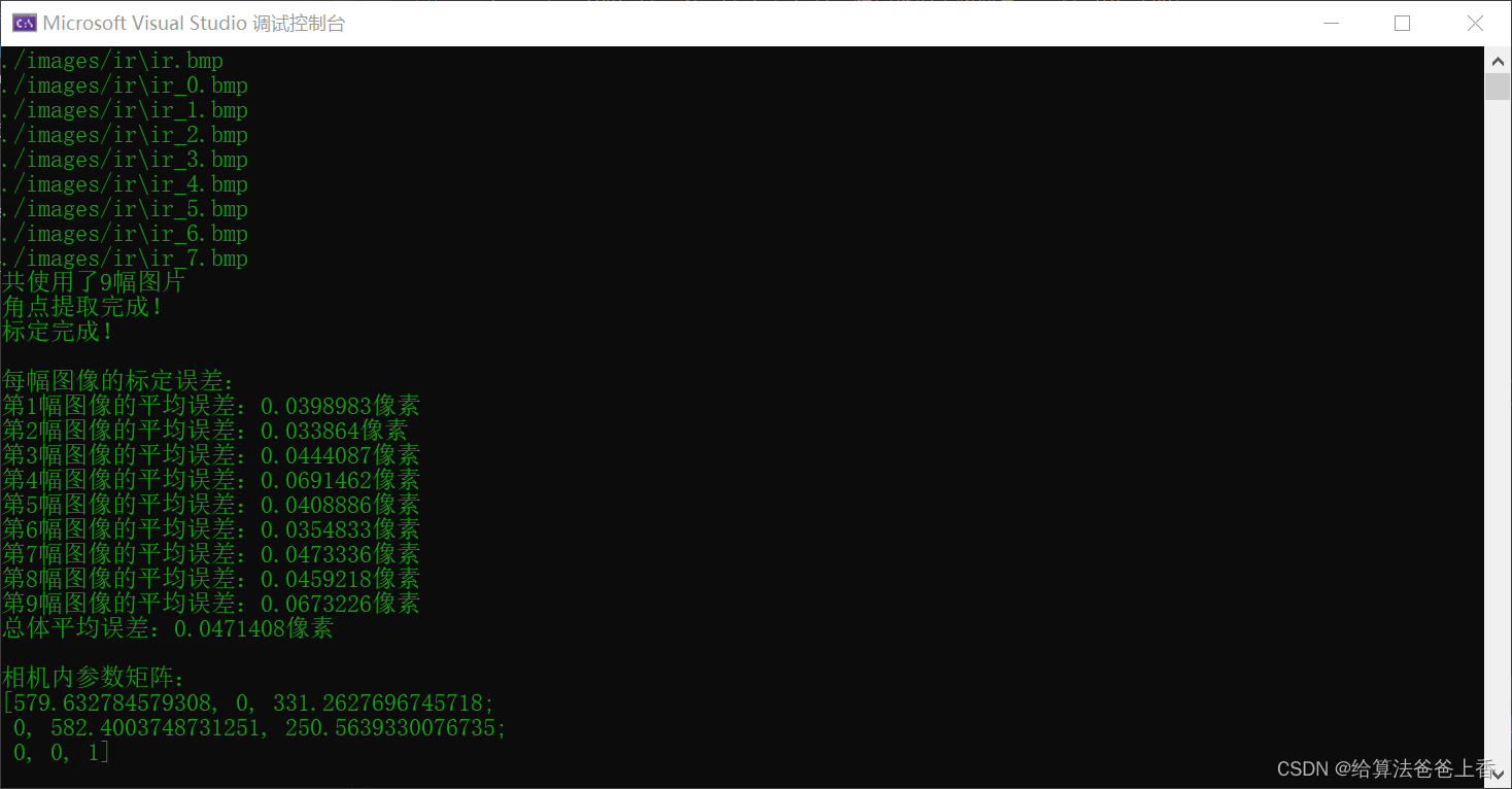
根据自己标定板参数设置BOARD_SCALE、BOARD_HEIGHT和BOARD_WIDTH的值。标定彩色相机和红外相机的内参如下:
第二步:求解深度相机到彩色相机的变换矩阵
第一步中的程序计算出color.bmp和ir.bmp这两张图片对应的相机外参分别为:


求解深度相机到彩色相机的变换矩阵的原理:(参考深度图与彩色图的配准与对齐,其实就是求解一个4*4刚性变换矩阵)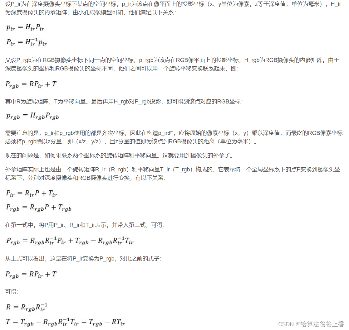
使用下面程序计算深度相机到彩色相机的变换矩阵:
#include <iostream>
#include <Eigen/Dense>

int main()
{
	Eigen::Matrix3f Rir, Rrgb, R;
	Rir << 0.9388621034681646, 0.04409712279151825, 0.341457749118165,
	0.01647972263398413, -0.9963828535584762, 0.0833644281247999,
	0.3438987778594756, -0.07264057334697833, -0.9361928101040838;
	Rrgb << 0.9430537754163527, 0.04244549558711521, 0.3299211369059707,
	0.01733461460525522, -0.9967487635113179, 0.0786855359970694,
	0.332188331838208, -0.06848563603430294, -0.940723460878661;

	Eigen::Vector3f Tir, Trgb, T;
	Tir << -167.0131975581419, -2.579261897319864, 405.3398579424809;
	Trgb << -124.6158422573672, 4.649293541474578, 407.7379454786609;

	Eigen::Matrix4f trans_ir, trans_rgb, trans;
	trans_ir << Rir, Tir, 0, 0, 0, 1;
	trans_rgb << Rrgb, Trgb, 0, 0, 0, 1;

	R = Rrgb * Rir.inverse();
	T = Trgb - R * Tir;
	std::cout << " R=\n" << R << std::endl << "T=\n" << T << std::endl;

	trans = trans_rgb * trans_ir.inverse();
	std::cout << "transformation matrix=\n" << trans << std::endl;

	return 0;
}
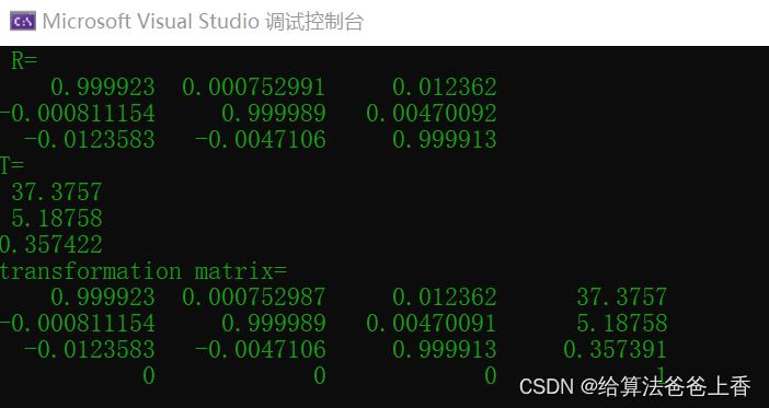
求解结果如下:
第三步:rgbd对齐(配准)
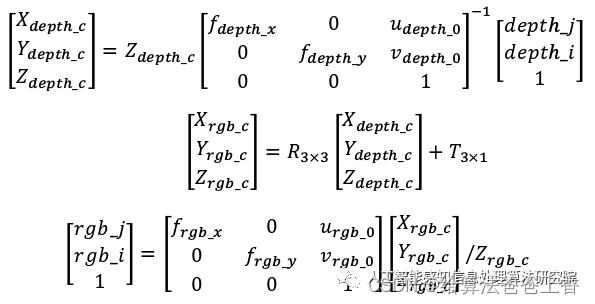
原理参考:RGB 图像与深度图像对齐
将第一步、第二步标定得到的彩色相机和深度相机的内参以及深度相机到彩色相机的变换矩阵填入下面程序的对应位置:
#include <iostream>
#include <fstream>
#include <opencv2/opencv.hpp>
#include <pcl/io/pcd_io.h>
#include <pcl/point_types.h>

// 相机内参
double color_cx = 319.4576960224705;
double color_cy = 248.6773903752145;
double color_fx = 577.636768616958;
double color_fy = 579.6956673812326;

double depth_cx = 331.2627696745718;
double depth_cy = 250.5639330076735;
double depth_fx = 579.632784579308;
double depth_fy = 582.4003748731251;

int main(int argc, char* argv[])
{
	cv::Mat color = cv::imread("color_1.png", 1);
	cv::Mat depth = cv::imread("depth_1.png", -1);

	pcl::PointCloud<pcl::PointXYZRGB>::Ptr cloud(new pcl::PointCloud<pcl::PointXYZRGB>);
	std::ofstream outfile("cloud_1.txt");

	int point_nums = 0;
	for (int i = 0; i < depth.rows; ++i)
	{
		for (int j = 0; j < depth.cols; ++j)
		{
			short d = depth.ptr<short>(i)[j];

			if (d == 0)
				continue;

			point_nums++;

			pcl::PointXYZRGB p;
			p.z = double(d);
			p.x = (j - depth_cx) * p.z / depth_fx;
			p.y = (i - depth_cy) * p.z / depth_fy;

			Eigen::Matrix3f R; //d2c旋转矩阵
			R << 0.999923, 0.000752991, 0.012362,
				-0.000811154, 0.999989, 0.00470092,
				-0.0123583, -0.0047106, 0.999913;
			Eigen::Vector3f T(37.3757, 5.18758, 0.357422); //d2c平移向量

			Eigen::Vector3f Pd = p.getArray3fMap();
			Eigen::Vector3f Pc = R * Pd + T;

			int n = Pc.x() * color_fx / Pc.z() + color_cx;
			if (n < 0)n = 0;
			if (n >= color.cols)n = color.cols - 1;

			int m = Pc.y() * color_fy / Pc.z() + color_cy;
			if (m < 0)m = 0;
			if (m >= color.rows)m = color.rows - 1;

			p.b = color.at<cv::Vec3b>(m, n)[0];
			p.g = color.at<cv::Vec3b>(m, n)[1];
			p.r = color.at<cv::Vec3b>(m, n)[2];

			cloud->points.push_back(p);
			outfile << p.x << " " << p.y << " " << p.z << " " << (int)p.r << " " << (int)p.g << " " << (int)p.b << std::endl;
		}
	}

	cloud->width = point_nums;
	cloud->height = 1;
	//pcl::io::savePCDFile("cloud_1.pcd", *cloud);
	outfile.close();

	return 0;
}
rgbd对齐前后点云可视化结果:
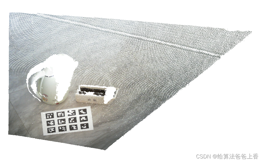
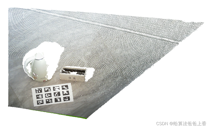
注意包装盒的右侧、水壶的把手以及右侧和地面接近部分的点云在rgbd对齐前后可以看出较大区别。



![[自学记录03|百人计划]移动端GPU的TB(D)R架构基础](https://img-blog.csdnimg.cn/b69a57c5a73f41279a66fa42027b7026.png)
