目录
一、为什么要使用生成树(STP):
二、由于设备冗余而导致的问题:
广播风暴:
三、802.1D生成树基本配置
四、802.1D生成树实验
实验拓扑:
实验配置:
配置完成后,在SW8上观察现象:
从中我们可以总结:
拓展知识:
实验思路:
一、修改RID
二、修改RPC达到选取根端口的目的(RPC即路径开销,修改时需要在交换机入接口进行修改)
三、修改BID:
四、修改PID:
配置:
五、RSTP
为什么要使用RSTP?
本次实验使用两个拓扑来解释RSTP:
一、利用简单的拓扑解释RSTP:
实验配置:
六、利用802.1D生成树中的拓扑来实现MSTP的功能:
实验配置:
六、MSTP
使用原因:
配置完成后,在SW3上查看实例1和实例2的生成树表:
一、为什么要使用生成树(STP):
- 以太网交换网络中为了进行链路备份,提高网络可靠性,通常会使用冗余链路。但是使用冗余链路会 在交换网络上产生环路,引发广播风暴以及MAC地址表不稳定等故障现象,从而导致用户通信质量较 差,甚至通信中断。为解决交换网络中的环路问题,提出了生成树协议STP(Spanning Tree)。
-
随着局域网规模的不断扩大,越来越多的交换机被用来实现主机之间的互连。如图,接入层交换机 单链路上联,则存在单链路故障,也就是如果这根上联链路发生故障,交换机下联用户就断网了。 另一个问题的单点故障,也就是交换机如果宕机,交换机下联用户也就断网了。
-
为了解决此类问题,交换机在互连时一般都会使用冗余链路来实现备份。冗余链路虽然增强了网络 的可靠性,但是也会产生环路,而环路会带来一系列的问题,继而导致通信质量下降和通信业务中 断等问题。
二、由于设备冗余而导致的问题:
广播风暴:
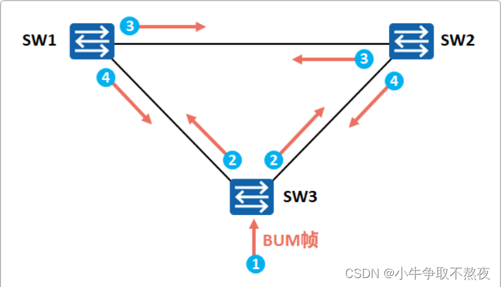
由于物理之间的备份,在SW3收到来自外界的信号后,会进行洪范,向SW1和SW2进行洪范,且因为交换机中没有类似于TTL值的参数,会导致该广播包一直在交换机中洪范,形成广播风暴及mac地址飘逸。最终结果使整个网络资源被消耗殆尽,网络瘫痪不可用。
三、802.1D生成树基本配置
1. 配置生成树工作模式
[Huawei] stp mode { stp | rstp | mstp }
交换机支持STP、RSTP和MSTP(Multiple Spanning Tree Protocol)三种生成树工作模式,默认情况工
作在MSTP模式。

2. (可选)配置根桥
[Huawei] stp root primary
配置当前设备为根桥。缺省情况下,交换机不作为任何生成树的根桥。配置后该设备优先级数值自动为
0,并且不能更改设备优先级

3. (可选)备份根桥
[Huawei] stp root secondary
配置当前交换机为备份根桥。缺省情况下,交换机不作为任何生成树的备份根桥。配置后该设备优先级
数值为4096,并且不能更改设备优先级。

4. (可选)配置交换机的STP优先级
[Huawei] stp priority priority
缺省情况下,交换机的优先级取值是32768。

5. (可选)配置接口路径开销
[Huawei] stp pathcost**-standard** { dot1d-1998 | dot1t | legacy }
配置接口路径开销计算方法。缺省情况下,路径开销值的计算方法为IEEE 802.1t(dot1t)标准方法。
同一网络内所有交换机的接口路径开销应使用相同的计算方法。
[Huawei-GigabitEthernet0/0/1] stp cost cost
设置当前接口的路径开销值。

6. (可选)配置接口优先级
[Huawei-intf] stp priority priority
配置接口的优先级。缺省情况下,交换机接口的优先级取值是128。

7. 启用STP/RSTP/MSTP
[Huawei] stp enable
使能交换机的STP/RSTP/MSTP功能。缺省情况下,设备的STP/RSTP/MSTP功能处于启用状态。
RSTP
interface g0/0/1
undo stp enable //接口下关闭生成树,此接口不参与生成树构建
port-group group-member g0/0/1 to g0/0/4 //接口组配置,可以把相同配置的接口一次性配置
完毕
四、802.1D生成树实验
实验拓扑:
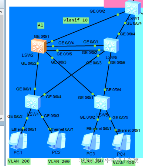
我们选取SVI的实验来进行总结生成树中的知识:
其中LSW2和LS8是汇聚层的交换机,两者之间互相连线实现设备和线路冗余,而LSW4和LS5则s是接入层交换机,实现终端的接入。
实验配置:
SW2:
#
sysname sw2
#
vlan batch 10 200 300 400                    #创建vlan
#
stp mode stp                                 #生成树模式变更为stp
stp instance 0 root primary                  #配置当前设备为根桥。配置后该设备优先级数值自动
                                              为0,并且不能更改设备优先级。

#
interface Vlanif10
 ip address 192.168.0.1 255.255.255.252
 ospf network-type p2p
#
interface Vlanif200
 ip address 192.168.20.1 255.255.255.0
 dhcp select interface
#
interface Vlanif300
 ip address 192.168.30.1 255.255.255.0
 dhcp select interface
#
interface Vlanif400
 ip address 192.168.40.1 255.255.255.0
 dhcp select interface
#
interface MEth0/0/1
#
interface GigabitEthernet0/0/1
 port link-type trunk
 undo port trunk allow-pass vlan 1
 port trunk allow-pass vlan 10
 stp disable
#
interface GigabitEthernet0/0/2
 port link-type trunk
 undo port trunk allow-pass vlan 1
 port trunk allow-pass vlan 200
#
interface GigabitEthernet0/0/3
 port link-type trunk
 undo port trunk allow-pass vlan 1
 port trunk allow-pass vlan 300 400
#
interface GigabitEthernet0/0/4
 port link-type trunk
 undo port trunk allow-pass vlan 1
 port trunk allow-pass vlan 200 300 400
#
interface GigabitEthernet0/0/5
 port link-type trunk
 undo port trunk allow-pass vlan 1
 port trunk allow-pass vlan 200 300 400
 stp instance 0 port priority 0
SW8:
#
sysname sw8
#
stp mode stp
stp instance 0 root secondary                    # 配置当前交换机为备份根桥。

#
interface GigabitEthernet0/0/1
 port link-type trunk
 undo port trunk allow-pass vlan 1
 port trunk allow-pass vlan 200 300 400
 stp instance 0 cost 1
#
interface GigabitEthernet0/0/2
 port link-type trunk
 undo port trunk allow-pass vlan 1
 port trunk allow-pass vlan 200 300 400
 stp instance 0 cost 1
#
interface GigabitEthernet0/0/3
 port link-type trunk
 undo port trunk allow-pass vlan 1
 port trunk allow-pass vlan 200
#
interface GigabitEthernet0/0/4
 port link-type trunk
 undo port trunk allow-pass vlan 1
 stp disable
#
interface GigabitEthernet0/0/5
 port link-type trunk
 undo port trunk allow-pass vlan 1
 port trunk allow-pass vlan 300 400
SW4:
sysname sw4
#
vlan batch 200
#
stp mode stp
#
cluster enable
ntdp enable
ndp enable
#
drop illegal-mac alarm
#
diffserv domain default
#
drop-profile default
#
aaa
 authentication-scheme default
 authorization-scheme default
 accounting-scheme default
 domain default
 domain default_admin
 local-user admin password simple admin
 local-user admin service-type http
#
interface Vlanif1
#
interface MEth0/0/1
#
interface GigabitEthernet0/0/1
 port link-type trunk
 undo port trunk allow-pass vlan 1
 port trunk allow-pass vlan 200
#
interface GigabitEthernet0/0/2
 port link-type access
 port default vlan 200
#
interface GigabitEthernet0/0/3
 port link-type access
 port default vlan 200
#
interface GigabitEthernet0/0/4
 port link-type trunk
 undo port trunk allow-pass vlan 1
 port trunk allow-pass vlan 200
SW5:
#
sysname sw5
#
vlan batch 300 400
#
stp mode stp
#
cluster enable
ntdp enable
ndp enable
#
drop illegal-mac alarm
#
diffserv domain default
#
drop-profile default
#
aaa
 authentication-scheme default
 authorization-scheme default
 accounting-scheme default
 domain default
 domain default_admin
 local-user admin password simple admin
 local-user admin service-type http
#
interface Vlanif1
#
interface MEth0/0/1
#
interface GigabitEthernet0/0/1
 port link-type trunk
 undo port trunk allow-pass vlan 1
 port trunk allow-pass vlan 300 400
#
interface GigabitEthernet0/0/2
 port link-type access
 port default vlan 300
#
interface GigabitEthernet0/0/3
 port link-type access
 port default vlan 400
#
interface GigabitEthernet0/0/4
 port link-type trunk
 undo port trunk allow-pass vlan 1
 port trunk allow-pass vlan 300 400
#
配置完成后,在SW8上观察现象:

- 由于实验设置SW2交换机是根网桥,所以只有SW2在配置完成后发送BPDU,其他交换机在之后只进行选取根端口。
- 从图中我们可以发现G0/0/1是根接口。而G0/0/2则是阻塞端口,DISCARDING代表阻塞状态。
从中我们可以总结:
- DESI则代表指定端口,结束后状态归为转发状态(从一开始down到listening到learning到forwarding)
- listening状态代表已经选取完根网桥,当接口处于该状态时,STP初步认定该接口为根接口或指定接口,但接口依然处于STP计算的过程中,此时接口可以收发BPDU,但是不能收发业务数据帧,也不会进行MAC地址学习。
- leaning状态代表当接口处于该状态时,会侦听业务数据帧(但是不能转发业务数据帧),并且在收到业务数据帧后进行MAC地址学习。
-
forwarding状态代表处于该状态的接口可以正常地收发业务数据帧,也会进行BPDU处理。接口的 角色需是根接口或指定接口才能进入转发状态。
拓展知识:
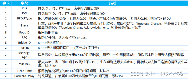
实验思路:
一、修改RID
由于Root ID 均为SW2,所以修改SW2无法到达选取根接口的目的。(Root ID是由优先级+MAC地址得到)
二、修改RPC达到选取根端口的目的(RPC即路径开销,修改时需要在交换机入接口进行修改)
我们先在g0/0/1的接口查看stp的具体参数,不难发现一开始RPC值为20000,所以我们进行修改。所以我们可以修改RPC值为1,越小越优,从而导致根接口为g/0/0/2。

实验配置:
interface GigabitEthernet0/0/2
stp instance 0 cost 1
查询根接口:

三、修改BID:
由于BID(桥ID)也是MAC地址+优先级计算出值,但因为SW8到达SW2的路径是一样的,故MAC地址是一样的,所以修改优先级无法达成实验效果,故通过BID无法到达选取效果。
四、修改PID:
由于PID(Port ID)是接口号+优先级计算出值,由于接口号不同,所以只需修改优先级便可完成实验需求。

从LW8上截图我们可以发现优先级是128(或128的倍数),只需要在LSW2上修改优先级即可达成实验要求。(优先级在根网桥上进行,RPC在根端口上进行)
配置:
SW2:
stp instance 0 port priority 0
从SW8上查看根接口:

此时,G0/0/2为根接口。
五、RSTP
为什么要使用RSTP?
解释:
- STP协议虽然能够解决环路问题,但是由于网络拓扑收敛慢,影响了用户通信质量。如果网络中的 拓扑结构频繁变化,网络也会随之频繁失去连通性,从而导致用户通信频繁中断,这是用户无法忍 受的。
- STP没有细致区分接口状态和接口角色,不利于初学者学习及部署。
- 网络协议的优劣往往取决于协议是否对各种情况加以细致区分。
- 从用户角度来讲,Listening、Learning和Blocking状态并没有区别,都同样不转发用户流 量。 从使用和配置角度来讲,接口之间最本质的区别并不在于接口状态,而是在于接口扮演的角 色。
- 根接口和指定接口可以都处于Listening状态,也可能都处于Forwarding状态。
- STP算法是被动的算法,依赖定时器等待的方式判断拓扑变化,收敛速度慢。
- STP算法要求在稳定的拓扑中,根桥主动发出配置BPDU报文,而其他设备进行处理,传遍整个STP 网络。这也是导致拓扑收敛
本次实验使用两个拓扑来解释RSTP:
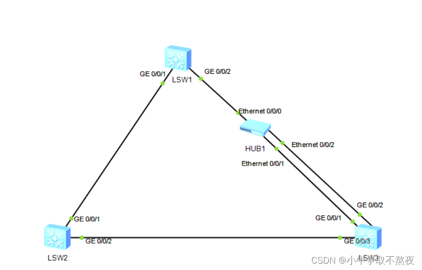
一、利用简单的拓扑解释RSTP:
实验拓扑:
实验配置:
SW1(其余两台设备配置与其相同):
stp mode rstpSW2:
stp instance 0 root primary #设置其优先级为0.默认该设备为根桥。SW3:
stp instance 0 root secondary #设置优先级为4096,默认为根桥的备份此时,我们查看SW1,SW2,SW3上的生成树:
SW1:

一个接口角色为ALTE,代表他是根接口的备份。状态时DISCARDING(即不转发数据也不学习mac地址,在802.1D生成树中,disabled,blocking,listening都与其一样)
SW3:

一个接口角色为ALTE,代表他是根接口的备份。而一个接口为BACK,此为desigenation(即指定端口)的备份,这是因为SW3为根网桥备份,所以G0/0/2的接口此时为角色。而其余接口状态均为forwarding(即转发)。
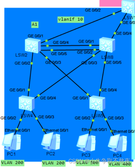
六、利用802.1D生成树中的拓扑来实现MSTP的功能:
实验拓扑:
实验配置:
SW8:
<sw8>
#
stp mode rstp                                   #修改生成树类型为rstp
stp instance 0 root secondary
#
 stp root-protection
#
interface GigabitEthernet0/0/5
 stp root-protection                            #根保护,目的是防止外来接入设备而导致的生成
                                                 树动荡

#interface GigabitEthernet0/0/2
 stp tc-protection
#tc保护,tc本身是生成树创造出来为了应付拓扑变更而设置的,即tcn。而如果被恶意用户侵占,伪造大量TC置位的RST BPDU并向外发送。SW2收到这些RST BPDU后,会频繁执行MAC地址表项的删 除操作形成巨大负担。(从某个接口收到tc消息,将会删除该接口的mac地址)。
SW4:
<sw4>
#
stp mode rstp                            #修改生成树类型rstp
stp bpdu-protection                      #开启bpdu保护,是防止边缘端口中有恶意攻击交换设备,交
                                          换设备会自动将边缘端口设置为非边缘端口,并重新进行生
                                          成树计算,从而引起网络震荡。
#
interface GigabitEthernet0/0/2
 stp edged-port enable                   #开启边缘端口,让下游的终端接口不参与生成树计算。

#
interface GigabitEthernet0/0/4
 stp loop-protection                     #开启环路保护,主要目的是为了防止光纤的的单向链路故障
                                          或链路堵塞而导致的成环问题。
六、MSTP
使用原因:
STP在STP基础上进行了改进,实现了网络拓扑快速收敛。但在划分VLAN的网络中RSTP/STP,局域网内所有的VLAN共享一棵生成树,被阻塞后的链路将不承载任何流量,无法在 VLAN间实现数据流量的负载均衡,导致链路带宽利用率、设备资源利用率较低。故诞生了MSTP。
实验拓扑:
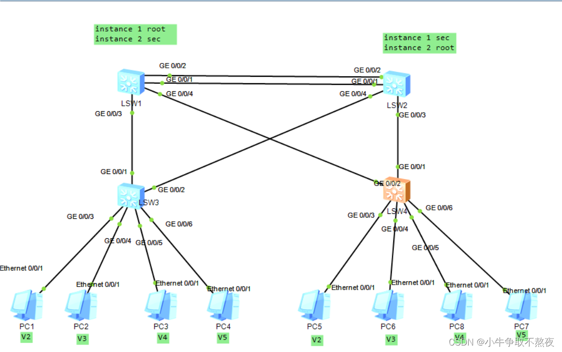
SW1:
#
vlan batch 2 to 5                             #创建VLAN

#
stp instance 1 root primary                   #将此交换机设置为实例1的主根
stp instance 2 root secondary                 #将此交换机设置为实例2的备份根
#
stp region-configuration                      #进入MSTP域视图
 region-name nnn                              #每个域中的MSTP名字应一样
 instance 1 vlan 2 to 3                       #将vlan2 3 划分到 实例1 中 域中每个路由器配置
                                               相同
 instance 2 vlan 4 to 5
 active region-configuration                  #启动MSTP域
#
interface GigabitEthernet0/0/1
 port link-type trunk
 undo port trunk allow-pass vlan 1
 port trunk allow-pass vlan 2 to 4
#
interface GigabitEthernet0/0/2
 port link-type trunk
 undo port trunk allow-pass vlan 1
 port trunk allow-pass vlan 2 to 4
#
interface GigabitEthernet0/0/3
 port link-type trunk
 undo port trunk allow-pass vlan 1
 port trunk allow-pass vlan 2 to 5
 stp root-protection
#
interface GigabitEthernet0/0/4
 port link-type trunk
 undo port trunk allow-pass vlan 1
 port trunk allow-pass vlan 2 to 5
 stp root-protection                        #根保护
SW2:
#
vlan batch 2 to 5
#
stp instance 1 root secondary                #与SW1配置相同
stp instance 2 root primary
#
stp region-configuration                     #整个域配置相同
 region-name nnn
 instance 1 vlan 2 to 3
 instance 2 vlan 4 to 5
 active region-configuration
#
interface GigabitEthernet0/0/1
 port link-type trunk
 undo port trunk allow-pass vlan 1
 port trunk allow-pass vlan 2 to 5
#
interface GigabitEthernet0/0/2
 port link-type trunk
 undo port trunk allow-pass vlan 1
 port trunk allow-pass vlan 2 to 5
#
interface GigabitEthernet0/0/3
 port link-type trunk
 undo port trunk allow-pass vlan 1
 port trunk allow-pass vlan 2 to 5
 stp root-protection
#
interface GigabitEthernet0/0/4
 port link-type trunk
 undo port trunk allow-pass vlan 1
 port trunk allow-pass vlan 2 to 5
 stp root-protection
SW3:
#
vlan batch 2 to 5
#
stp bpdu-protection                            #设置BPDU保护,防止边缘端口出问题
#
stp region-configuration
 region-name nnn
 instance 1 vlan 2 to 3
 instance 2 vlan 4 to 5
 active region-configuration
#
interface GigabitEthernet0/0/1
 port link-type trunk
 undo port trunk allow-pass vlan 1
 port trunk allow-pass vlan 2 to 5
 stp loop-protection                           #设置环路保护
#
interface GigabitEthernet0/0/2
 port link-type trunk
 undo port trunk allow-pass vlan 1
 port trunk allow-pass vlan 2 to 5
#
interface GigabitEthernet0/0/3
 port link-type access
 port default vlan 2
 stp edged-port enable                         #设置边缘端口
#
interface GigabitEthernet0/0/4
 port link-type access
 port default vlan 3
 stp edged-port enable
#
interface GigabitEthernet0/0/5
 port link-type access
 port default vlan 4
 stp edged-port enable
#
interface GigabitEthernet0/0/6
 port link-type access
 port default vlan 5
 stp edged-port enable
SW4:
 <A2>dis cur
<A2>dis current-configuration
#
sysname A2
#
vlan batch 2 to 5
#
stp bpdu-protection
#
stp region-configuration
 region-name nnn
 instance 1 vlan 2 to 3
 instance 2 vlan 4 to 5
 active region-configuration
#
interface GigabitEthernet0/0/1
 port link-type trunk
 undo port trunk allow-pass vlan 1
 port trunk allow-pass vlan 2 to 5
#
interface GigabitEthernet0/0/2
 port link-type trunk
 undo port trunk allow-pass vlan 1
 port trunk allow-pass vlan 2 to 5
 stp loop-protection
#
interface GigabitEthernet0/0/3
 port link-type access
 port default vlan 2
 stp edged-port enable
#
interface GigabitEthernet0/0/4
 port link-type access
 port default vlan 3
 stp edged-port enable
#
interface GigabitEthernet0/0/5
 port link-type access
 port default vlan 4
 stp edged-port enable
#
interface GigabitEthernet0/0/6
 port link-type access
 port default vlan 5
 stp edged-port enable
配置完成后,在SW3上查看实例1和实例2的生成树表:
instance1:

instance2:

此刻,由于instance1 的存在,vlan 2 3 的流量走g0/0/1 接口,而vlan 4 5 的流量走g0/0/2接口。
至此,MSTP结束。
![[Docker] Windows 下基于WSL2 安装](https://img-blog.csdnimg.cn/66917c62f683477b97962f7035b7d1ea.png#pic_center)

