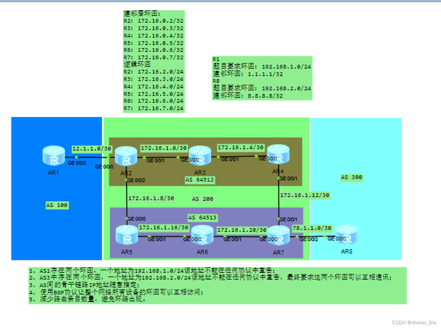
题目
1、AS1存在两个环回,一个地址为192.168.1.0/24该地址不能在任何协议中宣告;
2、AS3中存在两个环回,一个地址为192.168.2.0/24该地址不能在任何协议中宣告,最终要求这两个环回可以互相通讯;
3、AS间的骨干链路IP地址随意指定;
4、使用BGP协议让整个网络所有设备的环回可以互相访问;
5、减少路由条目数量,避免环路出现。
实验步骤
第一步、IP地址规划
网段划分如下
AS2在172.16.0.0/16网段划分
建邻居环回:
R2:172.16.0.2/32
R3:172.16.0.3/32
R4:172.16.0.4/32
R5:172.16.0.5/32
R6:172.16.0.6/32
R7:172.16.0.7/32
逻辑环回
R2:172.16.2.0/24
R3:172.16.3.0/24
R4:172.16.4.0/24
R5:172.16.5.0/24
R6:172.16.6.0/24
R7:172.16.7.0/24
骨干链路:
R2-R3:172.16.1.0/30
R3-R4:172.16.1.4/30
R2-R5:172.16.1.8/30
R4:R7:172.16.1.12/30
R5-R6:172.16.1.16/30
R6-R7:172.16.1.20/30
R1
题目要求环回:192.168.1.0/24
环回:1.1.1.0/24
R8
题目要求环回:192.168.2.0/24
环回:8.8.8.0/24
AS之间的骨干链路
R1-R2:12.1.1.0/30
R7-R8:78.1.1.0/30
设备接口IP地址如
| 设备 | 接口 | IP地址 |
| R1 | G0/0/0 | 12.1.1.1/30 |
| Lo0 | 1.1.1.1/24 | |
| Lo1 | 192.168.1.1/24 | |
| R2 | G0/0/0 | 12.1.1.2/30 |
| G0/0/1 | 172.16.1.1/30 | |
| G0/0/2 | 172.16.1.9/30 | |
| Lo0 | 172.16.0.2/32 | |
| Lo1 | 172.16.2.1/24 | |
| R3 | G0/0/0 | 172.16.1.2/30 |
| G0/0/1 | 172.16.1.5/30 | |
| Lo0 | 172.16.0.3/32 | |
| Lo1 | 172.16.3.1/24 | |
| R4 | G0/0/0 | 172.16.1.6/30 |
| G0/0/1 | 172.16.1.13/30 | |
| Lo0 | 172.16.0.4/32 | |
| Lo1 | 172.16.4.1/32 | |
| R5 | G0/0/0 | 172.16.1.10/30 |
| G0/0/1 | 172.16.1.17/30 | |
| Lo0 | 172.16.0.5/32 | |
| Lo1 | 172.16.5.1/24 | |
| R6 | G0/0/0 | 172.16.1.18/30 |
| G0/0/1 | 172.16.1.21/30 | |
| Lo0 | 172.16.0.6/32 | |
| Lo1 | 172.16.6.1/24 | |
| R7 | G0/0/0 | 172.16.1.22/30 |
| G0/0/1 | 172.16.1.14/30 | |
| G0/0/2 | 78.1.1.7/30 | |
| Lo0 | 172.16.0.7/32 | |
| Lo1 | 172.16.7.1/30 | |
| R8 | G0/0/0 | 78.1.1.1.8/30 |
| Lo0 | 8.8.8.8/24 | |
| Lo1 | 192.168.2.1/24 |
第二步、接口IP地址配置
R1
<Huawei>system-view
[Huawei]sysname R1
[R1]int g0/0/0
[R1-GigabitEthernet0/0/0]ip address 12.1.1.1 24
[R1-GigabitEthernet0/0/0]int lo0
[R1-LoopBack0]ip address 1.1.1.1 24
[R1-LoopBack0]int lo1
[R1-LoopBack1]ip address 192.168.1.1 24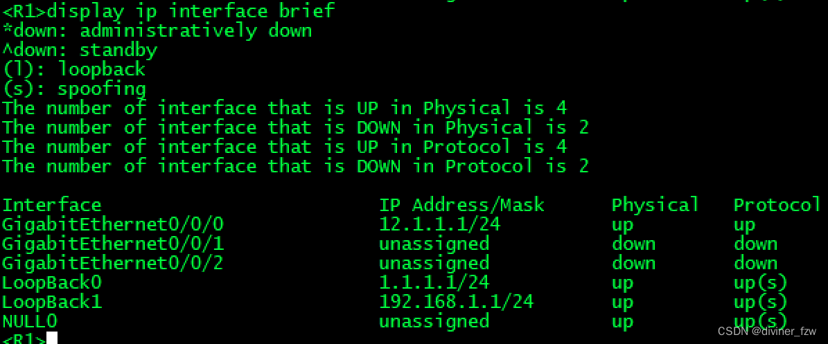
R2
<Huawei>system-view
[Huawei]sysname R2
[R2]int g0/0/0
[R2-GigabitEthernet0/0/0]ip address 12.1.1.2 24
[R2-GigabitEthernet0/0/0]int g0/0/1
[R2-GigabitEthernet0/0/1]ip address 172.16.1.1 30
[R2-GigabitEthernet0/0/1]int g0/0/2
[R2-GigabitEthernet0/0/2]ip address 172.16.1.9 30
[R2-GigabitEthernet0/0/2]int lo0
[R2-LoopBack0]ip address 172.16.0.2 32
[R2-LoopBack0]int lo1
[R2-LoopBack1]ip address 172.16.2.1 24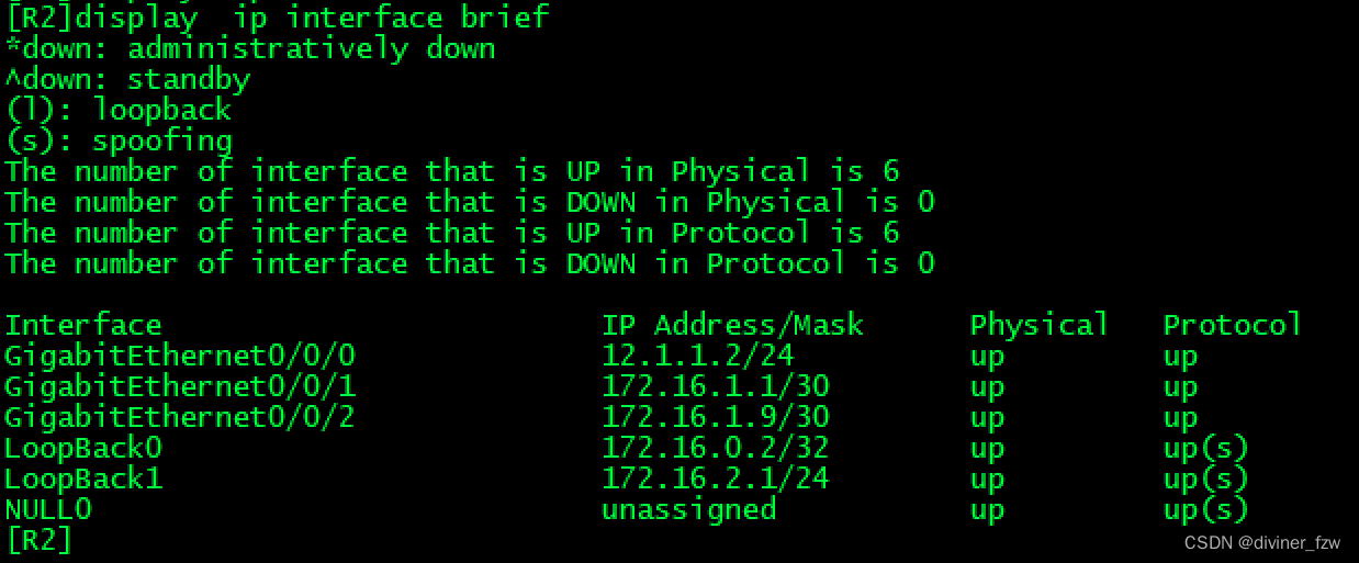
R3
<Huawei>system-view
[Huawei]sysname R3
[R3]int g0/0/0
[R3-GigabitEthernet0/0/0]ip address 172.16.1.2 30
[R3-GigabitEthernet0/0/0]int g0/0/1
[R3-GigabitEthernet0/0/1]ip address 172.16.1.5 30
[R3-GigabitEthernet0/0/1]int lo0
[R3-LoopBack0]ip address 172.16.0.3 32
[R3-LoopBack0]in lo1
[R3-LoopBack1]ip address 172.16.3.1 24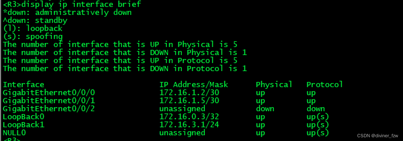
R4
<Huawei>system-view
[Huawei]sysname R4
[R4]int g0/0/0
[R4-GigabitEthernet0/0/0]ip address 172.16.1.6 30
[R4-GigabitEthernet0/0/0]in g0/0/1
[R4-GigabitEthernet0/0/1]ip address 172.16.1.13 30
[R4-GigabitEthernet0/0/1]int lo0
[R4-LoopBack0]ip address 172.16.0.4 32
[R4-LoopBack0]int lo1
[R4-LoopBack1]ip address 172.16.4.1 24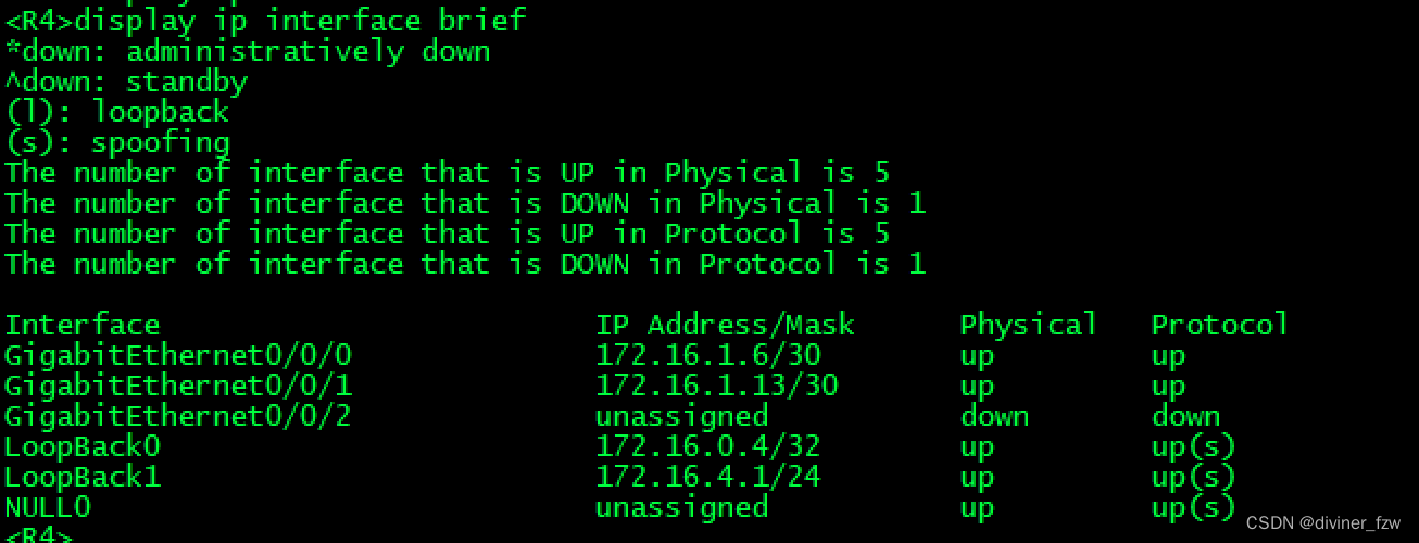
R5
<Huawei>system-view
[Huawei]sysname R5
[R5]int g0/0/0
[R5-GigabitEthernet0/0/0]ip address 172.16.1.10 30
[R5-GigabitEthernet0/0/0]int g0/0/1
[R5-GigabitEthernet0/0/1]ip address 172.16.1.17 30
[R5-GigabitEthernet0/0/1]int lo0
[R5-LoopBack0]ip address 172.16.0.5 32
[R5-LoopBack0]int lo1
[R5-LoopBack1]ip address 172.16.5.1 24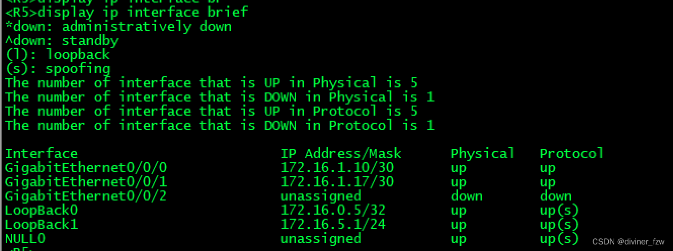
R6
<Huawei>system-view
[Huawei]sysname R6
[R6]int g0/0/0
[R6-GigabitEthernet0/0/0]ip address 172.16.1.18 30
[R6-GigabitEthernet0/0/0]int g0/0/1
[R6-GigabitEthernet0/0/1]ip address 172.16.1.21 30
[R6-GigabitEthernet0/0/1]int g0/0/1
[R6-GigabitEthernet0/0/1]int lo0
[R6-LoopBack0]ip address 172.16.0.6 32
[R6-LoopBack0]int lo1
[R6-LoopBack1]ip address 172.16.6.1 24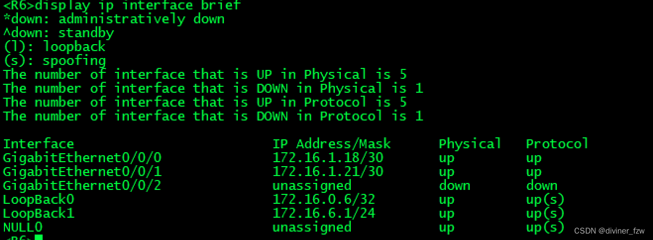
R7
<Huawei>system-view
[Huawei]sysname R7
[R7]int g0/0/0
[R7-GigabitEthernet0/0/0]ip address 172.16.1.22 30
[R7-GigabitEthernet0/0/0]in g0/0/1
[R7-GigabitEthernet0/0/1]ip address 172.16.1.14 30
[R7-GigabitEthernet0/0/1]int g0/0/2
[R7-GigabitEthernet0/0/2]ip address 78.1.1.7 24
[R7-GigabitEthernet0/0/2]int lo0
[R7-LoopBack0]ip address 172.16.0.7 32
[R7-LoopBack0]int lo1
[R7-LoopBack1]ip address 172.16.7.1 24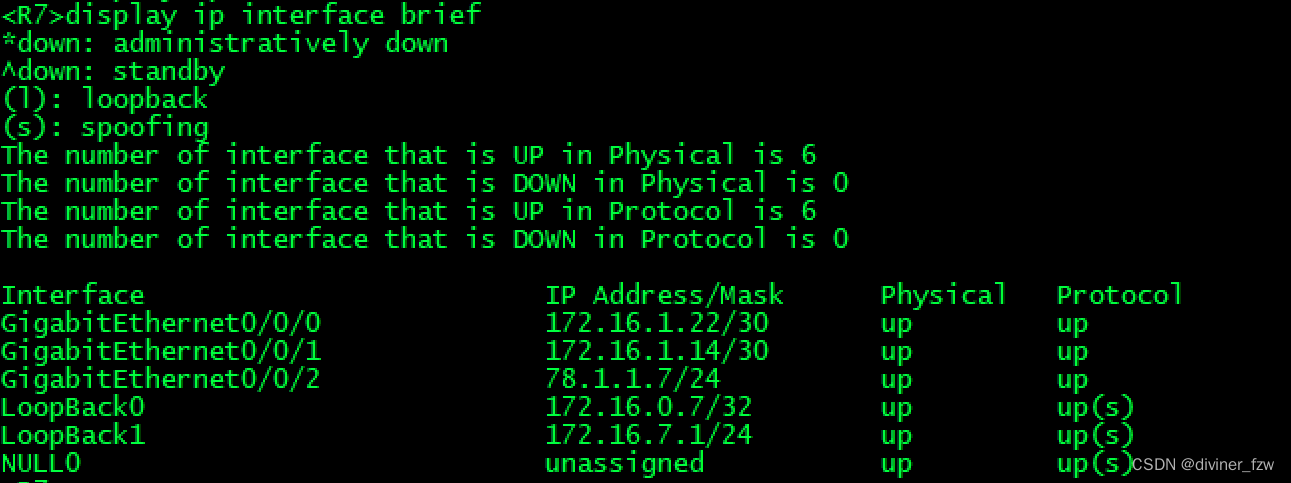
R8
<Huawei>system-view
[Huawei]sysname R8
[R8]int g0/0/0
[R8-GigabitEthernet0/0/0]ip address 78.1.1.8 24
[R8-GigabitEthernet0/0/0]int lo0
[R8-LoopBack0]ip address 8.8.8.8 24
[R8-LoopBack0]int lo1
[R8-LoopBack1]ip address 192.168.2.1 24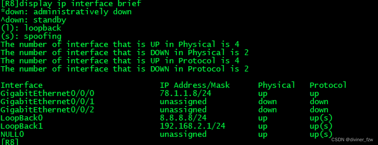
第三步、写静态路由
要启动BGP需要先有能够到达的路由
R1-R2
[R1]ip route-static 172.16.0.2 32 12.1.1.2
[R2]ip route-static 1.1.1.1 32 12.1.1.1
R7-R8
[R7]ip route-static 8.8.8.8 32 78.1.1.8
[R8]ip route-static 172.16.0.7 32 78.1.1.7
第四步、AS 200启用IBGP
IBGP使用的是OSPF
R2
[R2]ospf 1 router-id 2.2.2.2
[R2-ospf-1]area 0
[R2-ospf-1-area-0.0.0.0]network 172.16.2.0 0.0.255.255 
R3
[R3]ospf 1 router-id 3.3.3.3
[R3-ospf-1]area 0
[R3-ospf-1-area-0.0.0.0]network 172.16.3.0 0.0.255.255
R4
[R4]ospf 1 router-id 4.4.4.4
[R4-ospf-1]area 0
[R4-ospf-1-area-0.0.0.0]network 172.16.4.0 0.0.255.255
R5
[R5]ospf 1 router-id 5.5.5.5
[R5-ospf-1]area 0
[R5-ospf-1-area-0.0.0.0]network 172.16.5.0 0.0.255.255
R6
[R6]ospf 1 router-id 6.6.6.6
[R6-ospf-1]area 0
[R6-ospf-1-area-0.0.0.0]network 172.16.6.0 0.0.255.255
R7
[R7]ospf 1 router-id 7.7.7.7
[R7-ospf-1]area 0
[R7-ospf-1-area-0.0.0.0]network 172.16.7.0 0.0.255.255
第五步、修改环回接口OSPF网络类型
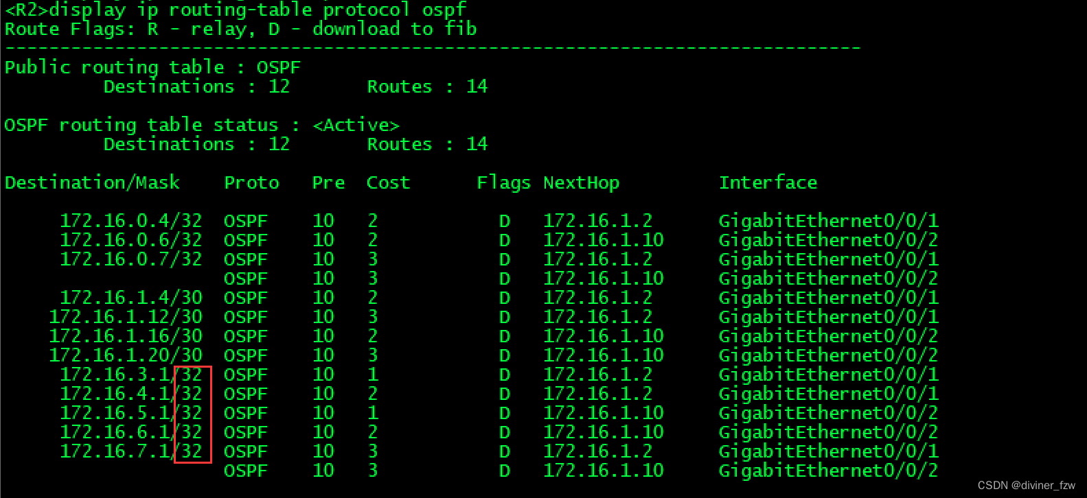
因为环回接口在OSPF宣告默认类型为p2mp,其他路由器学习到网段就为32位掩码,所以这里需要修改环回接口OSPF网络类型为broadcast。
先查看其他路由器通过OSPF学到其他网段的环回网段位32位
#R2
[R2]int lo1
[R2-LoopBack1]ospf network-type broadcast
#R3
[R3]int lo1
[R3-LoopBack1]ospf network-type broadcast
#R4
[R4]int lo1
[R4-LoopBack1]ospf network-type broadcast
#R5
[R5]int lo1
[R5-LoopBack1]ospf network-type broadcast
#R6
[R6]int lo1
[R6-LoopBack1]ospf network-type broadcast
#R7
[R7]int lo1
[R7-LoopBack1]ospf network-type broadcast
修改后再进行查看,学习到的就是那个网段了

第六步、启动BGP建邻
在建邻居的时候同时修改本地路由器传递,便于后期路由传递变优。
R1
[R1]bgp 100
[R1-bgp]router-id 1.1.1.1
[R1-bgp]peer 12.1.1.2 as-number 200
R2
R2]bgp 64512
[R2-bgp]router-id 2.2.2.2
[R2-bgp]confederation id 200
[R2-bgp]peer 12.1.1.1 as-number 100
[R2-bgp]peer 172.16.0.3 as-number 64512
[R2-bgp]peer 172.16.0.3 connect-interface lo0
[R2-bgp]peer 172.16.0.3 next-hop-local
[R2-bgp]confederation peer-as 64513
[R2-bgp]peer 172.16.0.5 as-number 64513
[R2-bgp]peer 172.16.0.5 connect-interface lo0
[R2-bgp]peer 172.16.0.5 ebgp-max-hop 2

R3
[R3]bgp 64512
[R3-bgp]router-id 3.3.3.3
[R3-bgp]confederation id 200
[R3-bgp]peer 172.16.0.2 as-number 64512
[R3-bgp]peer 172.16.0.2 connect-interface lo0
[R3-bgp]peer 172.16.0.2 next-hop-local
[R3-bgp]peer 172.16.0.4 as-number 64512
[R3-bgp]peer 172.16.0.4 connect-interface lo0
[R3-bgp]peer 172.16.0.4 next-hop-local
R4
[R4]bgp 64512
[R4-bgp]router-id 4.4.4.4
[R4-bgp]confederation id 200
[R4-bgp]peer 172.16.0.3 as-number 64512
[R4-bgp]peer 172.16.0.3 connect-interface lo0
[R4-bgp]peer 172.16.0.3 next-hop-local
[R4-bgp]confederation peer-as 64513
[R4-bgp]peer 172.16.0.7 as-number 64513
[R4-bgp]peer 172.16.0.7 connect-interface lo0
[R4-bgp]peer 172.16.0.7 ebgp-max-hop 2
R5
[R5]bgp 64513
[R5-bgp]router-id 5.5.5.5
[R5-bgp]confederation id 200
[R5-bgp]confederation peer-as 64512
[R5-bgp]peer 172.16.0.2 as-number 64512
[R5-bgp]peer 172.16.0.2 connect-interface lo0
[R5-bgp]peer 172.16.0.2 ebgp-max-hop 2
[R5-bgp]peer 172.16.0.6 as-number 64513
[R5-bgp]peer 172.16.0.6 connect-interface lo0
[R5-bgp]peer 172.16.0.6 next-hop-local
R6
[R6]bgp 64513
[R6-bgp]router-id 6.6.6.6
[R6-bgp]confederation id 200
[R6-bgp]peer 172.16.0.5 as-number 64513
[R6-bgp]peer 172.16.0.5 connect-interface lo0
[R6-bgp]peer 172.16.0.5 next-hop-local
[R6-bgp]peer 172.16.0.7 as-number 64513
[R6-bgp]peer 172.16.0.7 connect-interface lo0
[R6-bgp]peer 172.16.0.7 next-hop-local
R7
[R7]bgp 64513
[R7-bgp]router-id 7.7.7.7
[R7-bgp]confederation id 200
[R7-bgp]peer 78.1.1.8 as-number 300
[R7-bgp]peer 172.16.0.6 as-number 64513
[R7-bgp]peer 172.16.0.6 connect-interface lo0
[R7-bgp]peer 172.16.0.6 next-hop-local
[R7-bgp]confederation peer-as 64512
[R7-bgp]peer 172.16.0.4 as-number 64512
[R7-bgp]peer 172.16.0.4 connect-interface lo0
[R7-bgp]peer 172.16.0.4 ebgp-max-hop 2
R8
[R8]bgp 300
[R8-bgp]router-id 8.8.8.8
[R8-bgp]peer 78.1.1.7 as-number 200
第七步、BGP宣告
R1上进行宣告1.1.1.0/24
[R1]bgp 100
[R1-bgp]network 1.1.1.0 24
然后进行查看在R3上面进行查看,发现R3是学到这条路由了。

再去R4上面查看,发现没有学习到这条路由。

那么我们就需要使用反射器来满足要求,为反射器指定一个客户端,因为两个非客户端是不会进行传递路由,只有非->客、客->客;还有就是在ebgp和ibgp之间会进行传递。
选用一个路由器作为反射器,我这里是指定的R3为反射器,R1为客户端。
[R3]bgp 64512
[R3-bgp]peer 172.16.0.2 reflect-client
再去R4上面查看,以及收到这条路由。

在去R8上面看也可以看见这条路由,因为到R4会用过EBGP传递给R7,R7在由EBGP关系传给R8。

R8上进行宣告8.8.8.0/24网段
也是同样的需要用到一个反射器指定R7为客户端,不然R5也会没有8.8.8.0/24这个网段
[R6]bgp 64513
[R6-bgp]peer 172.16.0.7 reflect-client
在R5上面进行查看

在R1上面进行查看

在AS200 进行宣告
AS200汇总指向空接口, 然后再对网段进行BGP宣告。这样便于其他路由器也只会有一条路由。
R2
[R2]ip route-static 172.16.0.0 21 NULL 0
[R2]bgp 64512
[R2-bgp]network 172.16.0.0 21
去R1和R8上面查看,只学到一条路由,这样也减少了路由条目


为了不在R2上面找到空接口才把黑洞路由丢掉,我们在R7上面也进行一个同样的操作,这样也可以避免造成AS内部的资源消耗。
R7
[R7]ip route-static 172.16.0.0 21 NULL 0
[R7]bgp 64513
[R7-bgp]network 172.16.0.0 21
第八步、建立隧道
让192.168.1.0 和 192.168.2.0这两个网段不能宣告,但是又能互相访问,可以采用Tunnel隧道来解决,因为我们的物理线路以实现全网可达,然后通过静态路由指向对方网段,把下一跳扔进隧道里面。
R1
[R1]int t0/0/0
[R1-Tunnel0/0/0]ip address 10.1.1.1 24
[R1-Tunnel0/0/0]tunnel-protocol gre
[R1-Tunnel0/0/0]source 1.1.1.1
[R1-Tunnel0/0/0]destination 8.8.8.8
[R1-Tunnel0/0/0]q
[R1]ip route-static 192.168.2.0 24 Tunnel 0/0/0
R8
[R8]int t0/0/0
[R8-Tunnel0/0/0]ip address 10.1.1.2 24
[R8-Tunnel0/0/0]tunnel-protocol gre
[R8-Tunnel0/0/0]source 8.8.8.8
[R8-Tunnel0/0/0]destination 1.1.1.1
[R8-Tunnel0/0/0]q
[R8]ip route-static 192.168.1.0 24 Tunnel 0/0/0
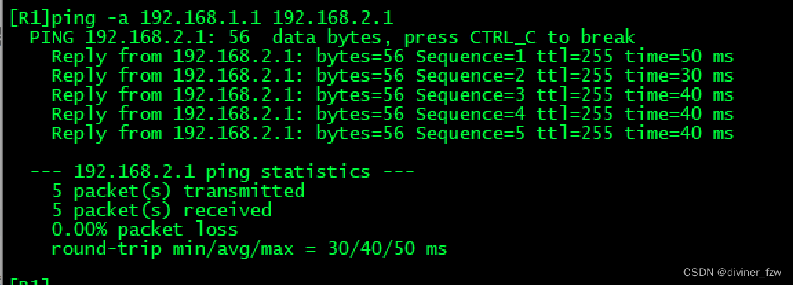
进行一个测试:
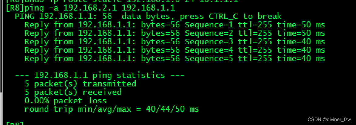
第九步、测试
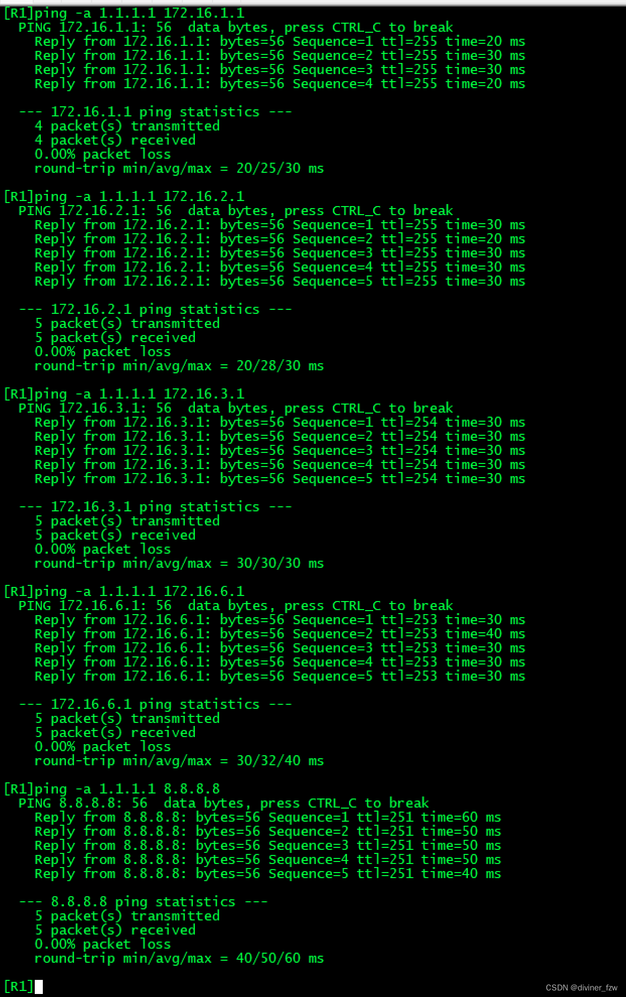
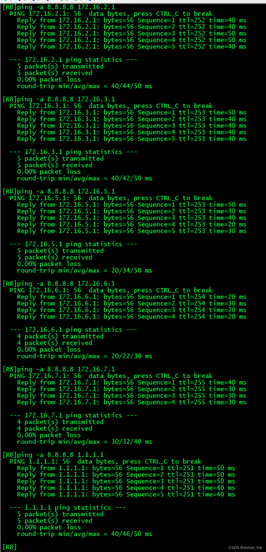
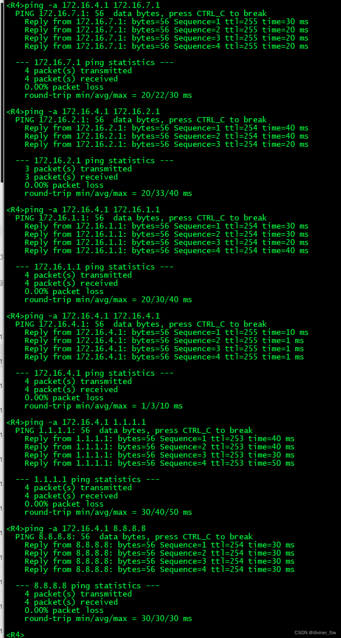
测试是实现各环回可以互相访问。
