作用:
提供网关冗余功能,保证出口网关的高可用型。当网关发生故障的时候,能让PC快速的切换。
概念:
通过VRRP协议创建出一个虚拟网关,主用路由器down之后备用路由器能马上接替其主的位置,继续提供出口网关服务。
实验需求:
在 LSW1 与 LSW2 的 vlan 10 和 vlan 20 上配置 vrrp 且 SW1 与 SW2 的 vird 组分别为 10、 20,virtual-ip 分别为 192.168.1.254、192.168.2.254,其中 LSW1 为 vlan 10 的 master, LSW2 为 vlan 20 的 master,LSW1 为 vlan 20 的 backup,LSW2 为 vlan 10 的 backup;master 的优先级为 150,backup 的优先级为 120
配置思路:
1.配置ip地址
2.在三层交换机使用VRRP协议创建虚拟网关
3.监测上行接口状态,实现主备切换
实验拓扑:

具体配置:
PC1:ip:192.168.1.1/24 网关:192.168.1.254
PC2:ip:192.168.1.2/24 网关:192.168.1.254
PC3:ip:192.168.2.1/24 网关:192.168.2.254
1.vlan划分
[SW3]vlan b 10 20
Info: This operation may take a few seconds. Please wait for a moment...done.
[SW3]int e0/0/1
[SW3-Ethernet0/0/1]po l t
[SW3-Ethernet0/0/1]po t a v 10 20
[SW3-Ethernet0/0/1]int e0/0/2
[SW3-Ethernet0/0/2]po l t
[SW3-Ethernet0/0/2]po t a v 10 20
[SW3-Ethernet0/0/2]int e0/0/3
[SW3-Ethernet0/0/3]po l a
[SW3-Ethernet0/0/3]po d v 10
[SW3-Ethernet0/0/3]int e0/0/4
[SW3-Ethernet0/0/4]po l a
[SW3-Ethernet0/0/4]po d v 10
[SW3-Ethernet0/0/4]int e0/0/5
[SW3-Ethernet0/0/5]po l a
[SW3-Ethernet0/0/5]po d v 20
[SW1]vlan b 10 20 111
[SW1]int g0/0/2
[SW1-GigabitEthernet0/0/2]po l t
[SW1-GigabitEthernet0/0/2]po t a v 10 20
[SW1-GigabitEthernet0/0/2]int vlan 10
[SW1-Vlanif10]ip add 192.168.1.253 24
[SW1-Vlanif10]int vlan 20
[SW1-Vlanif20]ip add 192.168.2.253 24
[SW1-Vlanif20]int vlan 111
[SW1-Vlanif111]ip add 10.1.1.1 24
[SW1-Vlanif111]int g0/0/1
[SW1-GigabitEthernet0/0/1]po l a
[SW1-GigabitEthernet0/0/1]po d v 111
[SW2]vlan b 10 20 222
Info: This operation may take a few seconds. Please wait for a moment...done.
[SW2]int g0/0/2
[SW2-GigabitEthernet0/0/2]po l t
[SW2-GigabitEthernet0/0/2]po t a v 10 20
[SW2-GigabitEthernet0/0/2]int vlan 10
[SW2-Vlanif10]ip add 192.168.1.252 24
[SW2-Vlanif10]int vlan 20
[SW2-Vlanif20]ip add 192.168.2.252 24
[SW2-Vlanif20]int vlan 222
[SW2-Vlanif222]ip add 20.1.1.1 24
[SW2-Vlanif222]int g0/0/1
[SW2-GigabitEthernet0/0/1]po l a
[SW2-GigabitEthernet0/0/1]po d v 222
2.端口聚合配置
[SW1]int Eth-Trunk 10
[SW1-Eth-Trunk10]trunk
[SW1-Eth-Trunk10]trunkport g0/0/3
[SW1-Eth-Trunk10]trunkport g0/0/4
[SW1-Eth-Trunk10]po l t
[SW1-Eth-Trunk10]po t a v 10 20
[SW2]int Eth-Trunk 10
[SW2-Eth-Trunk10]trunkport g0/0/3
Info: This operation may take a few seconds. Please wait for a moment...done.
[SW2-Eth-Trunk10]trunkport g0/0/4
Info: This operation may take a few seconds. Please wait for a moment...done.
[SW2-Eth-Trunk10]po l t
[SW2-Eth-Trunk10]po t a v 10 20
3.VRRP配置
[SW1]int vlan 10
[SW1-Vlanif10]vrrp vrid 10 virtual-ip 192.168.1.254    //进程号为10,虚拟ip为192.168.1.254
[SW1-Vlanif10]vrrp vrid 10 priority 150                //优先级为150

[SW1]int vlan 20
[SW1-Vlanif20]vrrp vrid 20 virtual-ip 192.168.2.254
[SW1-Vlanif20]vrrp vrid 20 priority 120
[SW2]int vlan 10
[SW2-Vlanif10]vrrp vrid 10 virtual-ip 192.168.1.254
[SW2-Vlanif10]vrrp vrid 10 priority 120
[SW2-Vlanif10]int vlan 20
[SW2-Vlanif20]vrrp vrid 20 virtual-ip 192.168.2.254.
[SW2-Vlanif20]vrrp vrid 20 priority 150
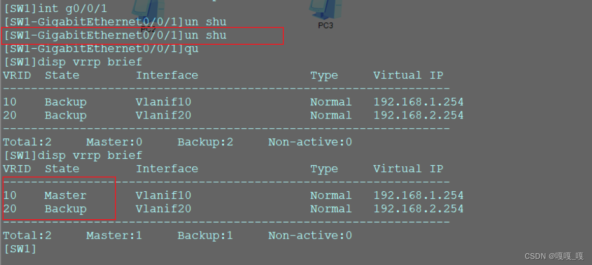
用disp vrrp brief查看此时vrrp状态
可以看到在SW1上vlan10为主动,在SW2上vlan20为主动


4.监测上行接口状态,通过降低优先级实现主备切换
如果交换机down,那么上行的g0/0/1接口也会跟着关闭,因此通过监测g0/0/1接口的状态来判断交换机是否能继续转发三层流量
[SW1]int vlan 10
[SW1-Vlanif10]vrrp vrid 10 track interface g0/0/1 reduced 50 //上行接口出现损坏,优先级降低50
[SW2]int vlan 20
[SW2-Vlanif20]vrrp vrid 20 track int g0/0/1 reduced 50
 5.给路由器配置ip地址
[R1]int g0/0/0
[R1-GigabitEthernet0/0/0]
[R1-GigabitEthernet0/0/0]ip add 10.1.1.2 24
[R1-GigabitEthernet0/0/0]int g0/0/1
[R1-GigabitEthernet0/0/1]ip add 20.1.1.2 24
配置静态路由
[R1]ip route-static 0.0.0.0 0 10.1.1.1
[R1]ip route-static 0.0.0.0 0 20.1.1.1
[SW1]ip route-static 20.1.1.0 24 10.1.1.2[SW2]ip route-static 10.1.1.0 24 20.1.1.2测试连通性
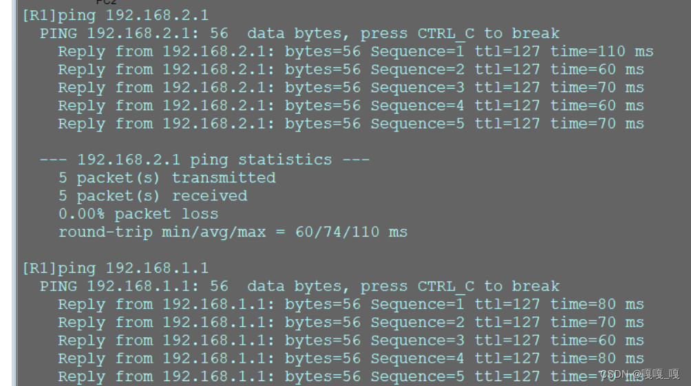
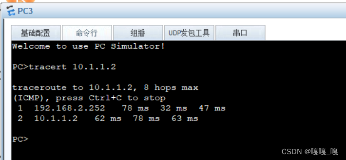
查看PC1到R1发包路径
是走的SW1

是走的SW2