直流无刷电机FOC控制算法 理论到实践 —— 实践
文章目录
- 直流无刷电机FOC控制算法 理论到实践 —— 实践
- 1. 前言
- 2. FOC控制整体流程
- 3. FOC实现
- 3.1 定时器实现
- 3.1.1 代码实现
- 3.2 角度识别
- 3.2.1 机械角度计算
- 3.2.2 电角度计算
- 3.2.3 代码实现
- 3.3 角度识别初步验证
- 3.4 电流采集
- 3.5 Clark和Park变化
- 3.5.1 代码实现
- 3.6 电流环PID计算
- 3.6.1 代码实现
- 3.7 反Park变化及SVPWM
- 3.7.1 代码实现
- 3.8 反Park变化及SVPWM算法验证
- 3.8.1 代码实现
- 3.9 角度识别深度验证
- 3.10 电流环PID调节
- 4. 速度环PID实现
- 5. 结束语
1. 前言
关于直流无刷电机FOC控制算法的理论章节,本人已经在前两章进行过详细说明,大家可以自行进行阅读,请务必了解过理论之后再来学习如何具体进行实现。
直流无刷电机FOC控制算法 理论到实践 —— 理论(一)
直流无刷电机FOC控制算法 理论到实践 —— 理论(二)
本章节主要讨论采用MCU微控制器如何具体实现直流无刷电机的FOC控制
2. FOC控制整体流程
首先我们回顾下完整的FOC控制算法的实现流程,主要分为以下几大步: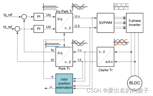
- 采集电机三相相电流 Ia Ib Ic
- 将三相相电流通过 Clark 变化得到 Iα Iβ
- 将 Iα Iβ 通过 Park 变化得到 Id Iq
- 根据 Id Iq 和目标 Id_target Iq_target 进行 PID 计算得到 Uq Ud (电流环)
- 将 Uq Ud 通过反 Park 变换得到 Uα Uβ
- 将 Uα Uβ 作为SVPWM的输入,得到三路半桥的PWM输出定时器的比较寄存器值CCR
3. FOC实现
本文所采用的硬件说明:
- 主控 MCU 以 GD32F4xx
- 电机反馈信号为正交编码信号+绝对位置磁传感器信号
- 正交编码器分辨率为1024
3.1 定时器实现
驱动直流无刷电机需要控制三个半桥驱动电路,驱动三个半桥,根据硬件设计不同,有的只需要三路PWM,之后通过半桥驱动芯片(如IR2104)产生两路互补的PWM;有的则需要直接输出三路互补PWM,实际由硬件电路决定,此处我们电路需要我们输出三路互补的PWM,因此首先第一步便是配置控制器MCU输出三路互补的PWM。
根据我们之前的分析,实现FOC的控制,大体可以概括为通过采集电机的实时三相电流以及电机实时的角度,计算电机当前所在位置及扇区,通过控制三路半桥在一个周期内的导通去生成一个合成磁力,此合成磁力始终与电机磁场呈90°相切,从而实现电机的驱动控制,因此为了尽可能的保证合成磁力与电机磁场始终保持在90°,在每次生成合成磁力驱动之后均需要实时调整,因此我们的FOC控制需要在每个PWM周期进行一次,因此FOC的控制算法几乎全部在定时器的更新中断内实现。
此外由于电机反馈信号还包含正交编码信号及绝对位置磁传感器信号,均需完成信号的采集,这两种均可以采用定时器来实现,分别配置定时器为编码器模式和输入捕获模式即可。
3.1.1 代码实现
- 配置定时器输出三路互补的PWM,完成三路半桥的驱动,同时打开定时器的更新中断,在更新中断内完成FOC计算:
static void pwm_gpio_config(void)
{
    rcu_periph_clock_enable(RCU_GPIOA);
    rcu_periph_clock_enable(RCU_GPIOB);
    rcu_periph_clock_enable(RCU_GPIOC);

    gpio_mode_set(GPIOA, GPIO_MODE_AF, GPIO_PUPD_NONE, GPIO_PIN_7);
    gpio_output_options_set(GPIOA, GPIO_OTYPE_PP, GPIO_OSPEED_50MHZ,GPIO_PIN_7);

    gpio_mode_set(GPIOB, GPIO_MODE_AF, GPIO_PUPD_NONE, GPIO_PIN_0 | GPIO_PIN_1);
    gpio_output_options_set(GPIOB, GPIO_OTYPE_PP, GPIO_OSPEED_50MHZ, GPIO_PIN_0 | GPIO_PIN_1);

    gpio_mode_set(GPIOC, GPIO_MODE_AF, GPIO_PUPD_NONE, GPIO_PIN_6 | GPIO_PIN_7 | GPIO_PIN_8);
    gpio_output_options_set(GPIOC, GPIO_OTYPE_PP, GPIO_OSPEED_50MHZ, GPIO_PIN_6 | GPIO_PIN_7 | GPIO_PIN_8);

    gpio_af_set(GPIOA, GPIO_AF_3, GPIO_PIN_7);
    gpio_af_set(GPIOB, GPIO_AF_3, GPIO_PIN_0);
    gpio_af_set(GPIOB, GPIO_AF_3, GPIO_PIN_1);
    gpio_af_set(GPIOC, GPIO_AF_3, GPIO_PIN_6);
    gpio_af_set(GPIOC, GPIO_AF_3, GPIO_PIN_7);
    gpio_af_set(GPIOC, GPIO_AF_3, GPIO_PIN_8);
}

static void pwm_timer_config(void)
{
    timer_oc_parameter_struct timer_ocintpara = {0};
    timer_parameter_struct timer_initpara = {0};
    timer_break_parameter_struct timer_breakpara = {0};

    rcu_periph_clock_enable(RCU_TIMER7);
    rcu_timer_clock_prescaler_config(RCU_TIMER_PSC_MUL4);
    timer_deinit(TIMER7);

    /* TIMER1 configuration */
    timer_initpara.prescaler         = 12 - 1;
    timer_initpara.alignedmode       = TIMER_COUNTER_CENTER_UP;
    timer_initpara.counterdirection  = TIMER_COUNTER_UP;
    timer_initpara.period            = 1000-1;
    timer_initpara.clockdivision     = TIMER_CKDIV_DIV1;
    timer_initpara.repetitioncounter = 1;
    timer_init(TIMER7, &timer_initpara);

     /* CH0/CH0N,CH1/CH1N and CH2/CH2N configuration in pwm0 mode */
    timer_ocintpara.outputstate  = TIMER_CCX_DISABLE;
    timer_ocintpara.outputnstate = TIMER_CCXN_DISABLE;
    timer_ocintpara.ocpolarity   = TIMER_OC_POLARITY_HIGH;
    timer_ocintpara.ocnpolarity  = TIMER_OCN_POLARITY_HIGH;
    timer_ocintpara.ocidlestate  = TIMER_OC_IDLE_STATE_LOW;
    timer_ocintpara.ocnidlestate = TIMER_OCN_IDLE_STATE_HIGH;

    timer_channel_output_config(TIMER7,TIMER_CH_0,&timer_ocintpara);
    timer_channel_output_config(TIMER7,TIMER_CH_1,&timer_ocintpara);
    timer_channel_output_config(TIMER7,TIMER_CH_2,&timer_ocintpara);

    timer_channel_output_pulse_value_config(TIMER7,TIMER_CH_0,0);
    timer_channel_output_mode_config(TIMER7,TIMER_CH_0,TIMER_OC_MODE_PWM0);
    timer_channel_output_shadow_config(TIMER7,TIMER_CH_0,TIMER_OC_SHADOW_ENABLE);

    timer_channel_output_pulse_value_config(TIMER7,TIMER_CH_1,0);
    timer_channel_output_mode_config(TIMER7,TIMER_CH_1,TIMER_OC_MODE_PWM0);
    timer_channel_output_shadow_config(TIMER7,TIMER_CH_1,TIMER_OC_SHADOW_ENABLE);

    timer_channel_output_pulse_value_config(TIMER7,TIMER_CH_2,0);
    timer_channel_output_mode_config(TIMER7,TIMER_CH_2,TIMER_OC_MODE_PWM0);
    timer_channel_output_shadow_config(TIMER7,TIMER_CH_2,TIMER_OC_SHADOW_ENABLE);

    /* automatic output enable, break, dead time and lock configuration*/
    timer_breakpara.runoffstate         = TIMER_ROS_STATE_ENABLE;
    timer_breakpara.ideloffstate        = TIMER_IOS_STATE_ENABLE ;
    timer_breakpara.deadtime            = 84;   /* 死区时间340ns */
    timer_breakpara.breakpolarity       = TIMER_BREAK_POLARITY_LOW;
    timer_breakpara.outputautostate     = TIMER_OUTAUTO_ENABLE;
    timer_breakpara.protectmode         = TIMER_CCHP_PROT_OFF;
    timer_breakpara.breakstate          = TIMER_BREAK_DISABLE;
    timer_break_config(TIMER7, &timer_breakpara);

    timer_primary_output_config(TIMER7, ENABLE);

    /* TIMER7 channel clear update interrupt */
    timer_interrupt_flag_clear(TIMER7, TIMER_INT_FLAG_UP);
    /* TIMER7 channel control update interrupt enable */
    timer_interrupt_enable(TIMER7, TIMER_INT_UP);
    /* TIMER7 break interrupt disable */
    timer_interrupt_disable(TIMER7,TIMER_INT_BRK);

    /* TIMER7 counter enable */
    timer_disable(TIMER7);
}

static void pwm_nvic_config(void)
{
    nvic_irq_enable(TIMER7_UP_TIMER12_IRQn, 2, 1);
}


void set_motor_break(uint8_t state)
{
    if (state != 0)
        timer_break_enable(TIMER7);
    else
        timer_break_disable(TIMER7);
}

/**
 * @brief 设置电机PWM输出使能
 *
 * @note 注意,此函数会关闭输出之后重新配置,因此禁止在pwm更新中断内调用,否则会影响输出波形
 * @param state
 */
void set_motor_pwm_output(uint8_t state)
{
    if (state != 0) {
        timer_channel_output_state_config(TIMER7,TIMER_CH_0,TIMER_CCX_ENABLE);
        timer_channel_output_state_config(TIMER7,TIMER_CH_1,TIMER_CCX_ENABLE);
        timer_channel_output_state_config(TIMER7,TIMER_CH_2,TIMER_CCX_ENABLE);
        timer_channel_complementary_output_state_config(TIMER7,TIMER_CH_0,TIMER_CCXN_ENABLE);
        timer_channel_complementary_output_state_config(TIMER7,TIMER_CH_1,TIMER_CCXN_ENABLE);
        timer_channel_complementary_output_state_config(TIMER7,TIMER_CH_2,TIMER_CCXN_ENABLE);
    } else {
        timer_channel_output_state_config(TIMER7,TIMER_CH_0,TIMER_CCX_DISABLE);
        timer_channel_output_state_config(TIMER7,TIMER_CH_1,TIMER_CCX_DISABLE);
        timer_channel_output_state_config(TIMER7,TIMER_CH_2,TIMER_CCX_DISABLE);
        timer_channel_complementary_output_state_config(TIMER7,TIMER_CH_0,TIMER_CCXN_DISABLE);
        timer_channel_complementary_output_state_config(TIMER7,TIMER_CH_1,TIMER_CCXN_DISABLE);
        timer_channel_complementary_output_state_config(TIMER7,TIMER_CH_2,TIMER_CCXN_DISABLE);
    }
}

void set_motor_pwm_duty(uint8_t channel, float duty)
{
    switch (channel) {
        case 0:
            timer_channel_output_pulse_value_config(TIMER7, TIMER_CH_0, duty);
            break;
        case 1:
            timer_channel_output_pulse_value_config(TIMER7, TIMER_CH_1, duty);
            break;
        case 2:
            timer_channel_output_pulse_value_config(TIMER7, TIMER_CH_2, duty);
            break;
        default:
            break;
    }
}


void pwm_timer_ctrl(uint8_t state)
{
    if (state) {
        timer_enable(TIMER7);
    } else {
        timer_disable(TIMER7);
    }
}


void TIMER7_UP_TIMER12_IRQHandler(void)
{
    timer_interrupt_flag_clear(TIMER7, TIMER_INT_UP);
    motor_run_control();
}
- 配置定时器为输入捕获模式,完成对磁传感器反馈识别:
static __IO uint8_t capture_step = 0;
static __IO uint8_t capture_period = 0;
__IO uint32_t pulse_width = 0;
__IO uint32_t cycle_width = 0;
__IO float duty = 0;

static void input_capture_gpio_config(void)
{
    rcu_periph_clock_enable(RCU_GPIOA);

    /*configure PA3 (TIMER4 CH3) as alternate function*/
    gpio_mode_set(GPIOA, GPIO_MODE_AF, GPIO_PUPD_NONE, GPIO_PIN_3);
    gpio_output_options_set(GPIOA, GPIO_OTYPE_PP, GPIO_OSPEED_50MHZ,GPIO_PIN_3);

    gpio_af_set(GPIOA, GPIO_AF_2, GPIO_PIN_3);
}

static void input_capture_nvic_config(void)
{
    nvic_irq_enable(TIMER4_IRQn, 1, 1);
}

static void input_capture_timer_config(void)
{
    /* TIMER4 configuration: input capture mode -------------------
    the external signal is connected to TIMER4 CH3 pin (PA3)
    the rising edge is used as active edge
    the TIMER4 CH3CV is used to compute the frequency value
    ------------------------------------------------------------ */
    timer_ic_parameter_struct timer_icinitpara = {0};
    timer_parameter_struct timer_initpara = {0};

    rcu_periph_clock_enable(RCU_TIMER4);
    rcu_timer_clock_prescaler_config(RCU_TIMER_PSC_MUL4);

    timer_deinit(TIMER4);

    /* TIMER4 configuration */
    timer_initpara.prescaler         = 240-1;
    timer_initpara.alignedmode       = TIMER_COUNTER_EDGE;
    timer_initpara.counterdirection  = TIMER_COUNTER_UP;
    timer_initpara.period            = 65535;
    timer_initpara.clockdivision     = TIMER_CKDIV_DIV1;
    timer_initpara.repetitioncounter = 0;
    timer_init(TIMER4,&timer_initpara);

    /* TIMER4  configuration */
    /* TIMER4 CH3 input capture configuration */
    timer_icinitpara.icpolarity  = TIMER_IC_POLARITY_RISING;
    timer_icinitpara.icselection = TIMER_IC_SELECTION_DIRECTTI;
    timer_icinitpara.icprescaler = TIMER_IC_PSC_DIV1;
    timer_icinitpara.icfilter    = 0x0;
    timer_input_capture_config(TIMER4, TIMER_CH_3, &timer_icinitpara);

    /* auto-reload preload enable */
    timer_auto_reload_shadow_enable(TIMER4);
    /* clear channel 3 interrupt bit */
    timer_interrupt_flag_clear(TIMER4,TIMER_INT_CH3);
    /* channel 3 interrupt enable */
    timer_interrupt_enable(TIMER4,TIMER_INT_CH3);
    /* timer up interrupt enable */
    timer_interrupt_enable(TIMER4,TIMER_INT_UP);

    /* TIMER4 counter enable */
    timer_enable(TIMER4);
}
- 配置定时器为编码器模式,完成对增量式编码器信号的采集:
static void encoder_gpio_config(void)
{
    rcu_periph_clock_enable(RCU_GPIOB);

    gpio_mode_set(GPIOB, GPIO_MODE_AF, GPIO_PUPD_NONE, GPIO_PIN_4 | GPIO_PIN_5);
    gpio_output_options_set(GPIOB, GPIO_OTYPE_PP, GPIO_OSPEED_50MHZ, GPIO_PIN_4 | GPIO_PIN_5);

    gpio_af_set(GPIOB, GPIO_AF_2, GPIO_PIN_4);
    gpio_af_set(GPIOB, GPIO_AF_2, GPIO_PIN_5);
}

static void encoder_timer_config(void)
{
    timer_ic_parameter_struct timer_icinitpara = {0};
    timer_parameter_struct timer_initpara = {0};

    rcu_periph_clock_enable(RCU_TIMER2);
    rcu_timer_clock_prescaler_config(RCU_TIMER_PSC_MUL4);

    timer_deinit(TIMER2);

    /* TIMER2 configuration */
    timer_initpara.prescaler         = 0;
    timer_initpara.alignedmode       = TIMER_COUNTER_EDGE;
    timer_initpara.counterdirection  = TIMER_COUNTER_UP;
    timer_initpara.period            = 65535;
    timer_initpara.clockdivision     = TIMER_CKDIV_DIV1;
    timer_initpara.repetitioncounter = 0;
    timer_init(TIMER2,&timer_initpara);

    /* TIMER2  configuration */
    /* TIMER2 CH0 CH1 input capture configuration */
    timer_icinitpara.icpolarity  = TIMER_IC_POLARITY_RISING;
    timer_icinitpara.icselection = TIMER_IC_SELECTION_DIRECTTI;
    timer_icinitpara.icprescaler = TIMER_IC_PSC_DIV1;
    timer_icinitpara.icfilter    = 0x00;
    timer_input_capture_config(TIMER2, TIMER_CH_0, &timer_icinitpara);
    timer_input_capture_config(TIMER2, TIMER_CH_1, &timer_icinitpara);

    timer_quadrature_decoder_mode_config (TIMER2, TIMER_ENCODER_MODE2,
                            TIMER_IC_POLARITY_RISING, TIMER_IC_POLARITY_RISING);
    timer_enable(TIMER2);
}

void clear_encoder_timer_cnt(void)
{
    TIMER_CNT(TIMER2) = 0;
}

uint32_t get_encoder_timer_cnt(void)
{
    return TIMER_CNT(TIMER2);
}
3.2 角度识别
对于直流无刷电机,存在两个角度概念,分别是:机械角度、电角度。
机械角度,范围0°~360°,也就是我们实际看到的电机角度,关键在于0°位置的确定。
电角度,等于机械角度 x 电机极对数,电角度描述的是磁场角度,每从上一个N极到下一个N极,电角度就经过了360°, 由于电机内存在很多对电极,因此电角度往往不等于机械角度,除非只有一对电机,但是一般直流无刷电机不会弄一对电极。
机械角度0°位置确认: 根据电机的类型不同,电机的角度反馈类型也不相同,主要有两种,一种通过三相霍尔进行位置反馈,一种通过磁传感器进行绝对位置反馈
- 对于采用三相霍尔进行位置反馈的,可通过三相霍尔确定0°电角度所在的位置,机械角度的0°可以选择其中任意一个电角度0°位置作为参考即可,电角度0°位置一般均在霍尔切换的边沿
- 采用磁传感器进行位置反馈的,磁传感器会直接输出电机的机械角度,通过与磁传感器通讯,即可得到电机的机械角度
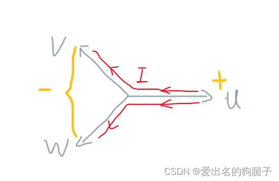
电角度0°位置确认: 准备一个直流电源,首先将电流调到一个远小于额定电流的值,按照U+ V- W- 给电机通以额定电压,之后慢慢增大电流,随着电流的增大,产生的磁场将增大,知道生成的磁场将电机吸附到一个特定的角度,同时也无法转动电机时,这个角度即为电机的0°电角度
3.2.1 机械角度计算
电机内部绝对位置磁传感器MT6701将电机的实时机械角度通过PWM输出,采用定时器输入捕获,计算PWM的占空比,换算得到电机的机械角度
需要注意的是,MT6701输出的计算占空比的时候需要增加对Start Pattern和End Pattern的处理
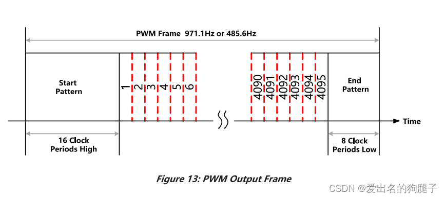
由于此处未将PWM的反馈接入定时器的Channel0 ,而是接入的Channel3 ,因此不能使用定时器的PWM输入功能,只能通过边沿触发来触发中断,对占空比和周期进行计算。
此方案的缺点是:计算出来的角度容易存在波动,特别是当电机极对数比较大的时候,假定极对数为20,通过此方案采集到的占空比波动 0.1%,则机械角度波动 0.1% x 360 = 0.36°,电角度波动 0.36° x 20 = 7.2°
3.2.2 电角度计算
通过绝对位置磁传感器可以获得当前的机械角度,机械角度 x 电机极对数 = 电角度,此方法适用于刚上电,电机转速较慢或静止时对电角度的计算,当电机高速运转时,磁传感器的反馈速度太慢,不能满足对电角度的实时计算,因此在电机高速运转过程中此方法不适用,针对电机运转过程中的角度识别,我们往往采用编码器实现对电机角度的读取。
我们的电机反馈信号中包含相对位置编码器和绝对位置磁传感器,两者结合即可实现绝对位置反馈。
首先在机器上电静止时,通过绝对位置磁传感器,计算电机的机械角度,同时将机械角度换算为增量式编码器的偏移量,编码器的值加上此偏移即可得到相对机械角度0°的编码器的值,之后机械角度和电角度均可通过编码器值进行换算即可。
3.2.3 代码实现
在输入捕获定时器内完成PWM反馈占空比计算,脉冲长度计算
float get_motor_position_sensor_feedback_of_duty(void)
{
    float tmp = 0;
    tmp = (duty < 100.0f) ? duty : 0;
    return tmp;
}

uint32_t get_motor_position_sensor_feedback_of_cycle_width(void)
{
    return cycle_width;
}

void TIMER4_IRQHandler(void)
{
    timer_ic_parameter_struct timer_icinitpara = {0};
    float start_pattern  = 0.0f;
    float end_pattern  = 0.0f;

    if (SET == timer_interrupt_flag_get(TIMER4,TIMER_INT_UP)) {
        if (capture_period < 100)  /* 防止溢出 */
            capture_period ++;
        timer_interrupt_flag_clear(TIMER4,TIMER_INT_UP);
    }

    if (SET == timer_interrupt_flag_get(TIMER4,TIMER_INT_CH3)) {
        timer_interrupt_flag_clear(TIMER4,TIMER_INT_CH3);
        if (0 == capture_step) {          /* 捕获上升沿 */
            TIMER_CNT(TIMER4) = 0;
            capture_period = 0;

            timer_icinitpara.icpolarity  = TIMER_IC_POLARITY_FALLING;
            timer_icinitpara.icselection = TIMER_IC_SELECTION_DIRECTTI;
            timer_icinitpara.icprescaler = TIMER_IC_PSC_DIV1;
            timer_icinitpara.icfilter    = 0x0;
            timer_input_capture_config(TIMER4, TIMER_CH_3, &timer_icinitpara);

            capture_step = 1;
        } else if (1 == capture_step) {    /* 捕获下降沿 */
            pulse_width = (capture_period << 16) + TIMER_CH3CV(TIMER4) + 1;

            timer_icinitpara.icpolarity  = TIMER_IC_POLARITY_RISING;
            timer_icinitpara.icselection = TIMER_IC_SELECTION_DIRECTTI;
            timer_icinitpara.icprescaler = TIMER_IC_PSC_DIV1;
            timer_icinitpara.icfilter    = 0x0;
            timer_input_capture_config(TIMER4, TIMER_CH_3, &timer_icinitpara);

            capture_step = 2;
        } else if (2 == capture_step) {    /* 捕获上升沿 完成一个周期捕获 */
            cycle_width = (capture_period << 16) + TIMER_CH3CV(TIMER4) + 1;
            /* 去除脉冲头部16clock和尾部8clock,详见MT6816datasheet */
            start_pattern = cycle_width * 16 / 4119;
            end_pattern = start_pattern / 2;
            pulse_width = pulse_width - start_pattern;
            cycle_width = cycle_width - start_pattern - end_pattern;
            duty = pulse_width * 100.0f / cycle_width;

            timer_icinitpara.icpolarity  = TIMER_IC_POLARITY_RISING;
            timer_icinitpara.icselection = TIMER_IC_SELECTION_DIRECTTI;
            timer_icinitpara.icprescaler = TIMER_IC_PSC_DIV1;
            timer_icinitpara.icfilter    = 0x0;
            timer_input_capture_config(TIMER4, TIMER_CH_3, &timer_icinitpara);

            capture_step = 0;
        }
    }
}
通过增量式编码器计算电机的机械角度及电角度,以及电机的速度,其中angle_encoder_refresh在每次进行FOC运算前均需要调用一次,用以刷新编码器的值,之后再进行计算得到电角度和机械角度的值:
#include "./motor_angle/motor_angle.h"
#include <rtthread.h>
#include "./bsp_timer/bsp_timer.h"

#define DBG_TAG               "motor_angle"
#define DBG_LVL               DBG_LOG
#include <rtdbg.h>

#define ENCODER_PPL         (1024*4)    /* encoder pluse per lap */
#define MOTOR_POLE_PAIRS    19          /* 极对数 */

static uint32_t motor_encoder_value = 0;
static uint8_t encoder_vaild_flag = 0;
rt_timer_t encoder_timer = RT_NULL;

void set_motor_encoder_inital_value(uint32_t value)
{
    motor_encoder_value = value % ENCODER_PPL;
    clear_encoder_timer_cnt();

    encoder_vaild_flag = 1;
}

float get_motor_mech_angle(void)
{
    float mech_angle = 0.0f;
    mech_angle = (motor_encoder_value + 1) * 360.0f / 4096;
    return mech_angle;
}

uint16_t get_motor_elec_angle(void)
{
    float elec_angle = 0.0f;
    float mech_angle = 0.0f;

    mech_angle = (motor_encoder_value + 1) * 360.0f / 4096;
    elec_angle = ((uint16_t)((uint32_t)(mech_angle * MOTOR_POLE_PAIRS) % 360));

    return elec_angle;
}

void angle_encoder_refresh(void)
{
    static int16_t last_count = 0;
    int16_t count = 0;
    int16_t count_inc = 0;

    if (encoder_vaild_flag == 1) {
        count = get_encoder_timer_cnt();
        count_inc = count - last_count;
        last_count = count;
        motor_encoder_value += count_inc;
        motor_encoder_value %= ENCODER_PPL;
    }
}

/**
 * @brief 计算电机速度
 *
 * @param execution_time 执行时间, Unit:ms
 * @return float 电机速度值 rpm
 */
float calcu_motor_speed(uint16_t execution_time)
{
    static int16_t last_cnt = 0;
    int16_t now_cnt = 0;
    int16_t inc_cnt = 0;
    float speed = 0;

    if (encoder_vaild_flag == 1) {
        now_cnt = get_encoder_timer_cnt();
        inc_cnt = now_cnt - last_cnt;
        last_cnt = now_cnt;
    }

    /* speed:lap per second, 1000:ms->s 60:s->min*/
    speed = (float)inc_cnt* 60.0f * (1000.0f / execution_time) / ENCODER_PPL;

    return speed;
}
利用绝对位置磁编码器完成增量式编码器偏移值计算:
static void right_motor_power_on_single_cailbration(void)
{
    float duty_temp[10] = {0};
    float differ = 0;
    float position_sensor_duty = 0;
    uint32_t cycle_width_tmp = 0;

    set_motor_break(ON);
    rt_thread_mdelay(200);

    /* 判断读取磁传感器反馈的pwm是否正常 */
    while (cycle_width_tmp > 860 || cycle_width_tmp < 820) {
        rt_thread_mdelay(100);
        cycle_width_tmp = get_motor_position_sensor_feedback_of_cycle_width();
        //TODO: 错误超限报错
    }
    /* 滤波 */
    for (int i = 0; i < 10; i ++) {
        duty_temp[i] = get_motor_position_sensor_feedback_of_duty();
        differ = duty_temp[i] - duty_temp[0];
        if (differ > 1 || differ < -1) {
            i = 0;
        }
        position_sensor_duty += duty_temp[i];
        rt_thread_mdelay(10);
    }
    position_sensor_duty /= 10;

    /* 设置电机编码器偏移 */
    set_motor_encoder_inital_value((uint32_t)(position_sensor_duty * 4096.0f / 100.0f));

    set_motor_break(OFF);
    set_motor_pwm_output(OFF);
}
3.3 角度识别初步验证
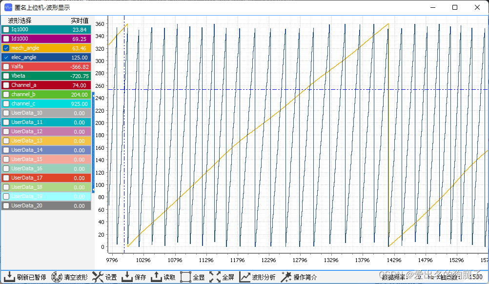
上述,我们已经实现了对电机电角度和机械角度的识别,那么到底对不对呢?因此我们需要对其进行验证,这里我们通过通过匿名上位机,将我们的机械角度和电角度显示出来,然后用手滚动电机,对我们的角度识别功能进行验证。
以下是顺时针转动电机时的机械角度和电角度的波形:
3.4 电流采集
FOC依赖于电机的相电流反馈,因此首先第一步便是完成电机相电流的采集,而针对不同的硬件设计,电流采集点设置不一样,对应的采样也存在区别,电流采样点一般存在以下三种情况:
- 在上桥臂采样
- 在下桥臂采样
- 在相线上采样
以上三种方式中,在相线上采样最为简单方便,由于FOC控制是三三导通,也就是任意时刻,电机驱动电路的六个MOS中总会有三个导通,这会导致在电机的三相上总会有电流流过,因此如果采用相线上进行电流采样,无需考虑采样点,需要什么时候采。
在上桥臂和在下桥臂此类采样方式原理相似,实际产品设计中下桥臂采样居多,原因就是成本要便宜,相对相线采样会要麻烦点,已七步控制为例,如下图:

1代表上桥臂打开,下桥臂关闭;0代表上桥臂关闭,下桥臂打开;如果采用的是下桥臂采样,当ABC=(110)时,电流流向如下图所示:
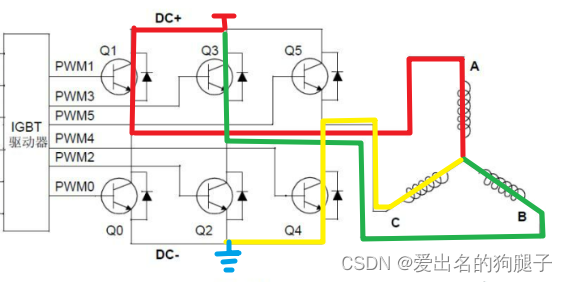
此时只有一个下桥臂打开,此时只能采集到1相的电流,另外两相采集到的电流为0,因此会导致采样不准确;因此针对这种情况需要严格控制采样时间,可以在第一步位置采样,此时下桥臂完全打开,此时采集到的电流三相均为准确的电流;当然有的为了节约硬件成本,下桥臂采样也分为单电阻、双电阻、三电阻采样,关于单电阻、双电阻、三电阻采样更多可以阅读:FOC 电流采样方案对比(单电阻/双电阻/三电阻)
由于本文所采用的硬件电流采样方案为相电流采集方案,因此软件设计上会简单很多,但依旧有几个需要注意的点。在进入PWM输出定时器更新中断后,首先第一步就是触发ADC的电流采样,此电路中,在电机三相上中的两相上均电流采样电路,通过配置ADC为注入并行的同步模式,ADC0和ADC1分别同时采集U相和V相的电流,注意此处的电流采集务必配置adc工作在同步模式下,采用并行方式,控制ADC采集到的时同一时刻下的U相和V相的电流,否则采集到的电流将不精准,之后根据基尔霍夫电流定律,流入节点的电流等于流出节点的电流,可以计算出W相的电流 Iw = 0 - Iu -Iv。(后文中U V W三相对应A B C三相,Iw Iu Iv 对应 Ia Ib Ic)
相电流采集作为FOC运算的输入,采样的准确性将将严重影响电机的实际运行效果,同时硬件设计上纹波的大小会影响实际控制中对于电机空载低速时的运动控制效果,由于电机在空载低速时,电机的相电流比较小,纹波误差过大,将导致控制误差大,影响电机的运行性能。
3.5 Clark和Park变化
clark变化也就是将静止的 a-b-c 三相坐标系转化为静止的 α-β 两相直角坐标系。
- Iα = Ia
- Iβ = (Ia + 2Ib) / sqrt(3)
Park变化就是将静止的α-β 两相直角坐标系转化为运动的 d-q 坐标系。
- Id = Iα · cosθ + Iβ · sinθ
- Iq = Iα · sinθ + Iβ · cosθ
两者均直接带入公式即可,具体的理论推导可以阅读直流无刷电机FOC控制算法 理论到实践 —— 理论(二)
经过Clark变化和Park变化之后即可得到 Id 和 Iq 的反馈电流,且 Id 和 Iq 理论上应为常量,此时便方便进行电流环的PID运算了。
3.5.1 代码实现
相电流采集及clark变换和park变换部分代码:
void motor_run_control(void)
{
    float cossitar = 0.0f;
    float sinsitart = 0.0f;

    start_adc_conversion();

    /* 计算电角度 */
    angle_encoder_refresh();
    motor_ctrl.elec_angle = get_motor_elec_angle();

//    测试公式使用
//    motor_ctrl.elec_angle ++;
//    motor_ctrl.elec_angle %= 360;
    if (count == 10) {
        motor_ctrl.ctrl_feedback.speed = calcu_motor_speed(1);

        speed_loop_pid_cal(&motor_ctrl);
    }

    /* 计算反馈电流Ia Ib Ic */
    motor_ctrl.ctrl_feedback.Ia = 1000 * get_u_current();
    motor_ctrl.ctrl_feedback.Ib = 1000 * get_v_current();
    motor_ctrl.ctrl_feedback.Ic = 0.0f - motor_ctrl.ctrl_feedback.Ia - motor_ctrl.ctrl_feedback.Ib;

    /* Clack变化 注意变化时需要增加系数2/3 */
    motor_ctrl.ctrl_feedback.Ialfa = motor_ctrl.ctrl_feedback.Ia;
    motor_ctrl.ctrl_feedback.Ibeta = SQRT3_INV * (2 * motor_ctrl.ctrl_feedback.Ib + motor_ctrl.ctrl_feedback.Ia);

    sinsitart = sintable[motor_ctrl.elec_angle];
    cossitar = sintable[(motor_ctrl.elec_angle + 90) % 360];
    /* Park变化 */
    motor_ctrl.ctrl_feedback.Id = motor_ctrl.ctrl_feedback.Ialfa * cossitar +
                                        motor_ctrl.ctrl_feedback.Ibeta * sinsitart;
    motor_ctrl.ctrl_feedback.Iq = -motor_ctrl.ctrl_feedback.Ialfa * sinsitart +
                                        motor_ctrl.ctrl_feedback.Ibeta * cossitar;
}
3.6 电流环PID计算
经过Clark变换和Park变换之后,转换到 q-d 坐标系,此时 Iq 和 Id 理论上为常量,可以开始进行PID计算了,这里采用位置式PID进行计算,电流环PID有几个关键参数,分别是 Iq_target、Id_target 和 out_limit。
-
Iq_target的取值不应过小也不应过大- 过小无法驱动电机,所以应大于电机启动电流
- 过大在空载情况下无法到达,甚至带载也无法到达,那此值肯定不合理
-
Id_target应取值为0 -
out_limit的取值应与PWM配置的ARR值有关,实际应取为ARR x (sqrt(3)) / 2,为什么要乘以sqrt3 / 2内,这是为了对电机的控制力是均匀的,也就是在将合成矢量力控制在六边形的内切圆内
3.6.1 代码实现
电流环代码实现如下:
#include "./current_loop/current_loop.h"
#include <rtthread.h>

#define SQRT3           (1.73205081f)

typedef struct pid_param_struct {
    float kp;
    float ki;
    float kd;
} pid_param_t;

typedef struct ek_struct {
    float ek;
    float ek_prev;
    float ek_last;
    float ek_sum;
    float ek_sum_limit;
    float out_limit;
} ek_t;

static pid_param_t q_axis_pid_param = {
    .kp = 0.1f,
    .ki = 0.05f,
    .kd = 0.0f,
//    .kp = 0.20f,
//    .ki = 0.03f,
//    .kd = 0.0f,
};

static pid_param_t d_axis_pid_param = {
    .kp = 0.04f,
    .ki = 0.015f,
    .kd = 0.0f,
};

static ek_t Iq_ek = {
    .ek = 0.0f,
    .ek_prev = 0.0f,
    .ek_last = 0,
    .ek_sum = 0.0f,
    .ek_sum_limit = 20000.0f,
    .out_limit = 1000.0f * SQRT3 / 2,
};

static ek_t Id_ek = {
    .ek = 0.0f,
    .ek_prev = 0.0f,
    .ek_last = 0,
    .ek_sum = 0.0f,
    .ek_sum_limit = 20000.0f,
    .out_limit = 1000.0f * SQRT3 / 2,
};

void set_current_loop_pid_p_param(float value)
{
    d_axis_pid_param.kp = value;
}

void set_current_loop_pid_i_param(float value)
{
    d_axis_pid_param.ki = value;
}

void set_current_loop_pid_d_param(float value)
{
    d_axis_pid_param.kd = value;
}

float get_current_loop_pid_p_param(void)
{
    return d_axis_pid_param.kp;
}

float get_current_loop_pid_i_param(void)
{
    return d_axis_pid_param.ki;
}

float get_current_loop_pid_d_param(void)
{
    return d_axis_pid_param.kd;
}

float p = 0;
float i = 0;

/* 位置式pid Vk = Kp * Ek + Ki * ∑Ek + Kd * (Ek - Ek-1) */
void current_loop_pid_cal(motor_control_t *p_motor_ctrl)
{
    float pid_out = 0.0f;
    uint8_t integral_satur_flag = 0;    //积分饱和标志位

    /*********************** Iq pid计算 ***********************/
    Iq_ek.ek = p_motor_ctrl->ctrl_target.Iq_target - p_motor_ctrl->ctrl_feedback.Iq;
    /* 抗饱和积分 */
    Iq_ek.ek_sum += Iq_ek.ek;
    if (Iq_ek.ek_sum > Iq_ek.ek_sum_limit) {
        Iq_ek.ek_sum -= Iq_ek.ek;
        integral_satur_flag = 1;
    }
    else if (Iq_ek.ek_sum < -Iq_ek.ek_sum_limit) {
        Iq_ek.ek_sum -= Iq_ek.ek;
        integral_satur_flag = 1;
    }

    /* 位置式PID计算 */
    pid_out = q_axis_pid_param.kp * Iq_ek.ek +
              q_axis_pid_param.ki * Iq_ek.ek_sum +
              q_axis_pid_param.kd * (Iq_ek.ek - Iq_ek.ek_last);
    Iq_ek.ek_last = Iq_ek.ek;

    if (pid_out > Iq_ek.out_limit) {
        pid_out = Iq_ek.out_limit;
        if (Iq_ek.ek > 0 && integral_satur_flag != 1)
            Iq_ek.ek_sum -= Iq_ek.ek;
    } else if (pid_out < -Iq_ek.out_limit) {
        pid_out = -Iq_ek.out_limit;
        if (Iq_ek.ek < 0 && integral_satur_flag != 1)
            Iq_ek.ek_sum -= Iq_ek.ek;
    }

    p_motor_ctrl->u_output.Vq = pid_out;

    integral_satur_flag = 0;
    /*********************** Id pid计算 ***********************/
    Id_ek.ek = p_motor_ctrl->ctrl_target.Id_target - p_motor_ctrl->ctrl_feedback.Id;
    /* 抗饱和积分 */
    Id_ek.ek_sum += Id_ek.ek;
    if (Id_ek.ek_sum > Id_ek.ek_sum_limit) {
        Id_ek.ek_sum -= Id_ek.ek;
        integral_satur_flag = 1;
    }
    else if (Id_ek.ek_sum < -Id_ek.ek_sum_limit) {
        Id_ek.ek_sum -= Id_ek.ek;
        integral_satur_flag = 1;
    }

    /* pid 计算 */
    p = q_axis_pid_param.kp * Iq_ek.ek;
    i = q_axis_pid_param.ki * Iq_ek.ek_sum;
    pid_out = d_axis_pid_param.kp * Id_ek.ek +
              d_axis_pid_param.ki * Id_ek.ek_sum +
              d_axis_pid_param.kd * (Id_ek.ek - Id_ek.ek_last);
    Id_ek.ek_last = Id_ek.ek;

    if (pid_out > Id_ek.out_limit) {
        pid_out = Id_ek.out_limit;
        if (Id_ek.ek > 0 && integral_satur_flag != 1)
            Id_ek.ek_sum -= Id_ek.ek;
    } else if (pid_out < -Id_ek.out_limit) {
        pid_out = -Id_ek.out_limit;
        if (Id_ek.ek < 0 && integral_satur_flag != 1)
            Id_ek.ek_sum -= Id_ek.ek;
    }

    p_motor_ctrl->u_output.Vd = pid_out;
}
3.7 反Park变化及SVPWM
经过电流环PID计算之后,得到 Vq 和 Vd ,接下来便是首先进行反Park变化,之后进行SVPWM计算,也是带入公式进行计算即可,相关理论部分可以查看 直流无刷电机FOC控制算法 理论到实践 —— 理论(二)
3.7.1 代码实现
void motor_run_control(void)
{
    float cossitar = 0.0f;
    float sinsitart = 0.0f;

    start_adc_conversion();

    /* 计算电角度 */
    angle_encoder_refresh();
    motor_ctrl.elec_angle = get_motor_elec_angle();

//    测试公式使用
//    motor_ctrl.elec_angle ++;
//    motor_ctrl.elec_angle %= 360;

//    while (adc_wait_conversion());
    /* 计算反馈电流Ia Ib Ic */
    motor_ctrl.ctrl_feedback.Ia = 1000 * get_u_current();
    motor_ctrl.ctrl_feedback.Ib = 1000 * get_v_current();
    motor_ctrl.ctrl_feedback.Ic = 0.0f - motor_ctrl.ctrl_feedback.Ia - motor_ctrl.ctrl_feedback.Ib;

    /* Clack变化 注意变化时需要增加系数2/3 */
    motor_ctrl.ctrl_feedback.Ialfa = motor_ctrl.ctrl_feedback.Ia;
    motor_ctrl.ctrl_feedback.Ibeta = SQRT3_INV * (2 * motor_ctrl.ctrl_feedback.Ib + motor_ctrl.ctrl_feedback.Ia);

    sinsitart = sintable[motor_ctrl.elec_angle];
    cossitar = sintable[(motor_ctrl.elec_angle + 90) % 360];
    /* Park变化 */
    motor_ctrl.ctrl_feedback.Id = motor_ctrl.ctrl_feedback.Ialfa * cossitar +
                                        motor_ctrl.ctrl_feedback.Ibeta * sinsitart;
    motor_ctrl.ctrl_feedback.Iq = -motor_ctrl.ctrl_feedback.Ialfa * sinsitart +
                                        motor_ctrl.ctrl_feedback.Ibeta * cossitar;

//    motor_ctrl.ctrl_target.Iq_target = 200.0f;
    motor_ctrl.ctrl_target.Id_target = 0;

    /* 电流环pid计算 */
    current_loop_pid_cal(&motor_ctrl);

//    motor_ctrl.u_output.Vq = 1000.0f * SQRT3 / 2;
//    motor_ctrl.u_output.Vq = 0.0f;
//    motor_ctrl.u_output.Vd = 0.0f;

    /* 反Park变化 */
    motor_ctrl.u_output.Valfa = -motor_ctrl.u_output.Vq * sinsitart +
                                       motor_ctrl.u_output.Vd * cossitar;
    motor_ctrl.u_output.Vbeta = motor_ctrl.u_output.Vq * cossitar +
                                       motor_ctrl.u_output.Vd * sinsitart;
    svpwm_calcu(&motor_ctrl);
    pwm_output_update(&motor_ctrl);
}

static void svpwm_calcu(motor_control_t *p_motor_ctrl)
{
    float u1 = 0.0f, u2 = 0.0f, u3 = 0.0f;
    float tmp = 0;
    uint8_t n = 0, sector = 0;

    float x = 0.0f, y = 0.0f, z = 0.0f;
    float t1 = 0.0f, t2 = 0.0f, ts = 0.0f;
    float ta = 0.0f, tb = 0.0f, tc = 0.0f;

    /* Step1: 判断扇区位置 */
    u1 = p_motor_ctrl->u_output.Vbeta;
    u2 = 0.5f * (-p_motor_ctrl->u_output.Vbeta + SQRT3 * p_motor_ctrl->u_output.Valfa);
    u3 = 0.5f * (-p_motor_ctrl->u_output.Vbeta - SQRT3 * p_motor_ctrl->u_output.Valfa);

    /* N = 4A + 2B + C (ABC不可能同时为1或0)*/
    /**********************************************************************
    (A,B,C)     000     001     010     011     100     101     110     111
    扇区        无       4       6       5       2       3       1      无
    N=4C+2B+1A   0       4       2       6       1       5       3       7
    N=4A+2B+1C   0       1       2       3       4       5       6       7
    **********************************************************************/
    n = 0;
    if (u1 > 0)
        n += 4;
    if (u2 > 0)
        n += 2;
    if (u3 > 0)
        n += 1;
    switch (n) {
        case 0: sector = 0; break;
        case 1: sector = 4; break;
        case 2: sector = 6; break;
        case 3: sector = 5; break;
        case 4: sector = 2; break;
        case 5: sector = 3; break;
        case 6: sector = 1; break;
        case 7: sector = 0; break;
        default: break;
    }

    /* Step2: 计算矢量作用时间 */
    x = (p_motor_ctrl->u_output.Vbeta);
    y = (SQRT3 / 2 * p_motor_ctrl->u_output.Valfa - 0.5f * p_motor_ctrl->u_output.Vbeta);
    z = (SQRT3 / 2 * p_motor_ctrl->u_output.Valfa + 0.5f * p_motor_ctrl->u_output.Vbeta);
    switch (sector) {
        case 0:
            t1 = 0;
            t2 = 0;
            break;
        case 1:
            t1 = y;
            t2 = x;
            break;
        case 2:
            t1 = -y;
            t2 = z;
            break;
        case 3:
            t1 = x;
            t2 = -z;
            break;
        case 4:
            t1 = -x;
            t2 = -y;
            break;
        case 5:
            t1 = -z;
            t2 = y;
            break;
        case 6:
            t1 = z;
            t2 = -x;
            break;
        case 7:
            //TODO:
            break;
        default:
            break;
    }

    ts = 1000.0f;
    if ((t1 + t2) > ts) {
        tmp = t1 + t2;
        t1 = ts * t1 / tmp;
        t2 = ts * t2 / tmp;
    }

    switch (sector) {
        case 0:
            ta = 0.5f * ts;
            tb = 0.5f * ts;
            tc = 0.5f * ts;
            break;
        case 1:
            tc = 0.5f * (ts - t1 - t2);
            tb = tc + t2;
            ta = tb + t1;
            break;
        case 2:
            tc = 0.5f * (ts - t1 - t2);
            ta = t2 + tc;
            tb = t1 + ta;
            break;
        case 3:
            ta = 0.5f * (ts - t1 - t2);
            tc = ta + t2;
            tb = tc + t1;
            break;
        case 4:
            ta = 0.5f * (ts - t1 - t2);
            tb = t2 + ta;
            tc = tb + t1;
            break;
        case 5:
            tb = 0.5f * (ts - t1 - t2);
            ta = tb + t2;
            tc = ta + t1;
            break;
        case 6:
            tb = 0.5f * (ts - t1 - t2);
            tc = tb + t2;
            ta = tc + t1;
            break;
        case 7:
            ta = 0;
            tb = 0;
            tc = 0;
            break;
        default:
            break;
    }
    p_motor_ctrl->u_output.channel_a = (int)ta;
    p_motor_ctrl->u_output.channel_b = (int)tb;
    p_motor_ctrl->u_output.channel_c = (int)tc;
}


static void pwm_output_update(motor_control_t *p_motor_ctrl)
{
    set_motor_pwm_duty(0, p_motor_ctrl->u_output.channel_a);
    set_motor_pwm_duty(1, p_motor_ctrl->u_output.channel_b);
    set_motor_pwm_duty(2, p_motor_ctrl->u_output.channel_c);
}
3.8 反Park变化及SVPWM算法验证
在进行完整的FOC运算之前,我们需要尽可能的将每个模块进行拆解验证,这样方便问题的定位,在2.3章节我们已经完成了对角度识别的初步,除此之外,我们还可以单独对反Park变化及SVPWM运算进行验证。
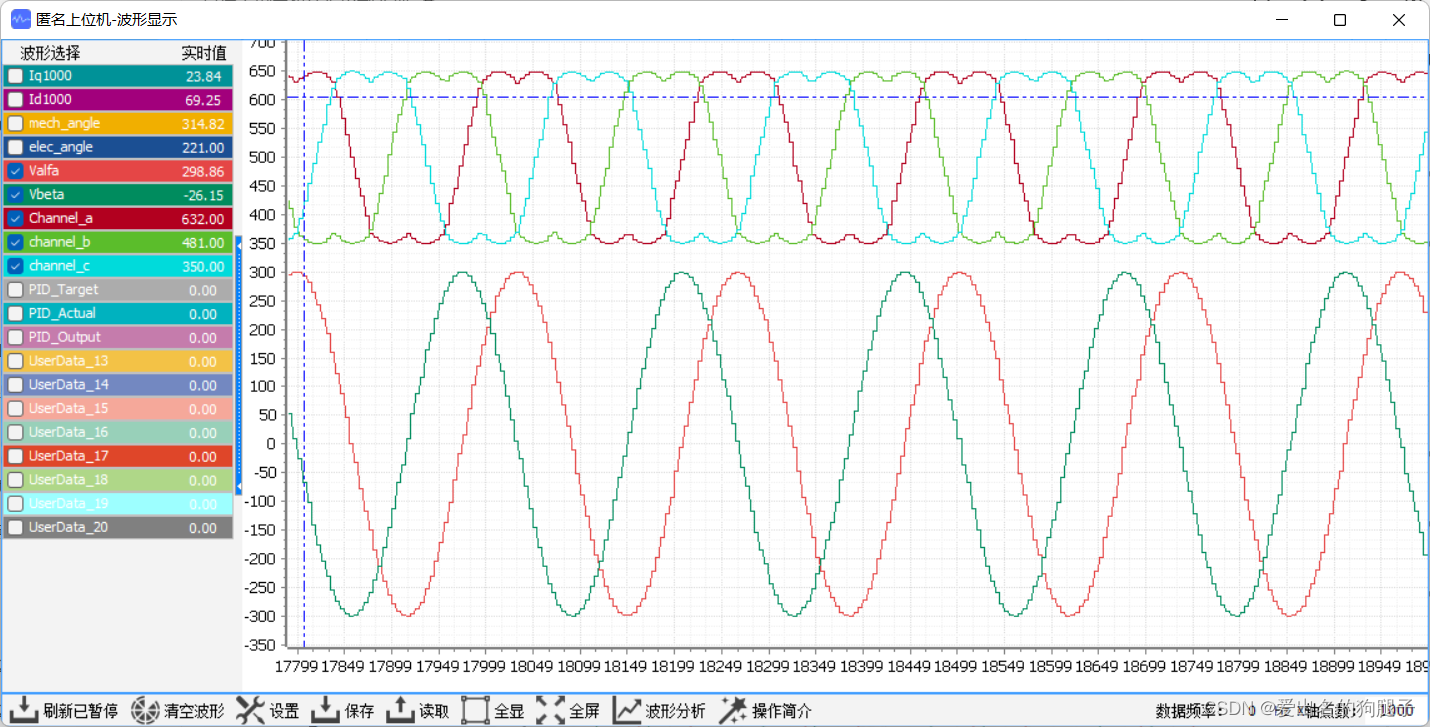
我们可以采用开环的方式实现反Park变换及SVPWM算法的验证,即在程序中将 Vq 和 Vd 强制赋值,之后进行反Park变化及SVPWM运算,分别查看反Park变化的输出以及SVPWM运算的输出。经过反Park变化之后,输出的 Vα 和 Vβ 是两个正弦波,经过SVPWM预算之后输出的channel_a、channel_b、channel_c为马鞍波
3.8.1 代码实现
将 3.7 章节中void motor_run_control(void)函数内下列代码取消注释
    motor_ctrl.u_output.Vq = 300.0f;
    motor_ctrl.u_output.Vd = 0.0f;
之后将motor_ctrl.u_output.Valfa motor_ctrl.u_output.Vbeta motor_ctrl.u_output.channel_a motor_ctrl.u_output.channel_b motor_ctrl.u_output.channel_c分别采用上位机进行输出显示,如下图所示:
3.9 角度识别深度验证
在 3.3 章节我们已经完成了对角度的初步确认,3.3 章节方法对电角度的方向、大小等大体做一个测试,但是对于误差无法进行测试,在2.8章节的基础上,针对角度误差我们可以通过SVPWM进行确认。
测试方法很简单,给SVPWM输入正负的Vq,Vd=0,计算电机正反转对应的速度,如果电角度计算误差很小,那么当输入为大小相等,方向相反的Vq时,电机正反转的速度应该误差非常小,如果偏大,则说明电角度存在一定误差,需要进行优化
3.10 电流环PID调节
以上便是FOC实现的全过程了,剩下的只需要调节电流环PID值至一个比较合适的值即可完成foc驱动直流无刷电机了,在调节电流环PID时,建议配合上位机,将参数采用波形的方式显示之后对参数进行调试,继续分享几个调试过程中的经验:
- 对于目标电流 Iq_target 的取值,我们可以首先采用开环看下电机空载时的电流运行最大值,之后将Iq_target 设置在此最大值之下
- 关闭PWM输出使能,也即关闭半桥驱动电路,查看采集到的 Ia Ib Ic ,以及经过运算之后的 Iq Id,理论上此时没有电流,应为0,但是实际中往往此值可能不为0,此误差越大,电机低速控制性能也就越差
- 电流环调节时,还需要结合实际电机的使用场景,简单的PID可能带载和空载效果不能同时满足,因此会要有一定的偏重,调参的时候可以加上与实际场景相近的负载或者采用多套PID参数的方式解决。
4. 速度环PID实现
实现电机的恒速运行,需要实现速度环PID,外环采用速度环,内环采用电流环,速度环的输出作为电流环的输入,因此速度环的输出为Iq_target,此外外环的计算速度应小于内环,因此速度环计算速度应小于电流环,本程序中,电流环计算周期为10k,速度环计算周期为1k
void motor_run_control(void)
{
    static uint8_t count = 0;
    float cossitar = 0.0f;
    float sinsitart = 0.0f;

    (count < 10) ? (count ++) : (count = 0);

    start_adc_conversion();

    /* 计算电角度 */
    angle_encoder_refresh();
    motor_ctrl.elec_angle = get_motor_elec_angle();

//    测试公式使用
//    motor_ctrl.elec_angle ++;
//    motor_ctrl.elec_angle %= 360;
    if (count == 10) {
        motor_ctrl.ctrl_feedback.speed = calcu_motor_speed(1);

        speed_loop_pid_cal(&motor_ctrl);
    }

//    while (adc_wait_conversion());
    /* 计算反馈电流Ia Ib Ic */
    motor_ctrl.ctrl_feedback.Ia = 1000 * get_u_current();
    motor_ctrl.ctrl_feedback.Ib = 1000 * get_v_current();
    motor_ctrl.ctrl_feedback.Ic = 0.0f - motor_ctrl.ctrl_feedback.Ia - motor_ctrl.ctrl_feedback.Ib;

    /* Clack变化 注意变化时需要增加系数2/3 */
    motor_ctrl.ctrl_feedback.Ialfa = motor_ctrl.ctrl_feedback.Ia;
    motor_ctrl.ctrl_feedback.Ibeta = SQRT3_INV * (2 * motor_ctrl.ctrl_feedback.Ib + motor_ctrl.ctrl_feedback.Ia);

    sinsitart = sintable[motor_ctrl.elec_angle];
    cossitar = sintable[(motor_ctrl.elec_angle + 90) % 360];
    /* Park变化 */
    motor_ctrl.ctrl_feedback.Id = motor_ctrl.ctrl_feedback.Ialfa * cossitar +
                                        motor_ctrl.ctrl_feedback.Ibeta * sinsitart;
    motor_ctrl.ctrl_feedback.Iq = -motor_ctrl.ctrl_feedback.Ialfa * sinsitart +
                                        motor_ctrl.ctrl_feedback.Ibeta * cossitar;

//    motor_ctrl.ctrl_target.Iq_target = 200.0f;
    motor_ctrl.ctrl_target.Id_target = 0;

    /* 电流环pid计算 */
    current_loop_pid_cal(&motor_ctrl);

//    motor_ctrl.u_output.Vq = 1000.0f * SQRT3 / 2;
//    motor_ctrl.u_output.Vq = 300.0f;
//    motor_ctrl.u_output.Vd = 0.0f;

    /* 反Park变化 */
    motor_ctrl.u_output.Valfa = -motor_ctrl.u_output.Vq * sinsitart +
                                       motor_ctrl.u_output.Vd * cossitar;
    motor_ctrl.u_output.Vbeta = motor_ctrl.u_output.Vq * cossitar +
                                       motor_ctrl.u_output.Vd * sinsitart;

    svpwm_calcu(&motor_ctrl);
#if 0
    set_motor_pwm_output(1);
#endif
    pwm_output_update(&motor_ctrl);
}
5. 结束语
以上便是FOC控制算法的全部实现,当然这也仅是直流无刷电机控制的开始,关于电机的控制还有很多,比如梯形加减速、S型曲线加减速算法,无感控制等等,这些都是可以深入学习的,今后我也将不断学习,同时不定期记录并发布相关的知识分享,一是用来巩固总结,二是记录自己踩过的坑,帮助需要的人,开源共创!
创作不易,转发请注明出处,点赞收藏+关注,找我不迷路!


