# show how to use FFT, filtered DC signal and return back to SampleValue-time zone.
# the basic concept is coming from ChatGPT.
# Write in python language.
#
# created by twicave.
# Jun09,2023
#
import numpy as np
import matplotlib.pyplot as plt

# 定义正弦信号
# 产生一个包含1000Hz、2000Hz两个正弦波信号和一个直流分量的复合信号
Fs = 20000;
f1 = 1000;
f2 = 2000;
t = np.arange(0, 0.01, 1/Fs);
signal = np.sin(2*np.pi*f1*t) + 0.7*np.sin(2*np.pi*f2*t) + 800;
np.savetxt('signal_data.txt', signal, fmt='%f', delimiter=',');

fig = plt.figure(1, figsize=(8, 10));
plt1 = fig.add_subplot(2, 1, 1)
plt1.plot(t,signal)
plt1.set_xlabel('Time (s)')
plt1.set_ylabel('Amplitude')
plt1.set_title('Original Signal')


# 下面,将对应信号转至频域消除0点后转回时域
x = signal

# 傅里叶变换
X = np.fft.fft(x)  # 计算原始信号的傅里叶变换

# 去除直流分量
X[0] = 0;

# 幅角变换
phase_shift = np.zeros(len(X))
phase_shift[len(X)//2] = -np.angle(X[len(X)//2])
X_corrected = X * np.exp(1j * phase_shift)

# 转回时域
x_withoutDC = np.real(np.fft.ifft(X_corrected));

print(x_withoutDC);
s_corrected = x_withoutDC;

plt2 = fig.add_subplot(2, 1, 2)
plt2.plot(t, s_corrected.real)
plt2.set_xlabel('Time (s)')
plt2.set_ylabel('Amplitude')
plt2.set_title('After filtered the DC of signal')

fig.suptitle("Demo program : filter DC of signal");
fig.show()
注意在频域去除直流信号后,需要对频谱中谱线的幅角做整体位移。你可以尝试把那段幅角变换的代码去除,看看时域信号会变成什么样子。
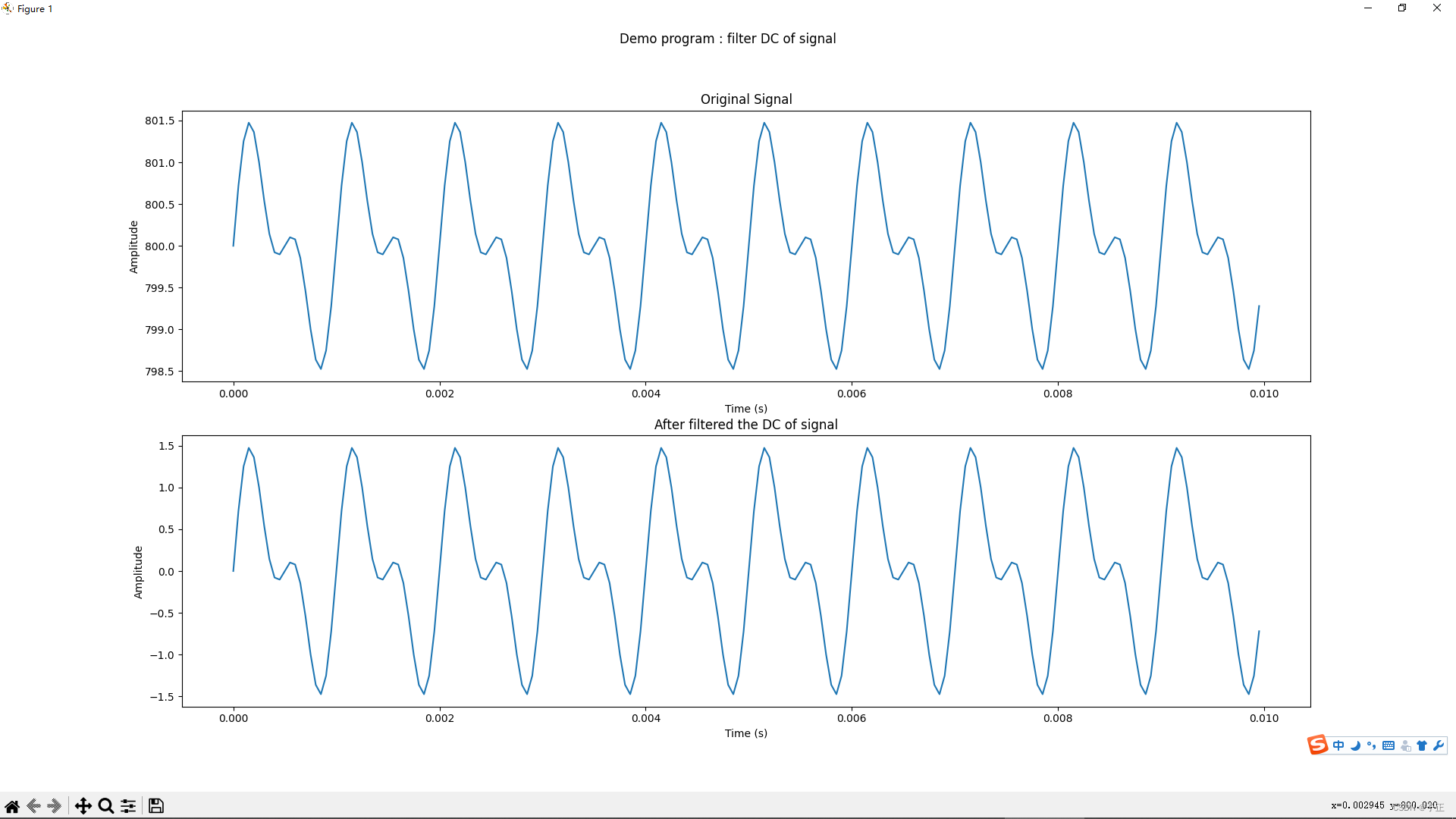
上面的代码可以直接在python环境中运行,运行结果:









![心法利器[85] | 算法技术和职业规划](https://img-blog.csdnimg.cn/img_convert/cd78741286a5cbfdea5da9305fecce39.png)

