目录
1.CubeMX生成工程文件
2.点灯1——轮询
3.点灯2——中断
3.1CubeMX配置时钟
3.2中断和事件简介
3.3配置GPIO口
3.4使能中断
3.5配置工程
3.6中断函数编写
1.CubeMX生成工程文件
1.1新建工程

1.2输入STM32C8T6选择芯片

1.3双击芯片

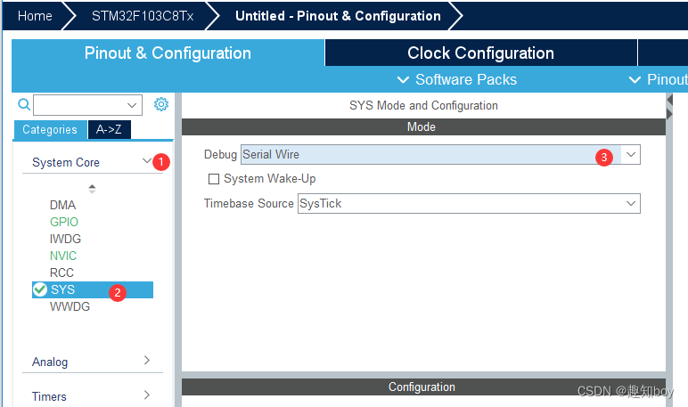
1.4 选择System Core—SYS——Debug设置为Serial Wire
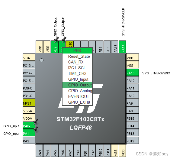
1.4点击引脚PA0、PA1设置为IO输入
PB8、PB9设置为输出引脚
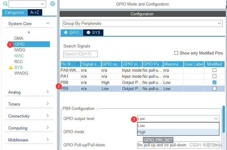
1.5设置IO口的默认电平
将PB8、PB9的电平设置为默认高电平,不亮灯
1.6项目输出设置
注意:文件路径不能有中文-图中3路径是错误的案例。

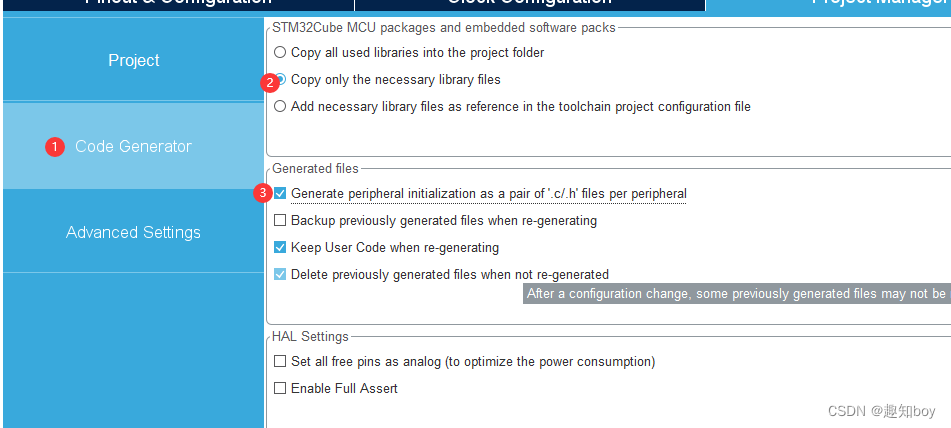
1.7代码生成设置
1.8生成代码

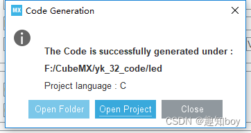
1.9成功生成代码-打开代码
2.点灯1——轮询
1.User/Core下有main函数

2.在gpio口函数中可以看到如何对IO口进行操作
F12进入对应的函数段。
主函数F12 ——MX_GPIO_Init();——进入gpio相关函数
gpio函数F12——HAL_GPIO_Init——进入HAL-gpio函数相关操作
编写主函数:
这里都喜欢宏定义,不喜直接用数字
/* USER CODE BEGIN Header */
/**
  ******************************************************************************
  * @file           : main.c
  * @brief          : Main program body
  ******************************************************************************
  * @attention
  *
  * Copyright (c) 2023 STMicroelectronics.
  * All rights reserved.
  *
  * This software is licensed under terms that can be found in the LICENSE file
  * in the root directory of this software component.
  * If no LICENSE file comes with this software, it is provided AS-IS.
  *
  ******************************************************************************
  */
/* USER CODE END Header */
/* Includes ------------------------------------------------------------------*/
#include "main.h"
#include "gpio.h"

/* Private includes ----------------------------------------------------------*/
/* USER CODE BEGIN Includes */

/* USER CODE END Includes */

/* Private typedef -----------------------------------------------------------*/
/* USER CODE BEGIN PTD */

/* USER CODE END PTD */

/* Private define ------------------------------------------------------------*/
/* USER CODE BEGIN PD */
#define Key_on 0
#define Key_off 1
/* USER CODE END PD */

/* Private macro -------------------------------------------------------------*/
/* USER CODE BEGIN PM */

/* USER CODE END PM */

/* Private variables ---------------------------------------------------------*/

/* USER CODE BEGIN PV */

/* USER CODE END PV */

/* Private function prototypes -----------------------------------------------*/
void SystemClock_Config(void);
/* USER CODE BEGIN PFP */

/* USER CODE END PFP */

/* Private user code ---------------------------------------------------------*/
/* USER CODE BEGIN 0 */
uint8_t Key_state(GPIO_TypeDef *GPIOx, uint16_t GPIO_Pin)
{
	if(HAL_GPIO_ReadPin(GPIOx, GPIO_Pin)== GPIO_PIN_RESET){
	//按键被按下
		while(HAL_GPIO_ReadPin(GPIOx, GPIO_Pin)==0);  //被按下时一直停在这里
		return Key_on;
	}else{
		return Key_off;
	}
}
/* USER CODE END 0 */

/**
  * @brief  The application entry point.
  * @retval int
  */
int main(void)
{
  /* USER CODE BEGIN 1 */

  /* USER CODE END 1 */

  /* MCU Configuration--------------------------------------------------------*/

  /* Reset of all peripherals, Initializes the Flash interface and the Systick. */
  HAL_Init();

  /* USER CODE BEGIN Init */

  /* USER CODE END Init */

  /* Configure the system clock */
  SystemClock_Config();

  /* USER CODE BEGIN SysInit */

  /* USER CODE END SysInit */

  /* Initialize all configured peripherals */
  MX_GPIO_Init();
  /* USER CODE BEGIN 2 */

  /* USER CODE END 2 */

  /* Infinite loop */
  /* USER CODE BEGIN WHILE */
  while (1)
  {
    /* USER CODE END WHILE */
		//HAL_GPIO_WritePin(GPIOB, GPIO_PIN_8|GPIO_PIN_9, GPIO_PIN_RESET);
		if(Key_state(GPIOA, GPIO_PIN_0)==Key_on){
			//按键被按下
			HAL_GPIO_TogglePin(GPIOB, GPIO_PIN_8);
		}
		if(Key_state(GPIOA, GPIO_PIN_1)==Key_on){
			//按键被按下
			HAL_GPIO_TogglePin(GPIOB, GPIO_PIN_9);
		}
    /* USER CODE BEGIN 3 */
  }
  /* USER CODE END 3 */
}

/**
  * @brief System Clock Configuration
  * @retval None
  */
void SystemClock_Config(void)
{
  RCC_OscInitTypeDef RCC_OscInitStruct = {0};
  RCC_ClkInitTypeDef RCC_ClkInitStruct = {0};

  /** Initializes the RCC Oscillators according to the specified parameters
  * in the RCC_OscInitTypeDef structure.
  */
  RCC_OscInitStruct.OscillatorType = RCC_OSCILLATORTYPE_HSI;
  RCC_OscInitStruct.HSIState = RCC_HSI_ON;
  RCC_OscInitStruct.HSICalibrationValue = RCC_HSICALIBRATION_DEFAULT;
  RCC_OscInitStruct.PLL.PLLState = RCC_PLL_NONE;
  if (HAL_RCC_OscConfig(&RCC_OscInitStruct) != HAL_OK)
  {
    Error_Handler();
  }

  /** Initializes the CPU, AHB and APB buses clocks
  */
  RCC_ClkInitStruct.ClockType = RCC_CLOCKTYPE_HCLK|RCC_CLOCKTYPE_SYSCLK
                              |RCC_CLOCKTYPE_PCLK1|RCC_CLOCKTYPE_PCLK2;
  RCC_ClkInitStruct.SYSCLKSource = RCC_SYSCLKSOURCE_HSI;
  RCC_ClkInitStruct.AHBCLKDivider = RCC_SYSCLK_DIV1;
  RCC_ClkInitStruct.APB1CLKDivider = RCC_HCLK_DIV1;
  RCC_ClkInitStruct.APB2CLKDivider = RCC_HCLK_DIV1;

  if (HAL_RCC_ClockConfig(&RCC_ClkInitStruct, FLASH_LATENCY_0) != HAL_OK)
  {
    Error_Handler();
  }
}

/* USER CODE BEGIN 4 */

/* USER CODE END 4 */

/**
  * @brief  This function is executed in case of error occurrence.
  * @retval None
  */
void Error_Handler(void)
{
  /* USER CODE BEGIN Error_Handler_Debug */
  /* User can add his own implementation to report the HAL error return state */
  __disable_irq();
  while (1)
  {
  }
  /* USER CODE END Error_Handler_Debug */
}

#ifdef  USE_FULL_ASSERT
/**
  * @brief  Reports the name of the source file and the source line number
  *         where the assert_param error has occurred.
  * @param  file: pointer to the source file name
  * @param  line: assert_param error line source number
  * @retval None
  */
void assert_failed(uint8_t *file, uint32_t line)
{
  /* USER CODE BEGIN 6 */
  /* User can add his own implementation to report the file name and line number,
     ex: printf("Wrong parameters value: file %s on line %d\r\n", file, line) */
  /* USER CODE END 6 */
}
#endif /* USE_FULL_ASSERT */
3.点灯2——中断
- 配置时钟
- 配置GPIO口
- 使能中断
- 配置工程
3.1CubeMX配置时钟
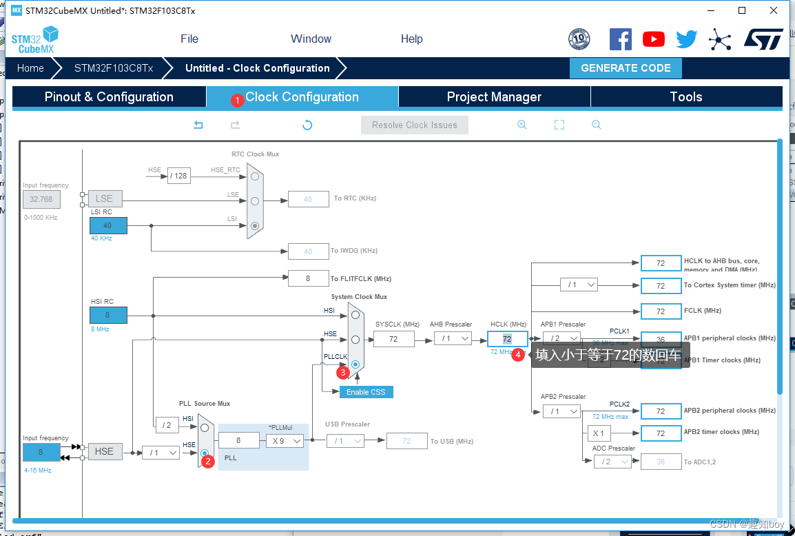
作用:改变芯片的运行频率,频率高功耗大,速度快。
1.首先新建项目-找到芯片
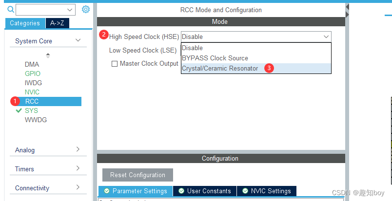
SYS设置为Serial Wire
RCC中的High Speed Clock设置为Crystal/Ceramic Resonator
2.设置Clock Configration
3.2中断和事件简介
中断优先级中的级别
- 抢占优先级:高抢占可以打断低抢占
- 响应优先级:高响应不可以打断低响应
中断是软件级别的事
事件是硬件级别的事
EXTI初始化结构体:
typedef struct
{
//中断/事件线
uint32_t EXTI_Line; /*!< Specifies the EXTI lines to be enabled or
disabled.
This parameter can be any combination value
of @ref EXTI_Lines */
//EXTI 模式
EXTIMode_TypeDef EXTI_Mode; /*!< Specifies the mode for the EXTI lines.
This parameter can be a value of @ref
EXTIMode_TypeDef */
//触发类型
EXTITrigger_TypeDef EXTI_Trigger; /*!< Specifies the trigger signal active edge for
the EXTI lines.
This parameter can be a value of @ref
EXTITrigger_TypeDef */
//EXTI 控制
FunctionalState EXTI_LineCmd; /*!< Specifies the new state of the selected EXTI
lines.
This parameter can be set either to ENABLE or
DISABLE */
}EXTI_InitTypeDef;
中断/事件线:
#define EXTI_Line0 ((uint32_t)0x00001) /*!< External interrupt line 0 */
#define EXTI_Line1 ((uint32_t)0x00002) /*!< External interrupt line 1 */
#define EXTI_Line2 ((uint32_t)0x00004) /*!< External interrupt line 2 */
#define EXTI_Line3 ((uint32_t)0x00008) /*!< External interrupt line 3 */
#define EXTI_Line4 ((uint32_t)0x00010) /*!< External interrupt line 4 */
#define EXTI_Line5 ((uint32_t)0x00020) /*!< External interrupt line 5 */
#define EXTI_Line6 ((uint32_t)0x00040) /*!< External interrupt line 6 */
#define EXTI_Line7 ((uint32_t)0x00080) /*!< External interrupt line 7 */
#define EXTI_Line8 ((uint32_t)0x00100) /*!< External interrupt line 8 */
#define EXTI_Line9 ((uint32_t)0x00200) /*!< External interrupt line 9 */
#define EXTI_Line10 ((uint32_t)0x00400) /*!< External interrupt line 10 */
#define EXTI_Line11 ((uint32_t)0x00800) /*!< External interrupt line 11 */
#define EXTI_Line12 ((uint32_t)0x01000) /*!< External interrupt line 12 */
#define EXTI_Line13 ((uint32_t)0x02000) /*!< External interrupt line 13 */
#define EXTI_Line14 ((uint32_t)0x04000) /*!< External interrupt line 14 */
#define EXTI_Line15 ((uint32_t)0x08000) /*!< External interrupt line 15 */
#define EXTI_Line16 ((uint32_t)0x10000) /*!< External interrupt line 16
Connected to the PVD Output */
#define EXTI_Line17 ((uint32_t)0x20000) /*!< External interrupt line 17
Connected to the RTC Alarm event */
#define EXTI_Line18 ((uint32_t)0x40000) /*!< External interrupt line 18
Connected to the USB OTG FS Wakeup from suspend event */
#define EXTI_Line19 ((uint32_t)0x80000) /*!< External interrupt line 19
Connected to the Ethernet Wakeup event */
#define EXTI_Line20 ((uint32_t)0x00100000) /*!< External interrupt line 20
Connected to the USB OTG HS (configured in FS) Wakeup event */
#define EXTI_Line21 ((uint32_t)0x00200000) /*!< External interrupt line 21
Connected to the RTC Tamper and Time Stamp events */
#define EXTI_Line22 ((uint32_t)0x00400000) /*!< External interrupt line 22
Connected to the RTC Wakeup event */
EXTI模式:
typedef enum
{
EXTI_Mode_Interrupt = 0x00, //产生中断
EXTI_Mode_Event = 0x04 //产生事件
}EXTIMode_TypeDef;
触发类型:
typedef enum
{
EXTI_Trigger_Rising = 0x08, //上升沿
EXTI_Trigger_Falling = 0x0C, //下降沿
EXTI_Trigger_Rising_Falling = 0x10 //上升沿和下降沿都触发
}EXTITrigger_TypeDef;
EXTI控制:
使能 EXTI ,一般都是使能, ENABLE
FunctionalState EXTI_LineCmd; 设置为ENABLE
中断优先级设置
STM32通过中断控制器NVIC(Nested Vectored Interrupt Controller)进行中断的管理 。
NVIC是属于Cortex内核的器件,不可屏蔽中断(NMI)和外部中断都由它来处理,但是SYSTICK
不是由NVIC控制的。
typedef struct
{
uint8_t NVIC_IRQChannel;
uint8_t NVIC_IRQChannelPreemptionPriority; //抢断优先级
uint8_t NVIC_IRQChannelSubPriority; //响应优先级
FunctionalState NVIC_IRQChannelCmd;
} NVIC_InitTypeDef;
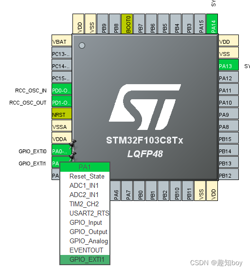
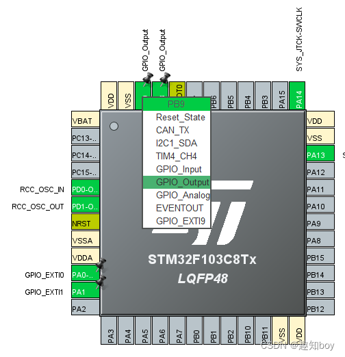
3.3配置GPIO口
SYS、RCC和之前一样的设置
PA0和PA1设置为外部中断
PB8、PB9设置为输出端口

3.4使能中断
NVIC中使能中断打开

3.5配置工程
Project和Code Generator 和以前一样的设置
记得Toolchain/IDE也要改为MDK-ARM,图中是错误示范

然后Generate Code然后打开
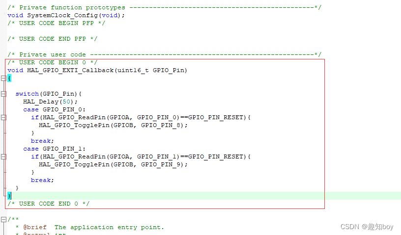
3.6中断函数编写
void HAL_GPIO_EXTI_Callback(uint16_t GPIO_Pin)
{

	switch(GPIO_Pin){
		HAL_Delay(50);
		case GPIO_PIN_0:
			if(HAL_GPIO_ReadPin(GPIOA, GPIO_PIN_0)==GPIO_PIN_RESET){
				HAL_GPIO_TogglePin(GPIOB, GPIO_PIN_8);
			}
			break;
		case GPIO_PIN_1:
			if(HAL_GPIO_ReadPin(GPIOA, GPIO_PIN_1)==GPIO_PIN_RESET){
				HAL_GPIO_TogglePin(GPIOB, GPIO_PIN_9);
			}
			break;
	}
}
在main.c——USER CODE BEGAIN中编写中断函数。
