本篇文档分为两部分:
第一部分是添加 UART 控制台(实现打印):用来向控制台对接的终端输出打印信息;该部分只需要实现两个函数,串口初始化和系统输出函数,即可完成 UART 控制台打印功能。
第二部分是移植 FinSH 组件(实现命令输入),用以在控制台输入命令调试系统;该部分的实现基于第一部分,只需要添加 FinSH 组件源码并再对接一个系统输入函数即可实现。
1. 在 Nano 上添加 UART 控制台(实现打印)
1)代码
使用串口1作为控制台输出串口
方法一:默认使用宏 INIT_BOARD_EXPORT() 进行自动初始化,不需要显式调用,如下所示。
方法二:可以使用显式调用:uart_init() 需要在 board.c 中的 rt_hw_board_init() 函数中调用。
//main.c 实现串口初始化、rt_hw_console_output
#include "gd32f3x0.h"
#include "gd32f330c_start.h"
#include "systick.h"
#include <rtthread.h>

#define delay_ms(x)   rt_thread_mdelay(x)

/*!
    \brief      configure the USART0 GPIO ports
    \param[in]  none
    \param[out] none
    \retval     none
*/
void usart1_gpio_config(void)
{
    /* enable COM GPIO clock */
    rcu_periph_clock_enable(RCU_GPIOA);

    /* connect port to USARTx_Tx */
    gpio_af_set(GPIOA, GPIO_AF_4, GPIO_PIN_8);

    /* connect port to USARTx_Rx */
    gpio_af_set(GPIOA, GPIO_AF_1, GPIO_PIN_15);

    /* configure USART Tx as alternate function push-pull */
    gpio_mode_set(GPIOA, GPIO_MODE_AF, GPIO_PUPD_PULLUP, GPIO_PIN_8);
    gpio_output_options_set(GPIOA, GPIO_OTYPE_PP, GPIO_OSPEED_10MHZ, GPIO_PIN_8);

    /* configure USART Rx as alternate function push-pull */
    gpio_mode_set(GPIOA, GPIO_MODE_AF, GPIO_PUPD_PULLUP, GPIO_PIN_15);
    gpio_output_options_set(GPIOA, GPIO_OTYPE_PP, GPIO_OSPEED_10MHZ, GPIO_PIN_15);
}

/*!
    \brief      configure the USART0
    \param[in]  none
    \param[out] none
    \retval     none
*/
void usart1_config(void)
{
    /* enable USART clock */
    rcu_periph_clock_enable(RCU_USART1);

    /* USART configure */
    usart_deinit(USART1);
    usart_word_length_set(USART1, USART_WL_8BIT);
    usart_stop_bit_set(USART1, USART_STB_1BIT);
    usart_parity_config(USART1, USART_PM_NONE);
    usart_baudrate_set(USART1, 115200U);
    usart_receive_config(USART1, USART_RECEIVE_ENABLE);
    usart_transmit_config(USART1, USART_TRANSMIT_ENABLE);

    usart_enable(USART1);
}

void uart1_init(void)
{
  usart1_gpio_config();
  usart1_config();
}

void rt_hw_console_output(const char *str)
{
    rt_size_t i = 0, size = 0;
    char a = '\r';

    size = rt_strlen(str);
    for (i = 0; i < size; i++)
    {
        if (*(str + i) == '\n')
        {
            usart_data_transmit(USART1, a);
          while(RESET == usart_flag_get(USART1,USART_FLAG_TBE));
        }
        usart_data_transmit(USART1, *(str + i));
          while(RESET == usart_flag_get(USART1,USART_FLAG_TBE));
    }

}


/*!
    \brief      main function
    \param[in]  none
    \param[out] none
    \retval     none
*/

int main(void)
{

    /* enable the LED GPIO clock */
    rcu_periph_clock_enable(RCU_GPIOB);
    /* configure led GPIO port */
    gpio_mode_set(GPIOB, GPIO_MODE_OUTPUT, GPIO_PUPD_NONE, GPIO_PIN_1);
    gpio_output_options_set(GPIOB, GPIO_OTYPE_PP, GPIO_OSPEED_50MHZ, GPIO_PIN_1);

    gpio_bit_set(GPIOB, GPIO_PIN_1);

    while(1){
        /* turn on led1 */
        gpio_bit_write(GPIOB, GPIO_PIN_1, RESET);
        rt_kprintf("Hello\n");
        delay_ms(1000);

        /* turn off led1 */
        gpio_bit_write(GPIOB, GPIO_PIN_1, SET);
        delay_ms(1000);
    }
}
Note
注:注意:RT-Thread 系统中已有的打印均以 \n 结尾,而并非 \r\n,所以在字符输出时,需要在输出 \n 之前输出 \r,完成回车与换行,否则系统打印出来的信息将只有换行。
//board.c 在 board.c 中的 rt_hw_board_init() 函数中调用
/*
 * Copyright (c) 2006-2019, RT-Thread Development Team
 *
 * SPDX-License-Identifier: Apache-2.0
 *
 * Change Logs:
 * Date           Author       Notes
 * 2017-07-24     Tanek        the first version
 * 2018-11-12     Ernest Chen  modify copyright
 */

#include <stdint.h>
#include <rthw.h>
#include <rtthread.h>

#define _SCB_BASE       (0xE000E010UL)
#define _SYSTICK_CTRL   (*(rt_uint32_t *)(_SCB_BASE + 0x0))
#define _SYSTICK_LOAD   (*(rt_uint32_t *)(_SCB_BASE + 0x4))
#define _SYSTICK_VAL    (*(rt_uint32_t *)(_SCB_BASE + 0x8))
#define _SYSTICK_CALIB  (*(rt_uint32_t *)(_SCB_BASE + 0xC))
#define _SYSTICK_PRI    (*(rt_uint8_t  *)(0xE000ED23UL))

void uart1_init(void);

// Updates the variable SystemCoreClock and must be called
// whenever the core clock is changed during program execution.
extern void SystemCoreClockUpdate(void);

// Holds the system core clock, which is the system clock
// frequency supplied to the SysTick timer and the processor
// core clock.
extern uint32_t SystemCoreClock;

static uint32_t _SysTick_Config(rt_uint32_t ticks)
{
    if ((ticks - 1) > 0xFFFFFF)
    {
        return 1;
    }

    _SYSTICK_LOAD = ticks - 1;
    _SYSTICK_PRI = 0xFF;
    _SYSTICK_VAL  = 0;
    _SYSTICK_CTRL = 0x07;

    return 0;
}

#if defined(RT_USING_USER_MAIN) && defined(RT_USING_HEAP)
#define RT_HEAP_SIZE 1024
static uint32_t rt_heap[RT_HEAP_SIZE];     // heap default size: 4K(1024 * 4)
RT_WEAK void *rt_heap_begin_get(void)
{
    return rt_heap;
}

RT_WEAK void *rt_heap_end_get(void)
{
    return rt_heap + RT_HEAP_SIZE;
}
#endif

/**
 * This function will initial your board.
 */
void rt_hw_board_init()
{
    /* System Clock Update */
    SystemCoreClockUpdate();

    /* System Tick Configuration */
    _SysTick_Config(SystemCoreClock / RT_TICK_PER_SECOND);

  	uart1_init();

    /* Call components board initial (use INIT_BOARD_EXPORT()) */
#ifdef RT_USING_COMPONENTS_INIT
    rt_components_board_init();
#endif

#if defined(RT_USING_USER_MAIN) && defined(RT_USING_HEAP)
    rt_system_heap_init(rt_heap_begin_get(), rt_heap_end_get());
#endif
}

void SysTick_Handler(void)
{
    /* enter interrupt */
    rt_interrupt_enter();

    rt_tick_increase();

    /* leave interrupt */
    rt_interrupt_leave();
}
2)编译

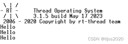
3) 运行
2. 在 Nano 上添加 FinSH 组件(实现命令输入)
RT-Thread FinSH 是 RT-Thread 的命令行组件(shell),提供一套供用户在命令行调用的操作接口,主要用于调试或查看系统信息。它可以使用串口 / 以太网 / USB 等与 PC 机进行通信,使用 FinSH 组件基本命令的效果图如下所示:
本文以串口 UART 作为 FinSH 的输入输出端口与 PC 进行通信,描述如何在 Nano 上实现 FinSH shell 功能。
在 RT-Thread Nano 上添加 FinSH 组件,实现 FinSH 功能的步骤主要如下:
添加 FinSH 源码到工程。
实现函数对接。
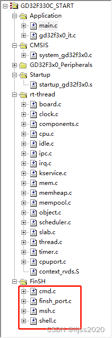
1)复制 FinSH 源码到目标裸机工程:直接复制 Nano 源码中 rtthread-nano/components 文件夹下的 finsh 文件夹到工程中
2)finsh_port.c
注释掉RT_WEAK char rt_hw_console_getchar(void)
#include <rthw.h>
#include <rtconfig.h>

#ifndef RT_USING_FINSH
#error Please uncomment the line <#include "finsh_config.h"> in the rtconfig.h
#endif

#ifdef RT_USING_FINSH

//RT_WEAK char rt_hw_console_getchar(void)
//{
//    /* Note: the initial value of ch must < 0 */
//    int ch = -1;

//#error "TODO 4: Read a char from the uart and assign it to 'ch'."

//    return ch;
//}

#endif /* RT_USING_FINSH */
3) rtconfig.h
增加 #define RT_USING_FINSH
4)main.c
#include "gd32f3x0.h"
#include "gd32f330c_start.h"
#include "systick.h"
#include <rtthread.h>

#define delay_ms(x)   rt_thread_mdelay(x)

/*!
    \brief      configure the USART0 GPIO ports
    \param[in]  none
    \param[out] none
    \retval     none
*/
void usart1_gpio_config(void)
{
    /* enable COM GPIO clock */
    rcu_periph_clock_enable(RCU_GPIOA);

    /* connect port to USARTx_Tx */
    gpio_af_set(GPIOA, GPIO_AF_4, GPIO_PIN_8);

    /* connect port to USARTx_Rx */
    gpio_af_set(GPIOA, GPIO_AF_1, GPIO_PIN_15);

    /* configure USART Tx as alternate function push-pull */
    gpio_mode_set(GPIOA, GPIO_MODE_AF, GPIO_PUPD_NONE, GPIO_PIN_8);
    gpio_output_options_set(GPIOA, GPIO_OTYPE_PP, GPIO_OSPEED_10MHZ, GPIO_PIN_8);

    /* configure USART Rx as alternate function push-pull */
    gpio_mode_set(GPIOA, GPIO_MODE_AF, GPIO_PUPD_NONE, GPIO_PIN_15);
    gpio_output_options_set(GPIOA, GPIO_OTYPE_PP, GPIO_OSPEED_10MHZ, GPIO_PIN_15);
}

/*!
    \brief      configure the USART0
    \param[in]  none
    \param[out] none
    \retval     none
*/
void usart1_config(void)
{
    /* enable USART clock */
    rcu_periph_clock_enable(RCU_USART1);

    /* USART configure */
    usart_deinit(USART1);
    usart_word_length_set(USART1, USART_WL_8BIT);
    usart_stop_bit_set(USART1, USART_STB_1BIT);
    usart_parity_config(USART1, USART_PM_NONE);
    usart_baudrate_set(USART1, 115200U);
    usart_receive_config(USART1, USART_RECEIVE_ENABLE);
    usart_transmit_config(USART1, USART_TRANSMIT_ENABLE);

    usart_enable(USART1);
}

void uart1_init(void)
{
  usart1_gpio_config();
  usart1_config();
}

void rt_hw_console_output(const char *str)
{
    rt_size_t i = 0, size = 0;
    char a = '\r';

    size = rt_strlen(str);
    for (i = 0; i < size; i++)
    {
        if (*(str + i) == '\n')
        {
            usart_data_transmit(USART1, a);
          while(RESET == usart_flag_get(USART1,USART_FLAG_TBE));
        }
        usart_data_transmit(USART1, *(str + i));
          while(RESET == usart_flag_get(USART1,USART_FLAG_TBE));
    }

}

char rt_hw_console_getchar(void)
{
    int ch = -1;

    if (usart_flag_get(USART1, USART_FLAG_RBNE) != RESET)
    {
        ch = usart_data_receive(USART1);
    }
    else
    {
        if(usart_flag_get(USART1, USART_FLAG_ORERR) != RESET)
        {
            usart_flag_clear(USART1,USART_FLAG_ORERR);
        }
        rt_thread_mdelay(10);
    }
    return ch;
}


/*!
    \brief      main function
    \param[in]  none
    \param[out] none
    \retval     none
*/

int main(void)
{

    /* enable the LED GPIO clock */
    rcu_periph_clock_enable(RCU_GPIOB);
    /* configure led GPIO port */
    gpio_mode_set(GPIOB, GPIO_MODE_OUTPUT, GPIO_PUPD_NONE, GPIO_PIN_1);
    gpio_output_options_set(GPIOB, GPIO_OTYPE_PP, GPIO_OSPEED_50MHZ, GPIO_PIN_1);

    gpio_bit_set(GPIOB, GPIO_PIN_1);

    while(1){
        /* turn on led1 */
        gpio_bit_write(GPIOB, GPIO_PIN_1, RESET);
//        rt_kprintf("Hello\n");
        delay_ms(1000);

        /* turn off led1 */
        gpio_bit_write(GPIOB, GPIO_PIN_1, SET);
        delay_ms(1000);
    }
}
5)finsh_config.h
屏蔽 #define FINSH_THREAD_PRIORITY 21
屏蔽 //#define FINSH_THREAD_STACK_SIZE 1024
/* FinSH config file */

#ifndef __MSH_CFG_H__
#define __MSH_CFG_H__

// <<< Use Configuration Wizard in Context Menu >>>
#define RT_USING_FINSH
#define FINSH_USING_MSH
#define FINSH_USING_MSH_ONLY
// <h>FinSH Configuration
// <o>the priority of finsh thread <1-30>
//  <i>the priority of finsh thread
//  <i>Default: 21
//#define FINSH_THREAD_PRIORITY       21
// <o>the stack of finsh thread <1-4096>
//  <i>the stack of finsh thread
//  <i>Default: 4096  (4096Byte)
//#define FINSH_THREAD_STACK_SIZE     1024

#define FINSH_USING_SYMTAB
// <c1>Enable command description
//  <i>Enable command description
#define FINSH_USING_DESCRIPTION
//  </c>
// </h>

// <<< end of configuration section >>>
#endif
6)编译

7) 在超级终端中使用FinSH
 \ | /
- RT -     Thread Operating System
 / | \     3.1.5 build May 17 2023
 2006 - 2020 Copyright by rt-thread team
msh >help
RT-Thread shell commands:
version          - show RT-Thread version information
list_thread      - list thread
list_sem         - list semaphore in system
list_mailbox     - list mail box in system
list_timer       - list timer in system
help             - RT-Thread shell help.
ps               - List threads in the system.

msh >ps
thread   pri  status      sp     stack size max used left tick  error
-------- ---  ------- ---------- ----------  ------  ---------- ---
tshell     6  ready   0x0000008c 0x00000200    98%   0x00000004 000
tidle      7  ready   0x00000040 0x00000080    50%   0x0000001e 000
main       2  suspend 0x00000080 0x00000100    96%   0x00000013 000
msh >


