文章目录
- 1.rgb、depth相机标定矫正
- 1.1.标定rgb相机
- 1.2.标定depth相机
- 1.3.rgb、depth相机一起标定(效果重复了,但是推荐使用)
- 1.4.取得标定结果
- 1.4.1.得到的标定结果的意义
- 1.5.IR、RGB相机分别应用标定结果
- 1.5.1.openCV应用标定结果
- 1.5.2.ros2工程应用标定结果
- 2.rgb、depth相机配准
- 2.1.求外参(R、T矩阵)
- 2.2.求两个相机之间的R、T矩阵
- 2.3.进行D2C操作
- 3.题外话
相机自带的D2C效果不好,颜色和点云没有很好地匹配上,自己按照下面的介绍手动匹配一下。
1.rgb、depth相机标定矫正
在下载来的sdk,里面没有标定的文件:ost.yaml.
需要自己进行标定、生成。
我所使用的相机型号是Astra_pro,它是一个单目结构光相机,有一个RGB摄像头+一个IR摄像头。实际上算是一个双目相机(rgb+ir)。【奥比中光Astra深度传感器工作原理】
在ros2(humble)中,需要先安装相机标定套件:
    sudo apt install ros-humble-camera-*
    sudo apt install ros-humble-launch-testing-ament-cmake
在我的系统中,可以分别对这两个进行相机进行标定

在标定时,具体的参数(相机、话题、格子数等等)要根据你实际的情况进行填写。
1.1.标定rgb相机
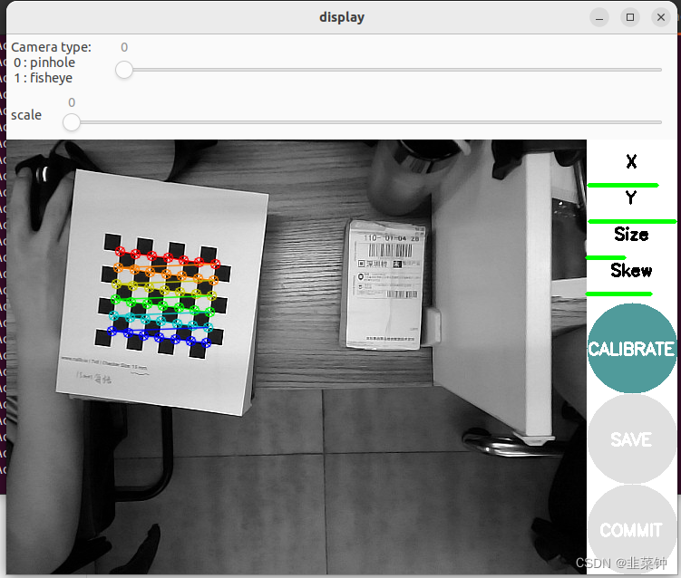
执行以下命令
ros2 run camera_calibration cameracalibrator --size 6x7 --square 0.015 --no-service-check image:=/camera/color/image_raw camera:=/camera/color
1.2.标定depth相机
深度摄像头看起来和RGB摄像头差别很大,实际上有很多相似之处。就Kinect而言,其通过一个红外散斑发射器发射红外光束,光束碰到障碍物后反射回深度摄像头,然后通过返回散斑之间的几何关系计算距离。其实,Kinect的深度摄像头就是一个装了滤波片的普通摄像头,只对红外光成像的摄像头(可以这么认为)。因此要对其标定,只需用红外光源照射物体即可,LED红外光源在淘宝上就20元一个。还有一点必须注意,在拍摄红外照片时,要用黑胶带(或其他东西)将Kinect的红外发射器完全挡住,否则其发出的散斑会在红外照片中产生很多亮点,不利于棋盘角点的检测。
————————————————
原文链接:https://blog.csdn.net/aichipmunk/article/details/9264703
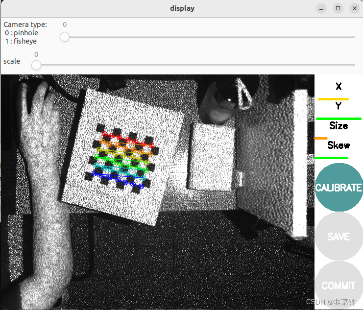
我这里就偷懒了,直接用自带的红外散斑发射器来标定。追求准确的同学,最好还是按照上面说的遮住红外发射器+买一个红外光源。
ros2 run camera_calibration cameracalibrator --size 6x7 --square 0.015 --no-service-check image:=/camera/ir/image_raw camera:=/camera/ir
1.3.rgb、depth相机一起标定(效果重复了,但是推荐使用)
假如已经进行了上面rgb、depth相机的分别标定,这一步其实没必要进行,效果是一样的。
但是这个一起标定的话,有个好处:在后面计算外参时,可以直接拿到同一时刻两个相机分别拍到的图像。
【ROS下采用camera_calibration进行双目相机标定】
ros2 run camera_calibration cameracalibrator --size 6x7 --square 0.015 --approximate 0.1 --no-service-check left:=/camera/ir/image_raw left_camera:=/camera/ir right:=/camera/color/image_raw right_camera:=/camera/color
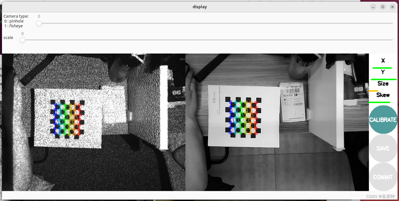
1.4.取得标定结果
参考上面提到的文章进行操作后,分别可以在/tmp目录下得到标定后的数据。
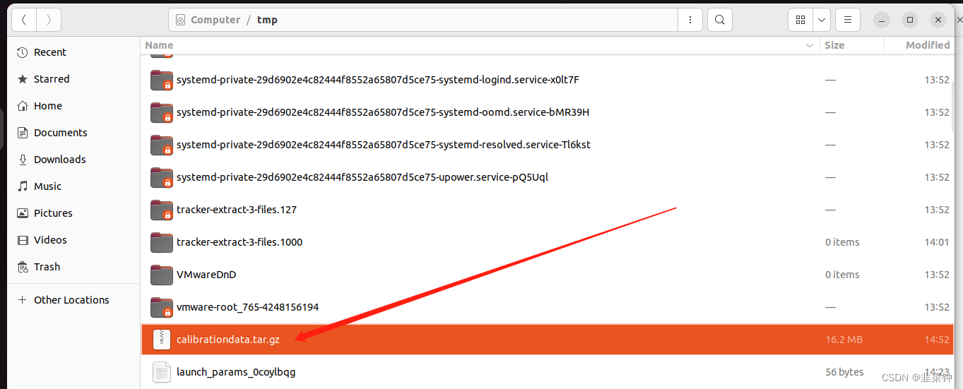 无论是用camera_calibration进行单目标定和双目标定,貌似没有本质的区别,都是分别得到两个相机的内参。
得到的相机内参入下图所示:
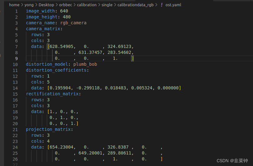
以上图为例,可以知道相机的内参fx=628.54905,fy=631.37457;这是说相机镜头的焦距为628.54905mm吗?
不是,这个是以像素为单位的,镜头的焦距为628.54905像素。那1像素代表多少mm呢(像元尺寸)?
这个要看相机感光芯片的尺寸及芯片的分辨率。假设感光芯片尺寸为WH(单位mm),分辨率为UV,那么像元尺寸为[W/U, H/V).
 以上面的海康威视相机为例,假如我标定时使用的是这个相机(像元尺寸6.9um),然后得到的内参为fx=628.54905,fy=631.37457,那么,通过标定得知的镜头焦距:f=628.54905 * 6.9 um=4336.988445um=4.3mm。也就是说这个镜头大概是4.3mm的镜头。
关于靶面、像元的介绍,可以看看这里:【相机和镜头选型需要注意哪些问题】、【相机靶面尺寸详解+工业相机选型】
1.4.1.得到的标定结果的意义
各标定参数的意义:
image_width、image_height代表图片的长宽
camera_name为摄像头名
camera_matrix规定了摄像头的内部参数矩阵
distortion_model指定了畸变模型
distortion_coefficients指定畸变模型的系数
rectification_matrix为矫正矩阵,一般为单位阵
projection_matrix为外部世界坐标到像平面的投影矩阵
也可以看看这个
【相机内参标定究竟标了什么?相机内参外参保姆级教程】
1.5.IR、RGB相机分别应用标定结果
得到标定结果后,有两种方法应用标定结果。
1.5.1.openCV应用标定结果
假如需要自己进行相机的画面矫正,可以使用opencv来进行。opencv只用到上面的camera_matrix、distortion_coefficients这两组数据
【opencv畸变校正的两种方法】
1.5.2.ros2工程应用标定结果
我这里可以直接修改卖家提供的源码里面的launch.xml文件的内容,让其加载标定结果。
设置好文件路径之后,出现 “Invalid camera calibration URL”的解决办法
要加上file://前缀,格式如下:
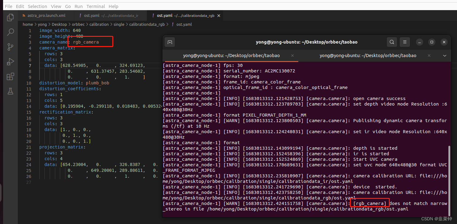
 假如出现 does not match narrow_stereo in时
 将ost.yaml里面相机的名字改成和报错的一致:
 由于AstraPro的rgb、ir镜头的畸变不明显,标定校准后,畸变的校准效果也不明显,这里就不贴对比图上来了。
2.rgb、depth相机配准
两个相机都标定完之后,就需要进行配准,也就是要得到从ir图到rgb图的映射(旋转矩阵R、平移矩阵T),从而得到对应深度点的颜色值。
【视觉SLAM十四讲(第二版)第5讲习题解答】
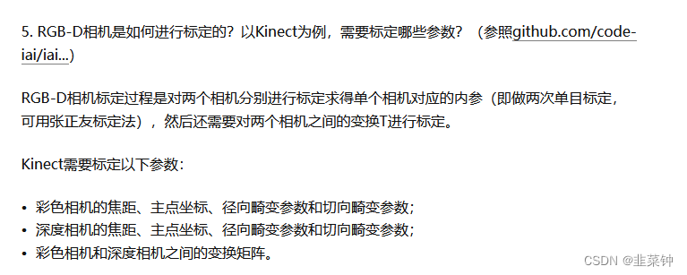
根据【Kinect深度图与RGB摄像头的标定与配准】里面分析到的,要求RT,就需要先求出外参。
2.1.求外参(R、T矩阵)
从【Opencv——相机标定】的介绍可以看到,opencv的函数calibrateCamera在根据若干组棋盘格点坐标,计算得到相机内参时,也可以得到每张图片的外参。但是我们目前是用ros的camera_calibration得到的相机内参(虽然内部也是opencv,但是camera_calibration没有给我们保存外参),所以不能够直接得到可用的外参。
但是,我们可以从前面双目标定得到的结果中选取同一时刻拍摄的两张图片(一张是rgb相机的,一张是ir相机的)
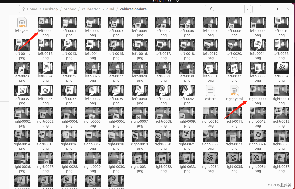 然后按照【OPENCV已知内参求外参】、【OPENCV标定外参】,利用上面的两张图片+各自相机的内参,分别算出每个相机的外参,主要代码如下:
#include <opencv2/opencv.hpp>
#include <opencv2/calib3d.hpp>

using namespace std;
using namespace cv;

// 根据已知的信息计算外参
int calcExtrinsics(string fileName, Mat cameraMatrix, Mat distCoeffs, Size board_size, double rectWidth,
                   Mat &R, Mat &T)
{
    vector<Point2f> image_points;  /* 图像上检测到的角点 */

    Mat imageInput = imread(fileName, IMREAD_COLOR);

    cout << "image size:" << imageInput.cols << "," << imageInput.rows << endl;

    cout << "cameraMatrix:" << cameraMatrix << endl;
    cout << "distCoeffs:"   << distCoeffs   << endl;

    // 显示一下纠正后的图像,直观地检查一下传递进来的cameraMatrix、disCoeffs有没有问题
    Mat undistortMat;
    undistort(imageInput, undistortMat, cameraMatrix, distCoeffs);
    imshow("undistort mat", undistortMat);
    cout << "undistortMat size:" << undistortMat.cols << "," << undistortMat.rows << endl;

    /* 提取角点 */
    if (0 == findChessboardCorners(imageInput, board_size, image_points))
    {
        cout << "can not find chessboard corners!\n"; //找不到角点
        return -1;
    }
    else
    {
        Mat view_gray;

        cvtColor(imageInput, view_gray, COLOR_RGB2GRAY);

        /* 亚像素精确化 */
        find4QuadCornerSubpix(view_gray, image_points, Size(11,11)); //对粗提取的角点进行精确化

        //        // 看看点的排列顺序
        //        image_points_buf[0] += Point2f(-50, -100);
        //        image_points_buf[8] += Point2f(-60, -100);

        /* 在图像上显示角点位置 */
        Mat displayImg = imageInput.clone();
        drawChessboardCorners(displayImg, board_size, image_points, true); //用于在图片中标记角点

        imshow("Camera Calibration", displayImg);//显示图片
    }

    // 上面已经得到了标定板的二维坐标,现在来填充三维坐标
    vector<Point3f> object_points;
    for(int i = 0; i < board_size.height; i++)
    {
        for(int j = 0; j < board_size.width; j++)
        {
            object_points.push_back(Point3f(rectWidth * j, rectWidth * i, 0));
        }
    }

    //    cout << "object points:" << object_points << endl;

    cout << image_points.size() << " "<< object_points.size() << endl;

    //创建旋转矩阵和平移矩阵
    //    Mat rvecs = Mat::zeros(3, 1, CV_64FC1);
    //    Mat tvecs = Mat::zeros(3, 1, CV_64FC1);
    Mat rvec;
    Mat tvec;

    //求解pnp
    bool pnpResult = false;
    //    pnpResult = solvePnP(object_points, image_points, cameraMatrix, distCoeffs, rvec, tvec);
    pnpResult = solvePnPRansac(object_points, image_points, cameraMatrix, distCoeffs, rvec, tvec);

    cout << "pnp result:" << pnpResult << endl;
    if(pnpResult == false)
    {
        return -2;
    }

    Mat rotM;
    Rodrigues(rvec, rotM);  //将旋转向量变换成旋转矩阵

    R = rotM;
    T = tvec;

    // 直观地检验一下计算到的R、T有没有问题
    {
        vector<Point2f> image_points2; /* 保存重新计算得到的投影点 */
        projectPoints(object_points, rvec, tvec, cameraMatrix, distCoeffs, image_points2);

        /* 在图像上显示角点位置 */
        Mat displayImg = imageInput.clone();
        drawChessboardCorners(displayImg, board_size, image_points2, true); //用于在图片中标记角点

        imshow("projectPoints image", displayImg);//显示图片
    }

    return 0;
}

// 分别对两个相机进行外参计算
void calcExtrinsicsDemo()
{
//#define calc_rgb // 通过注释这个来切换

    // 图像路径
    std::string fileName;

    Size board_size = Size(7, 6);   // 标定板上每行、列的角点数
    double rectWidth = 0.015;       // 标定版棋盘格的大小,单位m

    //相机内参矩阵
    Mat cameraMatrix;
    //相机畸变系数
    Mat distCoeffs;


#ifdef calc_rgb
    fileName = "/home/yong/Desktop/orbbec/calibration/dual/calibrationdata/right-0000.png";     // rgb 图像路径
#else
    fileName = "/home/yong/Desktop/orbbec/calibration/dual/calibrationdata/left-0000.png";     // ir 图像路径
#endif


#ifdef calc_rgb
    // rgb相机参数
    double camData[] = {
                        628.549051,  0.000000,   324.691230,
                        0.000000,    631.374570, 283.546017,
                        0.000000,    0.000000,   1.000000};
    cameraMatrix = Mat(3, 3, CV_64F, camData);


    double distData[] = {0.195904,
                         -0.299118,
                         0.018483,
                         0.005324,
                         0.000000};
    distCoeffs = Mat(5, 1, CV_64F, distData);
#else
    // ir相机参数
    double camData[] = {
                        588.560930, 0.000000  ,  306.212790,
                        0.000000  , 590.708852,  250.991143,
                        0.000000  , 0.000000  ,  1.000000};
    cameraMatrix = Mat(3, 3, CV_64F, camData);

    double distData[] = {-0.044573,
                         0.212463,
                         0.006501,
                         -0.006851,
                         0.000000};
    distCoeffs = Mat(5, 1, CV_64F, distData);
#endif

    Mat R,T;
    calcExtrinsics(fileName, cameraMatrix, distCoeffs, board_size, rectWidth, R, T);

    cout << "R:" << R << endl;
    cout << "T:" << T << endl;

}
2.2.求两个相机之间的R、T矩阵
通过上面的代码,计算得到了rgb、ir(depth)相机的外参:
    // rgb
//R:[0.9932208622695912, -0.104179968756072, -0.05156406561195055;
//     0.09876316392901367, 0.9902419675733234, -0.09831929163314773;
//     0.06130380251811834, 0.09256014134873089, 0.9938181242210883]
//        T:[-0.1985727556503669;
//                -0.1321870936778361;
//                0.5274038381890026]

    // ir
//R:[0.9949185009774844, -0.1001176653598934, 0.01065971367344506;
//     0.1005768682173857, 0.9931508653869539, -0.05946135014214975;
//     -0.004633572304179904, 0.06023131796689411, 0.9981736914704138]
//        T:[-0.1633382501071563;
//                -0.1003269691775472;
//                0.5162717136103199]
然后我们根据【Kinect深度图与RGB摄像头的标定与配准】里面的公式:
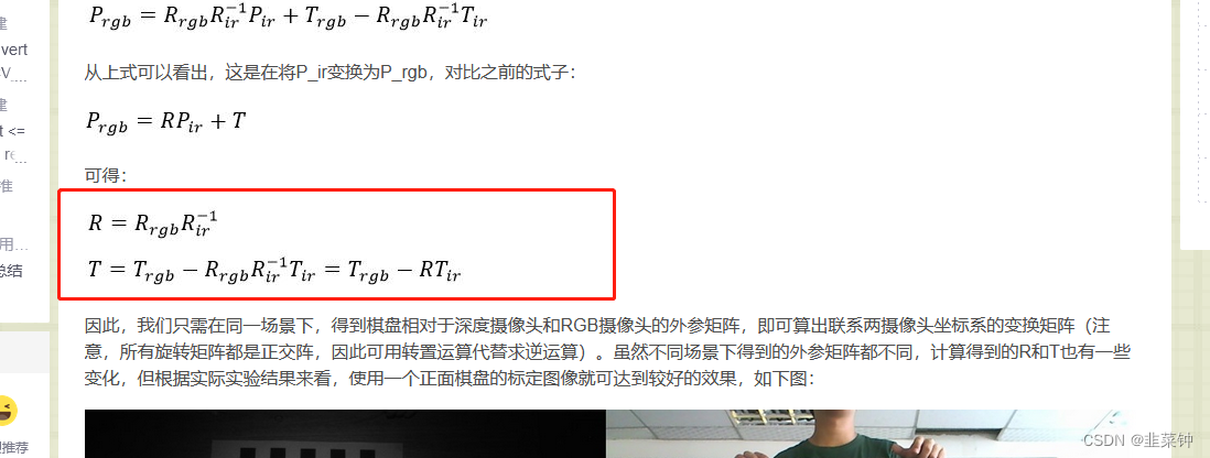 计算一下R、T:
Mat R_rgb, T_rgb, R_ir, T_ir;
    {
        double data[] =  {0.9932208622695912, -0.104179968756072, -0.05156406561195055,
                         0.09876316392901367, 0.9902419675733234, -0.09831929163314773,
                         0.06130380251811834, 0.09256014134873089, 0.9938181242210883};
        R_rgb = Mat(3, 3, CV_64F, data).clone();
    }
    {
        double data[] =  {-0.1985727556503669, -0.1321870936778361, 0.5274038381890026};
        T_rgb = Mat(3, 1, CV_64F, data).clone();
    }
    {
        double data[] =  {0.9949185009774844, -0.1001176653598934, 0.01065971367344506,
                         0.1005768682173857, 0.9931508653869539, -0.05946135014214975,
                         -0.004633572304179904, 0.06023131796689411, 0.9981736914704138};
        R_ir = Mat(3, 3, CV_64F, data).clone();
    }
    {
        double data[] =  {-0.1633382501071563,
                         -0.1003269691775472,
                         0.5162717136103199};
        T_ir = Mat(3, 1, CV_64F, data).clone();
    }

    //    cout << R_rgb << endl << T_rgb;


    Mat R, T;
    R = R_rgb * R_ir.inv();
    T = T_rgb - R*T_ir;

    cout << "R:" << R << endl;
    cout << "T:" << T << endl;

    /*
R:[0.9980544085026888, -0.0005053133907268852, -0.06234695122237745;
 -0.00192747042416588, 0.9992391545866735, -0.03895377772019822;
 0.06231919869600642, 0.03899816148599567, 0.9972940694071134]
T:[-0.003415024268825395;
 -0.01214055388563491;
 0.02662079621125524]
 */
2.3.进行D2C操作
有了R和T,我们就可以用rgb来对点云着色),注意,此时我们不是用ir图了,而是用depth图了,depth图是16uc1类型的,其数值表示深度(单位mm)。
#include <Eigen/Core>
#include <Eigen/LU>

void depthToColor(Mat depthMat, Mat bgrMat)
{
    Eigen::Matrix3f R_ir2rgb;
    R_ir2rgb <<
        0.9980544085026888, -0.0005053133907268852, -0.06234695122237745,
        -0.00192747042416588, 0.9992391545866735, -0.03895377772019822,
        0.06231919869600642, 0.03899816148599567, 0.9972940694071134;

    Eigen::Vector3f T_ir2rgb;
    T_ir2rgb <<
        -0.003415024268825395,
        -0.01214055388563491,
        0.02662079621125524;


    Eigen::Matrix3f K_ir;           // ir内参矩阵
    K_ir <<
        588.560930, 0.000000  ,  306.212790,
        0.000000  , 590.708852,  250.991143,
        0.000000  , 0.000000  ,  1.000000;

    Eigen::Matrix3f K_rgb;          // rgb内参矩阵
    K_rgb <<
        628.549051,  0.000000,   324.691230,
        0.000000,    631.374570, 283.546017,
        0.000000,    0.000000,   1.000000;

//    Eigen::Matrix3f R;
//    Eigen::Vector3f T;
//    R = K_rgb*parm->R_ir2rgb*K_ir.inverse();
//    T = K_rgb*parm->T_ir2rgb;

    cout << "K_rgb:\n" << K_rgb << endl;
    cout << "K_ir:\n" << K_ir << endl;
//    cout << "R:\n" << R << endl;
//    cout << "T:\n" << T << endl;

    // 4.2 计算投影
    Mat result(480, 640, CV_8UC3);
    int i = 0;
    for (int row = 0; row < 480; row++)
    {
        for (int col = 0; col < 640; col++)
        {
            unsigned short* p = (unsigned short*)depthMat.data;
            unsigned short depthValue = p[row * 640 + col];
            //cout << "depthValue       " << depthValue << endl;
            if (depthValue != std::numeric_limits<unsigned short>::infinity() &&
                depthValue != -std::numeric_limits<unsigned short>::infinity() &&
                depthValue != 0 &&
                depthValue != 65535)
            {
                // 投影到彩色图上的坐标

                // 1)构造一个三维向量p_ir = (x, y, z),其中x,y是该点的像素坐标,z是该像素的深度值;
                Eigen::Vector3f p_ir(col, row, 1.0f);

               // 2)用Kinect内参矩阵H_ir的逆,乘以p_ir得到对应的空间点坐标P_ir,具体公式见上文第四部分(配准);
                Eigen::Vector3f P_ir = K_ir.inverse() *  (p_ir *  (depthValue / 1000.f)); // (除以1000,是为了从毫米变米)
                // 现在这个P_ir,可以放到点云去显示

                // 3)由于P_ir是该点在Kinect坐标系下的坐标,我们需要将其转换到RGB摄像头的坐标系下,具体的,就是乘以一个旋转矩阵R,再加上一个平移向量T,得到P_rgb;
                Eigen::Vector3f P_rgb = R_ir2rgb * P_ir + T_ir2rgb;

                // 4)用RGB摄像头的内参矩阵H_rgb乘以P_rgb,得到p_rgb,
                // p_rgb也是一个三维向量,其x和y坐标即为该点在RGB图像中的像素坐标,取出该像素的颜色,作为深度图像中对应像素的颜色;
                Eigen::Vector3f p_rgb = K_rgb * P_rgb;

                int X = static_cast<int>(p_rgb [0] / p_rgb [2]);                // !!!Z_rgb*p_rgb -> p_rgb
                int Y = static_cast<int>(p_rgb [1] / p_rgb [2]);                // !!!Z_rgb*p_rgb -> p_rgb
                //cout << "X:       " << X << "     Y:      " << Y << endl;
                if ((X >= 0 && X < 640) && (Y >= 0 && Y < 480))
                {
                    //cout << "X:       " << X << "     Y:      " << Y << endl;
                    result.data[i * 3]     = bgrMat.data[3 * (Y * 640 + X)];
                    result.data[i * 3 + 1] = bgrMat.data[3 * (Y * 640 + X) + 1];
                    result.data[i * 3 + 2] = bgrMat.data[3 * (Y * 640 + X) + 2];
                }
                else
                {
                    result.data[i * 3] = 0;
                    result.data[i * 3 + 1] = 0;
                    result.data[i * 3 + 2] = 0;
                }
            }
            else
            {
                result.data[i * 3] = 0;
                result.data[i * 3 + 1] = 0;
                result.data[i * 3 + 2] = 0;
            }
            i++;
        }
    }

    imshow("result", result);
}
根据原文的介绍:
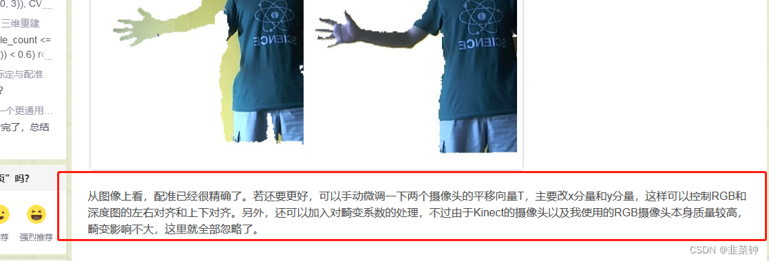
在应用R、T矩阵时,可以根据实际情况微调一下T矩阵的x、y
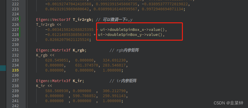
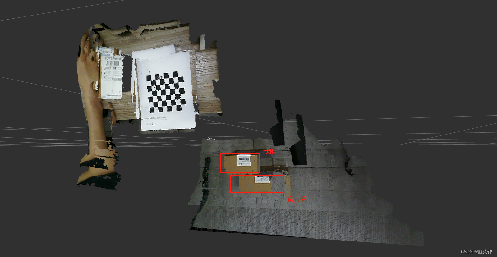
但是经过尝试,假如调好了近处的物体,远处的物体和颜色又对不齐;反之亦然。可能是硬件的问题。
另外,我用这种方式得到点云与官方的点云在X、Y方向有较大的偏差,可能是我通过标定得到的内参和官方的内参存在较大差异导致的。
3.题外话
由于我们用的点云来源自ir相机,所以手眼标定时,要用ir相机去参与标定,而不是rgb相机。
参考:
【1.Astra相机标定】
【【Nav2中文网】ROS2单目相机标定教程】
【深度图与彩色图的配准与对齐】
【Kinect深度图与RGB摄像头的标定与配准】
【RGBD相机实用问题】
【相机内参标定究竟标了什么?相机内参外参保姆级教程】



![[架构之路-187]-《软考-系统分析师》-5-数据库系统 - 操作型数据库OLTP与分析型数据库OLAP比较](https://img-blog.csdnimg.cn/img_convert/0bc6f03d7788b8326ff2d71a2f7aa492.png)
