前言:
在单片机中,将程序分为boot和app,这样可以实现一些功能:使用串口更新app等等;
需求:
编写boot和sys程序段,分别放在flash内存不同位置,先执行boot然后执行sys:boot使用串口发送“JUMP APP!!”,sys使用串口循环打印"GOOD DAY!!";
准备:
- IDE:IAR
- 硬件:stm32f103小蓝板
项目配置
一. 获得初始化代码
使用代码生成工具stm32cubeMX生成初始化代码,获得初始化项目boot:
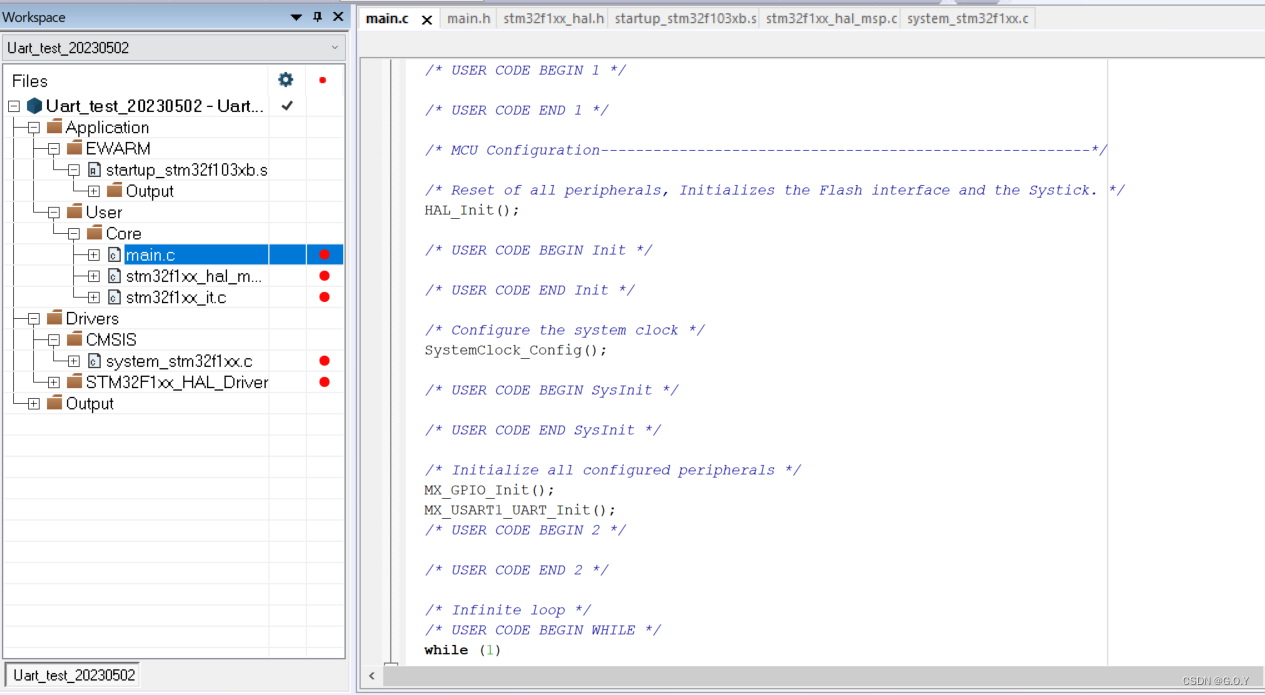 同理获得初始化项目:
二. 配置Boot项目
boot项目不需要进行额外配置,知需要编写跳转函数就可以了,跳转地址: 0x8003000:
#define APP_FLASH_ADDRESS (0x8003000)	// 根据需求设置app地址
typedef  void (*pFunction)(void);
pFunction Jump_To_Application;
uint32_t JumpAddress;

void JumpToApp(void)
{
    /* Check if valid stack address (RAM address) then jump to user application */
    if (((*(__IO uint32_t*)APP_FLASH_ADDRESS) & 0x2FFE0000 ) == 0x20000000)
    {
        __disable_irq();
       /* Jump to user application */
       JumpAddress = *(__IO uint32_t*) (APP_FLASH_ADDRESS + 4);//此处保存的是中断向量表的复位中断地址
       Jump_To_Application = (pFunction) JumpAddress;
       /* Initialize user application's Stack Pointer */
       __set_MSP(*(__IO uint32_t*) APP_FLASH_ADDRESS);
       Jump_To_Application();
    }
}
这个函数放在main.h中
uint8_t Temp0_buff[] = "JUMP SYS!!\r\n";
uint8_t Temp1_buff[] = "JUMP Over!!\r\n";
int main(void)
{

  /* USER CODE BEGIN 1 */

  /* USER CODE END 1 */

  /* MCU Configuration--------------------------------------------------------*/

  /* Reset of all peripherals, Initializes the Flash interface and the Systick. */
  HAL_Init();

  /* USER CODE BEGIN Init */

  /* USER CODE END Init */

  /* Configure the system clock */
  SystemClock_Config();

  /* USER CODE BEGIN SysInit */

  /* USER CODE END SysInit */

  /* Initialize all configured peripherals */
  MX_GPIO_Init();
  MX_USART1_UART_Init();
  HAL_UART_Transmit(&huart1,(uint8_t *)&Temp0_buff,15,0xff);
  /* USER CODE BEGIN 2 */
  JumpToApp();
  /* USER CODE END 2 */

  /* Infinite loop */
  /* USER CODE BEGIN WHILE */
  while (1)
  {
    /* USER CODE END WHILE */
    HAL_UART_Transmit(&huart1,(uint8_t *)&Temp1_buff,16,0xff);
    /* USER CODE BEGIN 3 */
  }
  /* USER CODE END 3 */
}
最后生成hex文件,就可以了。
三. 配置APP项目:
APP项目就要复杂一点了,
- 首先将中断向量表偏移到0x8003000这个位置;
- 将app项目的编译位置也偏移到0x8003000这个位置;
中断向量表偏移
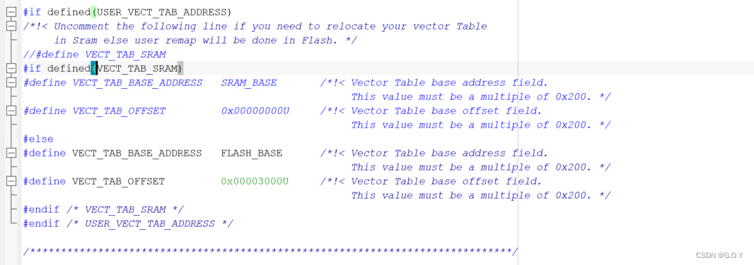
中断向量表的偏移是依靠HAL库的配置文件实现的:system_stm32f1xx.c
- 将VECT_TAB_OFFSET 修改为0x00003000U
- 选择FLASH_BASE地址
编译地址偏移
这个主要是根据IAR项目中的连接文件:.icf配置的:
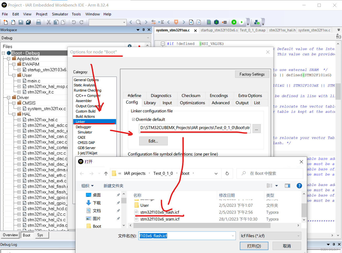 修改的地方如下:
- ICFEDIT_intvec_start
- ICFEDIT_region_ROM_start
- ICFEDIT_region_ROM_end
/*###ICF### Section handled by ICF editor, don't touch! ****/
/*-Editor annotation file-*/
/* IcfEditorFile="$TOOLKIT_DIR$\config\ide\IcfEditor\cortex_v1_0.xml" */
/*-Specials-*/
define symbol __ICFEDIT_intvec_start__ = 0x08003000;   //app修改
define symbol __ICFEDIT_intvec_start__ = 0x08000000;   //boot保持
/*-Memory Regions-*/
define symbol __ICFEDIT_region_ROM_start__ = 0x08003000 ; //app修改
define symbol __ICFEDIT_region_ROM_start__ = 0x08000000 ; //boot保持
define symbol __ICFEDIT_region_ROM_end__   = 0x08007FFF; //app保持
define symbol __ICFEDIT_region_ROM_end__   = 0x08003000; //boot修改
define symbol __ICFEDIT_region_RAM_start__ = 0x20000000;
define symbol __ICFEDIT_region_RAM_end__   = 0x200027FF;
/*-Sizes-*/
define symbol __ICFEDIT_size_cstack__ = 0x400;
define symbol __ICFEDIT_size_heap__   = 0x200;
/**** End of ICF editor section. ###ICF###*/


define memory mem with size = 4G;
define region ROM_region   = mem:[from __ICFEDIT_region_ROM_start__   to __ICFEDIT_region_ROM_end__];
define region RAM_region   = mem:[from __ICFEDIT_region_RAM_start__   to __ICFEDIT_region_RAM_end__];

define block CSTACK    with alignment = 8, size = __ICFEDIT_size_cstack__   { };
define block HEAP      with alignment = 8, size = __ICFEDIT_size_heap__     { };

initialize by copy { readwrite };
do not initialize  { section .noinit };

place at address mem:__ICFEDIT_intvec_start__ { readonly section .intvec };

place in ROM_region   { readonly };
place in RAM_region   { readwrite,
                        block CSTACK, block HEAP };
最后在app添加一个无线循环串口发送:
uint8_t Temp_buff[] = "GOOD DAY!!\r\n";
int main(void)
{

  /* USER CODE BEGIN 1 */

  /* USER CODE END 1 */

  /* MCU Configuration--------------------------------------------------------*/

  /* Reset of all peripherals, Initializes the Flash interface and the Systick. */
  HAL_Init();

  /* USER CODE BEGIN Init */

  /* USER CODE END Init */

  /* Configure the system clock */
  SystemClock_Config();

  /* USER CODE BEGIN SysInit */

  /* USER CODE END SysInit */

  /* Initialize all configured peripherals */
  MX_GPIO_Init();
  MX_USART1_UART_Init();

  /* USER CODE BEGIN 2 */

  /* USER CODE END 2 */

  /* Infinite loop */
  /* USER CODE BEGIN WHILE */
  while (1)
  {
    /* USER CODE END WHILE */
    HAL_UART_Transmit(&huart1,(uint8_t *)&Temp_buff,15,0xff);
    /* USER CODE BEGIN 3 */
  }
  /* USER CODE END 3 */
}
生成hex。
四 烧录:
到这里我们手里已经有了app.hex和sys.hex文件了,我们可以合成文件了,这里我引用别人的博客:hex合并
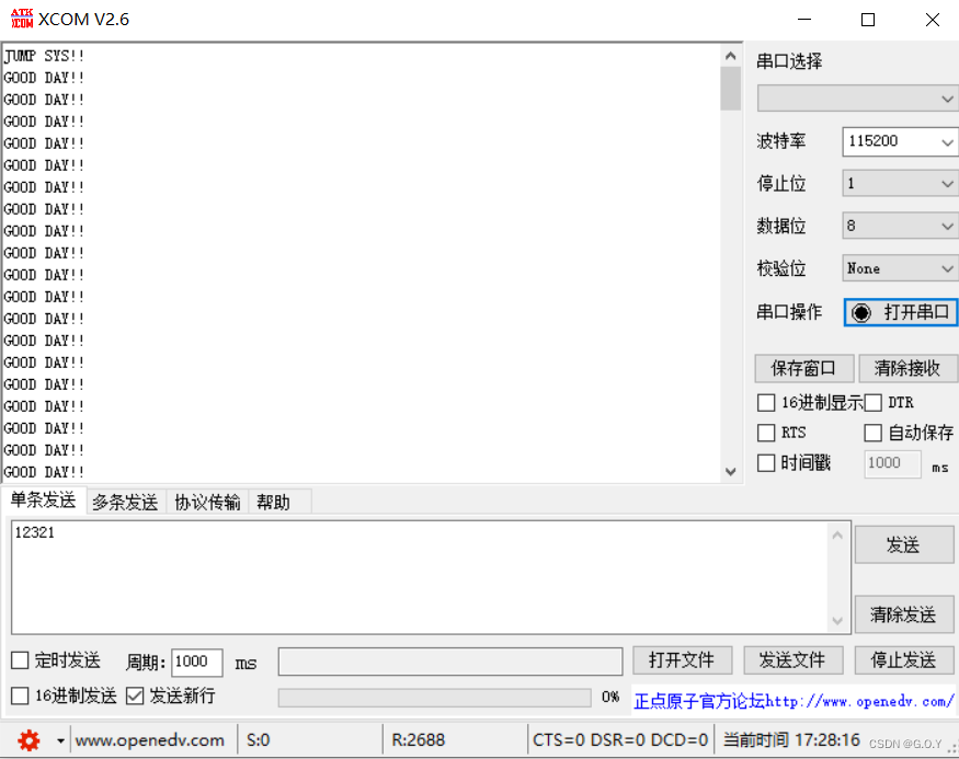
推荐使用j-flash,合成完成后,使用STM32 ST-LINK Utility,将它烧录到小蓝板中,使用串口接收,发现和预期一样:




![P3029 [USACO11NOV]Cow Lineup S 双指针 单调队列](https://img-blog.csdnimg.cn/6af1894944f542299edaa735404b58a3.png)
![[MAUI]模仿iOS应用多任务切换卡片滑动的交互实现](https://img-blog.csdnimg.cn/6fca7de1f85646dc894e72f43390f317.gif)

