文章目录
O C V OCV OCV,全称 O n C h i p V a r i a t i o n On\ Chip\ Variation On Chip Variation(10.1 片上变化(On-Chip Variations)),是用于 s i g n o f f signoff signoff过程中为了弥补工艺制造过程中的不稳定情况的技术。
1. O v e r v i e w Overview Overview
1.1 w h a t i s o c v what\ is\ ocv what is ocv?
O n C h i p V a r i a t i o n On\ Chip\ Variation On Chip Variation,片上偏差。如下图左侧 w a f e r wafer wafer上面的红色/黄色/绿色框框所示,虽然在一片 w a f e r wafer wafer上,但是因为位于不同的区域,因此在制造过程中总会有这样那样的差别,比如机器没控制好,红框沉积量要比黄框大一个百分比,比如绿框刻蚀的时候稍微严重了一些,等等情况导致 w a f e r wafer wafer上的所有的 d i e die die不尽相同。我们称之为 v a r i a t i o n variation variation。右侧图所示为一个 d i e die die的放大图, v a r i a t i o n variation variation在芯片上的影响就是对 c e l l cell cell和 n e t net net真实 d e l a y delay delay的影响,那这个就会导致我们真实的 s t d c e l l std\ cell std cell相关 d e l a y delay delay和 f o u n d r y foundry foundry提供的标准单元库的相关 d e l a y delay delay有偏差,可能造成芯片的 f a i l fail fail。为了 c o v e r cover cover这种 v a r i a t i o n variation variation,我们在 S T A s i g n o f f STA\ signoff STA signoff时候引入了 O C V OCV OCV的技术,使得我们的 s i g n o f f signoff signoff更加严格,从而影响工艺制造过程中的影响。一个技术,即使再先进,也是会有误差的。尤其是工艺从百 n s ns ns级别到 n s ns ns级别,些许的误差对于制造效果来说都影响巨大。

1.2 O C V . E f f e c t o n s i g n o f f OCV.\ Effect\ on\ signoff OCV. Effect on signoff
上面提到, v a r i a t i o n variation variation会对 t i m i n g s i g n o f f timing\ signoff timing signoff产生影响,具体如何影响的详细介绍如下:
- N o m a l m o d e t i m i n g s i g n o f f Nomal\ mode\ timing\ signoff Nomal mode timing signoff(不考虑 O C V OCV OCV)
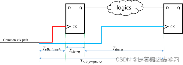
如上图所示为不考虑 O C V OCV OCV情况下的 t i m i n g s i g n o f f timing\ signoff timing signoff ,这时候进行 s e t u p t i m i n g c h e c k setup\ timing\ check setup timing check,如果满足图中的公式,就认为时序是没有问题的。

- O C V m o d e t i m i n g s i g n o f f OCV\ mode\ timing\ signoff OCV mode timing signoff
当我们考虑了实际的制造过程,那么会出现如下的情况,如下图所示存在与 l a u n c h p a t h launch path launchpath上的 c e l l cell cell可能就比我们拿到的 s t d c e l l std\ cell std cell的 d e l a y delay delay值要大一些,而存在与 c a p t u r e p a t h capture\ path capture path的 s t d c e l l std\ cell std cell的 d e l a y delay delay值要比 s t d c e l l std\ cell std cell的小一些。
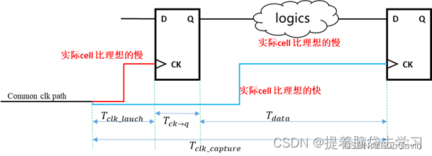
如果我们把 v a r i a t i o n variation variation有具体的数值表示:增加 l a u c h c l k d e l a y lauch\ clk\ delay lauch clk delay和 d a t a p a t h d e l a y Δ 1 data\ path\ delay\ \Delta1 data path delay Δ1,减少 c a p t u r e p a t h d e l a y Δ 2 capture\ path\ delay\ \Delta2 capture path delay Δ2,那么重新作用到 s e t u p setup setup的计算公式上如下图所示,可以看到这两个 Δ \Delta Δ的加入是有可能导致我们这个不等式不成立的,也就是说真实的工作时候,可能是不满足 s e t u p t i m i n g setup \ timing setup timing检查的,就有可能导致芯片的 f a i l fail fail。

1.3 H o w t o r e m o v e t h e e f f e c t s o f O C V How\ to\ remove\ the\ effects\ of\ OCV How to remove the effects of OCV
上面1.2介绍了 o c v ocv ocv对 s i g n o f f signoff signoff的影响,那么如何消除这个影响呢?可以通过增加 m a r g i n margin margin的方式,其实和 u n c e r t a i n t y uncertainty uncertainty非常相似,就是通过把我们的 c h e c k check check变得更加严格,从而来消除这种影响。 O C V OCV OCV的消除方法是通过设置 d e r a t e derate derate值。比如:对于 l a u n c h c l o c k launch\ clock launch clock,加上一个统一的大于 1 1 1的 d e r a t e derate derate值,就会在 t i m i n g r e p o r t timing\ report timing report中反映出来,相应的 d e l a y delay delay也会在原始值的基础上乘以这个 d e r a t e derate derate值,相当于增大了 l a u n c h p a t h launch\ path launch path的 d e l a y delay delay,而对于 c a p t u r e c l o c k p a t h capture\ clock\ path capture clock path,相应地就会加上一个小于 1 1 1的 d e r a t e derate derate来计算 d e l a y delay delay,从而减小 l a u n c h p a t h launch\ path launch path的 d e l a y delay delay。通过这样的方法来让时序约束更加悲观,以此来覆盖生产中和实际应用中的各种 v a r i a t i o n variation variation。那需不需要考虑减小 l a u n c h p a t h launch\ path launch path,增大 c a p t u r e p a t h capture\ path capture path的情况呢?对于 s e t u p setup setup肯定是不需要的,但是对于 h o l d hold hold是需要的。接下来将会详细介绍 d e r a t e derate derate设定的情况。
2. O C V a p p l i e d a n d r e s u l t s OCV\ applied\ and\ results OCV applied and results
2.1 O C V a p p l i e d OCV\ applied OCV applied
具体的 O C V OCV OCV的实现方法以及效果是如何的呢,这个小部分展开讨论一下。

对 l a u n c h , c a p t u r e launch, capture launch,capture和 d a t a p a t h data path datapath上的 c e l l cell cell或者 n e t net net加一个固定的 d e r a t e derate derate数值,使得 s e t u p setup setup和 h o l d hold hold等时序约束比理想状况更加悲观从而能够覆盖部分实际生产中所产生的 v a r i a t i o n variation variation。如上图所示,针对于 s e t u p c h e c k setup\ check setup check,所有的 l a u n c h p a t h launch\ path launch path设置 d e r a t e derate derate为 1.1 1.1 1.1,所有的 c a p t u r e p a t h capture\ path capture path的 d e r a t e derate derate值设置为 0.9 0.9 0.9。我们在做 h o l d c h e c k hold\ check hold check时候,那么就会和 s e t u p setup setup时候恰恰相反, l a u n c h p a t h launch\ path launch path设置 d e r a t e derate derate为 0.9 0.9 0.9,所有的 c a p t u r e p a t h capture\ path capture path的 d e r a t e derate derate值设置为 1.1 1.1 1.1。
如何实现这个设置呢,可以通过在 S D C SDC SDC中增加如下命令的方式:
set_timing_derate -early 0.9
set_timing_derate -late 1.1
当设置这两个
d
e
r
a
t
e
derate
derate时候,-early表明我们期望最短的
p
a
t
h
path
path,也就是期望最严格的检查,那么在
s
e
t
u
p
setup
setup时候,当然
c
a
p
t
u
r
e
p
a
t
h
capture\ path
capture path越短越严格,同理,
h
o
l
d
hold
hold的时候
l
a
u
n
c
h
p
a
t
h
launch\ path
launch path 越短越严格。-late恰恰相反。除此之外,关于set_timing_derate的命令还有很多的写法如下所示,-data/clock表示这个
d
e
r
a
t
e
derate
derate作用于
c
l
o
c
k
p
a
t
h
clock\ path
clock path还是
d
a
t
a
p
a
t
h
data\ path
data path,cell delay/net_delay表示作用于
c
e
l
l
cell
cell还是
n
e
t
net
net:
set_timing_derate -early 0.9 –clock/data
set_timing_derate -net_delay/cell_delay -late 1.1
set_timing_derate -cell_delay -early 0.9
2.2 T i m i n g r e p o r t Timing\ report Timing report
如下图示例很清晰的讲解了 d e r a t e derate derate如何作用于 t i m i n g s i g n o f f timing\ signoff timing signoff的情况。图中所示标识了 c o m m o n c l o c k p a t h d e l a y common\ clock\ path\ delay common clock path delay为 1.2 n s 1.2ns 1.2ns, l a u n c h c l o c k d e l a y launch\ clock\ delay launch clock delay为 0.8 n s 0.8ns 0.8ns, d a t a p a t h data\ path data path为 5.2 n s 5.2ns 5.2ns, c a p t u r e c l o c k d e l a y capture\ clock\ delay capture clock delay为 0.86 n s 0.86ns 0.86ns, T s e t u p T_{setup} Tsetup为 0.35 n s 0.35ns 0.35ns。

若按照Nomal mode timing进行setup timing check,及不包括任何用于降额延迟的 O C V OCV OCV设置:
LaunchClockPath + MaxDataPath <= ClockPeriod +
	CaptureClockPath - Tsetup_UFF1

This implies that the minimum clock period = LaunchClockPath +
	MaxDataPath - CaptureClockPath + Tsetup_UFF1

From the figure,
	LaunchClockPath = 1.2 + 0.8 = 2.0
	MaxDataPath = 5.2
	CaptureClockPath = 1.2 + 0.86 = 2.06
	Tsetup_UFF1 = 0.35

This results in a minimum clock period of:
	2.0 + 5.2 – 2.06 + 0.35 = 5.49ns
而当设定如下所示的 d e r a t e derate derate后,那么刚刚描述的内容会发生变化:
set_timing_derate -early 0.9
set_timing_derate -late 1.2
set_timing_derate -late 1.1 -cell_check
此时:
Launch Path = (LaunchClockPath + MaxDataPath) * lateDerate =
	((1.2+0.8)+5.2)*1.2 = 8.64ns
Capture Path = (CaptureClockPath) * earlyDerate =
	(1.2+0.86)*0.9+0.351 = 2.239ns
=> MinClockPeriod = 8.64-2.239 = 6.401ns
而因为 c o m m o n p a t h common\ path common path有 1.2 n s 1.2ns 1.2ns的公共部分,过于悲观,去掉这一部分,这个过程叫做 C R P R CRPR CRPR(10.1 片上变化(On-Chip Variations)),去除悲观度。那么真实的可以达到的最小时钟周期 T = 6.401 − 1.2 ( 1.2 − 0.9 ) = 6.041 T = 6.401 - 1.2(1.2-0.9) = 6.041 T=6.401−1.2(1.2−0.9)=6.041。
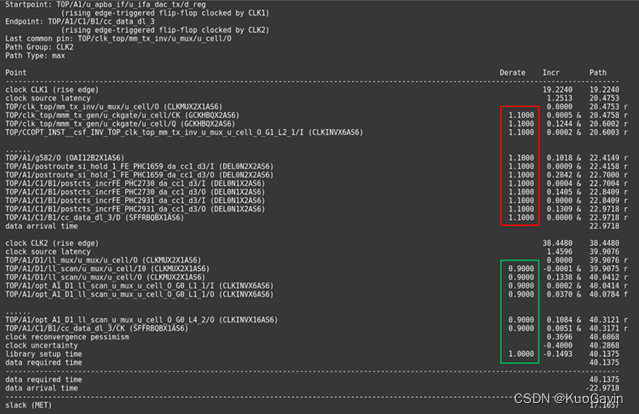
而真实的 d e r a t e derate derate值在 t i m i n g timing timing报告中应该是如下图所示:
