Building a visual robot model from scratch
在本教程中,我们将构建一个机器人的视觉模型,它看起来有点像R2D2。 在后面的教程中,您将学习如何 清晰地表达模型,添加一些物理属性,并使用xacro生成更简洁的代码,但现在,我们将专注于获得正确的可视几何图形。
在继续之前,请确保已安装joint_state_publisher软件包。 如果您安装了urdf_tutorial二进制文件,则应该已经是这种情况。 如果没有,请更新您的安装以包含该软件包(使用rosdep检查)。
本教程中提到的所有机器人模型(以及源文件)都可以在urdf_tutorial包中找到。
One Shape
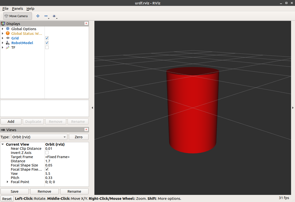
首先,我们将探索一个简单的形状。 这是你能做的最简单的一个urdf。
<?xml version="1.0"?>
<robot name="myfirst">
  <link name="base_link">
    <visual>
      <geometry>
        <cylinder length="0.6" radius="0.2"/>
      </geometry>
    </visual>
  </link>
</robot>为了将XML翻译成英语,这是一个机器人,其名称为myfirst,它只包含一个link(也称为部分),其视觉组件只是一个0.6米长、0.2米半径的圆柱体。 对于一个简单的“hello world”类型的例子来说,这看起来像是很多封闭的标记,但是相信我,它会变得更复杂。
要检查模型,请启动display.launch.py文件:
ros2 launch urdf_tutorial display.launch.py model:=urdf/01-myfirst.urdf-
加载指定的模型并将其另存为参数
-
运行节点以发布sensor_msgs/msg/JointState和转换(稍后将详细介绍)
-
Starts Rviz with a configuration file使用配置文件启动Rviz
请注意,上面的启动命令假定您是从urdf_tutorialpackage目录(即:urdf目录是当前工作目录的直接子目录)。 如果不是这样的话,到01-myfirst.urdf的相对路径将是无效的,并且一旦启动器试图将urdf作为参数加载,您就会收到一个错误。
个稍微修改的参数允许它工作,而不管当前的工作目录:
ros2 launch urdf_tutorial display.launch.py model:=`ros2 pkg prefix --share urdf_tutorial`/urdf/01-myfirst.urdf如果您不是从urdf_tutorial包位置运行这些教程中给出的所有示例启动命令,则必须更改它们。
在启动display.launch.py之后,您应该会看到RViz显示以下内容:
Multiple Shapes
现在让我们看看如何添加多个shape/link。 如果我们只是向urdf添加更多的link元素,解析器将不知道把它们放在哪里。 所以,我们必须增加关节。 接头元件可以指柔性接头和非柔性接头两者。 我们将从不灵活的或固定的关节开始。
<?xml version="1.0"?>
<robot name="multipleshapes">
  <link name="base_link">
    <visual>
      <geometry>
        <cylinder length="0.6" radius="0.2"/>
      </geometry>
    </visual>
  </link>

  <link name="right_leg">
    <visual>
      <geometry>
        <box size="0.6 0.1 0.2"/>
      </geometry>
    </visual>
  </link>

  <joint name="base_to_right_leg" type="fixed">
    <parent link="base_link"/>
    <child link="right_leg"/>
  </joint>

</robot>-
注意我们如何定义一个0.6m x 0.1m x 0.2m的盒子
-
运动类型是根据父对象和子对象定义的。 URDF最终是具有一个根链路的树结构。 这意味着腿的位置取决于base_link的位置。
ros2 launch urdf_tutorial display.launch.py model:=urdf/02-multipleshapes.urdf
这两个形状彼此重叠,因为它们共享同一原点。 如果希望它们不重叠,就必须定义更多原点。
Origins
R2D2的腿连接到他躯干的上半部分,在侧面。 这就是我们指定JOINT的原点的位置。 此外,它不连接到腿的中间,它连接到上部,所以我们也必须偏移腿的原点。 我们还旋转腿,使其直立。 [源代码:eglibc. com]
<?xml version="1.0"?>
<robot name="origins">
  <link name="base_link">
    <visual>
      <geometry>
        <cylinder length="0.6" radius="0.2"/>
      </geometry>
    </visual>
  </link>

  <link name="right_leg">
    <visual>
      <geometry>
        <box size="0.6 0.1 0.2"/>
      </geometry>
      <origin rpy="0 1.57075 0" xyz="0 0 -0.3"/>
    </visual>
  </link>

  <joint name="base_to_right_leg" type="fixed">
    <parent link="base_link"/>
    <child link="right_leg"/>
    <origin xyz="0 -0.22 0.25"/>
  </joint>

</robot>-
让我们从检查关节的原点开始。 它是根据父对象的参考系定义的。 所以我们在y方向上是-0.22米(向左,但相对于轴是向右),在z方向上是0.25米(向上)。 这意味着子链接的原点将位于右上方,而不管子链接的可视原点标记是什么。 因为我们没有指定rpy(roll pitch yaw)属性,所以子帧将默认与父帧具有相同的方向。
-
现在,查看腿部的视觉原点,它同时具有xyz和rpy偏移。 这定义了视觉元素的中心相对于其原点的位置。 由于我们希望腿附着在顶部,因此通过将z偏移设置为-0.3米来向下偏移原点。 由于我们希望腿的长部分平行于z轴,因此我们围绕Y轴旋转视觉部分PI/2。
ros2 launch urdf_tutorial display.launch.py model:=urdf/03-origins.urdf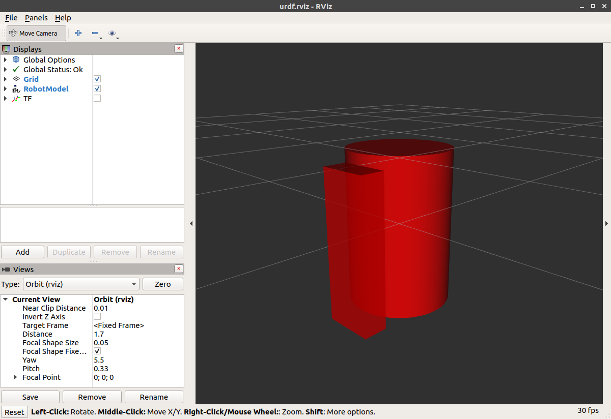
-
启动文件运行的包将根据URDF为模型中的每个链接创建TF帧。 Rviz使用这些信息来确定每个形状的显示位置。
-
如果对于给定的URDF链路不存在TF帧,则它将以白色放置在原点处(参考相关问题)。
Material Girl
好吧”我听到你说 “这很可爱,但不是每个人都拥有B21。 我的机器人和R2D2不是红色的!” 说得对 让我们来看看材质标签。 [源代码:eglibc. com]
<?xml version="1.0"?>
<robot name="materials">

  <material name="blue">
    <color rgba="0 0 0.8 1"/>
  </material>

  <material name="white">
    <color rgba="1 1 1 1"/>
  </material>

  <link name="base_link">
    <visual>
      <geometry>
        <cylinder length="0.6" radius="0.2"/>
      </geometry>
      <material name="blue"/>
    </visual>
  </link>

  <link name="right_leg">
    <visual>
      <geometry>
        <box size="0.6 0.1 0.2"/>
      </geometry>
      <origin rpy="0 1.57075 0" xyz="0 0 -0.3"/>
      <material name="white"/>
    </visual>
  </link>

  <joint name="base_to_right_leg" type="fixed">
    <parent link="base_link"/>
    <child link="right_leg"/>
    <origin xyz="0 -0.22 0.25"/>
  </joint>

  <link name="left_leg">
    <visual>
      <geometry>
        <box size="0.6 0.1 0.2"/>
      </geometry>
      <origin rpy="0 1.57075 0" xyz="0 0 -0.3"/>
      <material name="white"/>
    </visual>
  </link>

  <joint name="base_to_left_leg" type="fixed">
    <parent link="base_link"/>
    <child link="left_leg"/>
    <origin xyz="0 0.22 0.25"/>
  </joint>

</robot>-
身体现在是蓝色的。 我们定义了一种新的材质“blue”,红色、绿色、蓝色和alpha通道分别定义为0、0、0.8和1。 所有值可以在范围[0,1]中。 这个素材然后被base_link的可视元素引用。 白色材料的定义类似。
-
您还可以从可视元素中定义材质标记,甚至可以在其他链接中引用它。 如果你重新定义它,没有人会抱怨。
-
您还可以使用纹理来指定用于为对象着色的图像文件
ros2 launch urdf_tutorial display.launch.py model:=urdf/04-materials.urdf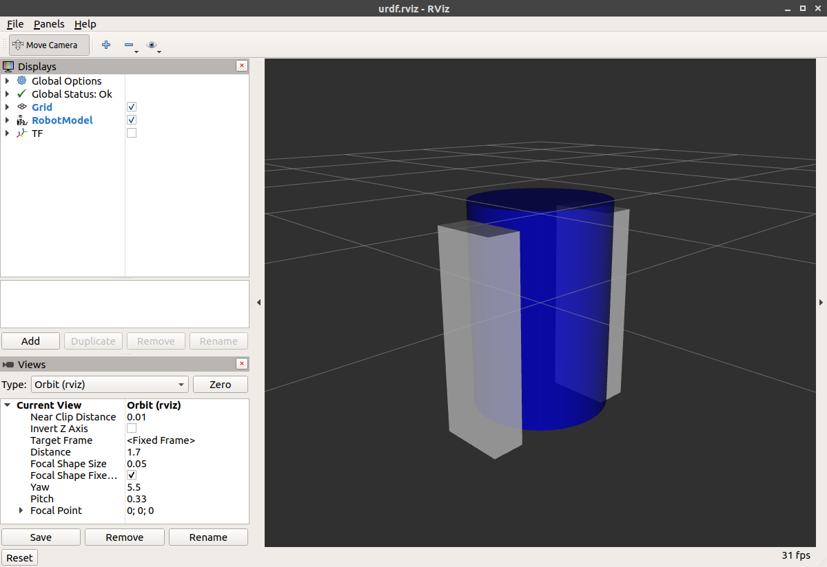
Finishing the Model
现在,我们完成了几个形状的模型:脚,轮子,和头。 最值得注意的是,我们添加了一个球体和一些网格。 我们还将添加一些稍后使用的其他部分。 [源代码:eglibc. com]
<?xml version="1.0"?>
<robot name="visual">

  <material name="blue">
    <color rgba="0 0 0.8 1"/>
  </material>
  <material name="black">
    <color rgba="0 0 0 1"/>
  </material>
  <material name="white">
    <color rgba="1 1 1 1"/>
  </material>

  <link name="base_link">
    <visual>
      <geometry>
        <cylinder length="0.6" radius="0.2"/>
      </geometry>
      <material name="blue"/>
    </visual>
  </link>

  <link name="right_leg">
    <visual>
      <geometry>
        <box size="0.6 0.1 0.2"/>
      </geometry>
      <origin rpy="0 1.57075 0" xyz="0 0 -0.3"/>
      <material name="white"/>
    </visual>
  </link>

  <joint name="base_to_right_leg" type="fixed">
    <parent link="base_link"/>
    <child link="right_leg"/>
    <origin xyz="0 -0.22 0.25"/>
  </joint>

  <link name="right_base">
    <visual>
      <geometry>
        <box size="0.4 0.1 0.1"/>
      </geometry>
      <material name="white"/>
    </visual>
  </link>

  <joint name="right_base_joint" type="fixed">
    <parent link="right_leg"/>
    <child link="right_base"/>
    <origin xyz="0 0 -0.6"/>
  </joint>

  <link name="right_front_wheel">
    <visual>
      <origin rpy="1.57075 0 0" xyz="0 0 0"/>
      <geometry>
        <cylinder length="0.1" radius="0.035"/>
      </geometry>
      <material name="black"/>
    </visual>
  </link>
  <joint name="right_front_wheel_joint" type="fixed">
    <parent link="right_base"/>
    <child link="right_front_wheel"/>
    <origin rpy="0 0 0" xyz="0.133333333333 0 -0.085"/>
  </joint>

  <link name="right_back_wheel">
    <visual>
      <origin rpy="1.57075 0 0" xyz="0 0 0"/>
      <geometry>
        <cylinder length="0.1" radius="0.035"/>
      </geometry>
      <material name="black"/>
    </visual>
  </link>
  <joint name="right_back_wheel_joint" type="fixed">
    <parent link="right_base"/>
    <child link="right_back_wheel"/>
    <origin rpy="0 0 0" xyz="-0.133333333333 0 -0.085"/>
  </joint>

  <link name="left_leg">
    <visual>
      <geometry>
        <box size="0.6 0.1 0.2"/>
      </geometry>
      <origin rpy="0 1.57075 0" xyz="0 0 -0.3"/>
      <material name="white"/>
    </visual>
  </link>

  <joint name="base_to_left_leg" type="fixed">
    <parent link="base_link"/>
    <child link="left_leg"/>
    <origin xyz="0 0.22 0.25"/>
  </joint>

  <link name="left_base">
    <visual>
      <geometry>
        <box size="0.4 0.1 0.1"/>
      </geometry>
      <material name="white"/>
    </visual>
  </link>

  <joint name="left_base_joint" type="fixed">
    <parent link="left_leg"/>
    <child link="left_base"/>
    <origin xyz="0 0 -0.6"/>
  </joint>

  <link name="left_front_wheel">
    <visual>
      <origin rpy="1.57075 0 0" xyz="0 0 0"/>
      <geometry>
        <cylinder length="0.1" radius="0.035"/>
      </geometry>
      <material name="black"/>
    </visual>
  </link>
  <joint name="left_front_wheel_joint" type="fixed">
    <parent link="left_base"/>
    <child link="left_front_wheel"/>
    <origin rpy="0 0 0" xyz="0.133333333333 0 -0.085"/>
  </joint>

  <link name="left_back_wheel">
    <visual>
      <origin rpy="1.57075 0 0" xyz="0 0 0"/>
      <geometry>
        <cylinder length="0.1" radius="0.035"/>
      </geometry>
      <material name="black"/>
    </visual>
  </link>
  <joint name="left_back_wheel_joint" type="fixed">
    <parent link="left_base"/>
    <child link="left_back_wheel"/>
    <origin rpy="0 0 0" xyz="-0.133333333333 0 -0.085"/>
  </joint>

  <joint name="gripper_extension" type="fixed">
    <parent link="base_link"/>
    <child link="gripper_pole"/>
    <origin rpy="0 0 0" xyz="0.19 0 0.2"/>
  </joint>

  <link name="gripper_pole">
    <visual>
      <geometry>
        <cylinder length="0.2" radius="0.01"/>
      </geometry>
      <origin rpy="0 1.57075 0 " xyz="0.1 0 0"/>
    </visual>
  </link>

  <joint name="left_gripper_joint" type="fixed">
    <origin rpy="0 0 0" xyz="0.2 0.01 0"/>
    <parent link="gripper_pole"/>
    <child link="left_gripper"/>
  </joint>

  <link name="left_gripper">
    <visual>
      <origin rpy="0.0 0 0" xyz="0 0 0"/>
      <geometry>
        <mesh filename="package://urdf_tutorial/meshes/l_finger.dae"/>
      </geometry>
    </visual>
  </link>

  <joint name="left_tip_joint" type="fixed">
    <parent link="left_gripper"/>
    <child link="left_tip"/>
  </joint>

  <link name="left_tip">
    <visual>
      <origin rpy="0.0 0 0" xyz="0.09137 0.00495 0"/>
      <geometry>
        <mesh filename="package://urdf_tutorial/meshes/l_finger_tip.dae"/>
      </geometry>
    </visual>
  </link>
  <joint name="right_gripper_joint" type="fixed">
    <origin rpy="0 0 0" xyz="0.2 -0.01 0"/>
    <parent link="gripper_pole"/>
    <child link="right_gripper"/>
  </joint>

  <link name="right_gripper">
    <visual>
      <origin rpy="-3.1415 0 0" xyz="0 0 0"/>
      <geometry>
        <mesh filename="package://urdf_tutorial/meshes/l_finger.dae"/>
      </geometry>
    </visual>
  </link>

  <joint name="right_tip_joint" type="fixed">
    <parent link="right_gripper"/>
    <child link="right_tip"/>
  </joint>

  <link name="right_tip">
    <visual>
      <origin rpy="-3.1415 0 0" xyz="0.09137 0.00495 0"/>
      <geometry>
        <mesh filename="package://urdf_tutorial/meshes/l_finger_tip.dae"/>
      </geometry>
    </visual>
  </link>

  <link name="head">
    <visual>
      <geometry>
        <sphere radius="0.2"/>
      </geometry>
      <material name="white"/>
    </visual>
  </link>
  <joint name="head_swivel" type="fixed">
    <parent link="base_link"/>
    <child link="head"/>
    <origin xyz="0 0 0.3"/>
  </joint>

  <link name="box">
    <visual>
      <geometry>
        <box size="0.08 0.08 0.08"/>
      </geometry>
      <material name="blue"/>
    </visual>
  </link>

  <joint name="tobox" type="fixed">
    <parent link="head"/>
    <child link="box"/>
    <origin xyz="0.1814 0 0.1414"/>
  </joint>
</robot>
ros2 launch urdf_tutorial display.launch.py model:=urdf/05-visual.urdf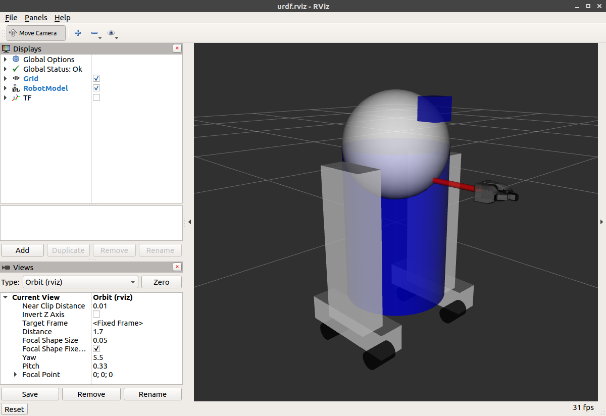
如何添加球体应该是相当自我解释的:
<link name="head">
  <visual>
    <geometry>
      <sphere radius="0.2"/>
    </geometry>
    <material name="white"/>
  </visual>
</link>
这里的网格是从PR2借用的。 它们是单独的文件,您必须为其指定路径。 你应该使用package://NAME_OF_PACKAGE/path符号。 本教程的网格位于urdf_tutorial包中名为meshes的文件夹中。
<link name="left_gripper">
  <visual>
    <origin rpy="0.0 0 0" xyz="0 0 0"/>
    <geometry>
      <mesh filename="package://urdf_tutorial/meshes/l_finger.dae"/>
    </geometry>
  </visual>
</link>-
网格可以以多种不同的格式导入。 STL是相当常见的,但引擎也支持DAE,它可以有自己的颜色数据,这意味着你不必指定颜色/材料。 这些文件通常位于单独的文件中。 这些网格也参照网格文件夹中的
.tif文件。 -
也可以使用相对缩放参数或边界框大小来调整网格的大小。
-
我们也可以在一个完全不同的包中引用网格。
Building a movable robot model
urdf模型中joint 的类型
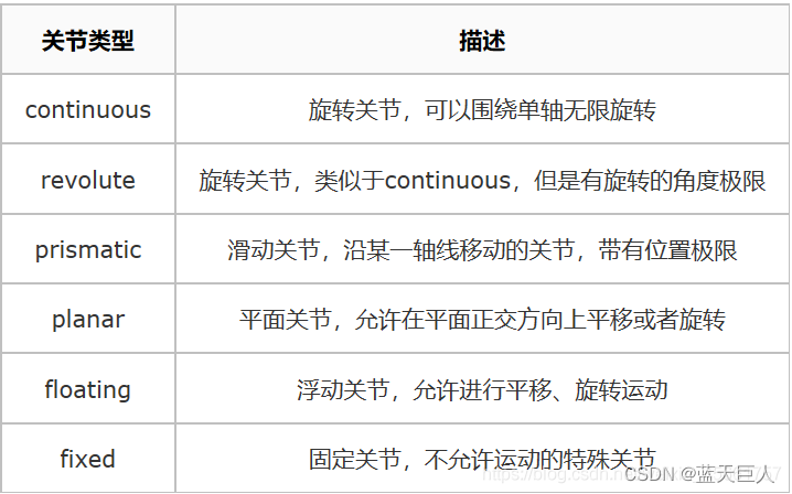
在本教程中,我们将修改我们在 上一教程 所以它有活动关节。 在之前的模型中,所有关节都是固定的。 现在,我们将探索其他三种重要类型的关节:continuous, revolute and prismatic。
继续之前,请确保已安装所有必备组件。 见 上一教程 了解所需的信息。
同样,本教程中提到的所有机器人模型都可以在urdf_tutorial包中找到。
这是一个新的带有灵活连接的urdf。 您可以将其与以前的版本进行比较,以查看更改的所有内容,但我们只关注三个示例关节。
要可视化和控制此模型,请运行与上一个教程相同的命令:
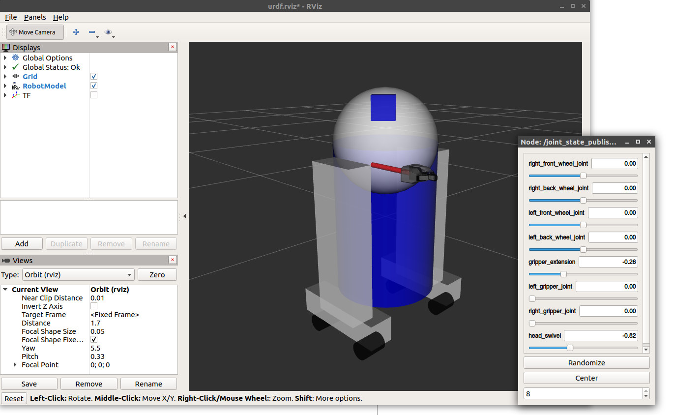
ros2 launch urdf_tutorial display.launch.py model:=urdf/06-flexible.urdf但是现在这也将弹出一个GUI,允许您控制所有非固定关节的值。 玩一下这个模型,看看它是如何移动的。 然后,我们可以看看我们是如何做到这一点的。
The Head
<joint name="head_swivel" type="continuous">
  <parent link="base_link"/>
  <child link="head"/>
  <axis xyz="0 0 1"/>
  <origin xyz="0 0 0.3"/>
</joint>身体和头部之间的连接是一个 continuous joint,,这意味着它可以呈现从负无穷大到正无穷大的任何角度。 轮子也是这样建模的,这样它们就可以永远向两个方向滚动。
我们必须添加的唯一附加信息是旋转轴,在这里由xyz三元组指定,该三元组指定头部将围绕其旋转的向量。 因为我们希望它绕z轴运动,所以我们指定向量“0 0 1”。
The Gripper
<joint name="left_gripper_joint" type="revolute">
  <axis xyz="0 0 1"/>
  <limit effort="1000.0" lower="0.0" upper="0.548" velocity="0.5"/>
  <origin rpy="0 0 0" xyz="0.2 0.01 0"/>
  <parent link="gripper_pole"/>
  <child link="left_gripper"/>
</joint>左右夹持器关节均建模为revolute joints.。 这意味着它们的旋转方式与连续关节相同,但它们具有严格的限制。 因此,我们必须包括限制标签,指定关节的上限和下限(以弧度为单位)。 我们还必须指定该关节的最大速度和作用力,但实际值与我们的目的无关。
The Gripper Arm
<joint name="gripper_extension" type="prismatic">
  <parent link="base_link"/>
  <child link="gripper_pole"/>
  <limit effort="1000.0" lower="-0.38" upper="0" velocity="0.5"/>
  <origin rpy="0 0 0" xyz="0.19 0 0.2"/>
</joint>
夹持器臂是不同类型的接头,即 prismatic joint.。 这意味着它沿着轴移动,而不是围绕轴移动。 这种平移运动允许我们的机器人模型延伸和缩回其夹持臂。
棱柱臂的限制的指定方式与旋转运动类型相同,不同之处在于单位是米,而不是弧度。
Other Types of Joints
还有另外两种关节在空间中移动。 棱柱运动类型只能沿着一个维度移动,而平面运动类型可以在平面或两个维度中移动。 此外,浮动运动类型不受约束,可以在三个维度中的任意维度上移动。 这些运动类型不能仅由一个数字指定,因此不包含在本教程中。
Specifying the Pose
在GUI中移动滑块时,模型在Rviz中移动。 这是怎么做到的?首先,GUI解析URDF并查找所有非固定关节及其限制。 然后,它使用滑块的值发布sensor_msgs/msg/JointState消息。 然后 robot_state_publisher使用它们来计算不同部分之间的所有变换。 然后使用生成的变换树来显示Rviz中的所有形状。
Adding physical and collision properties
目标:了解如何向链接添加碰撞和惯性特性,以及如何向关节添加关节动力学。
在本教程中,我们将研究如何向URDF模型添加一些基本的物理属性,以及如何指定其碰撞属性。
Collision
到目前为止,我们只使用一个子元素visual指定了链接,该子元素定义了(并不奇怪)机器人的外观。 然而,为了让碰撞检测工作或模拟机器人,我们还需要定义一个collision元素。 这是一个新的带有碰撞和物理属性的urdf。
<link name="base_link">
    <visual>
      <geometry>
        <cylinder length="0.6" radius="0.2"/>
      </geometry>
      <material name="blue">
        <color rgba="0 0 .8 1"/>
      </material>
    </visual>
    <collision>
      <geometry>
        <cylinder length="0.6" radius="0.2"/>
      </geometry>
    </collision>
</link>-
碰撞元素是链接对象的直接子元素,与视觉标记处于同一级别。
-
碰撞元素定义其形状的方式与视觉元素相同,即使用几何图形标记。 此处几何体标记的格式与视觉标记的格式完全相同。
-
也可以使用与碰撞标记的子元素相同的方式指定原点(与视觉对象一样)。
在许多情况下,您会希望碰撞几何体和原点与可视几何体和原点完全相同。 但是,有两种主要情况下,你不会:
更快的处理。对两个网格进行碰撞检测比对两个简单几何体进行碰撞检测要复杂得多。 因此,您可能希望在碰撞元素中使用更简单的几何体替换网格。
安全区。您可能需要限制靠近敏感设备的移动。 例如,如果我们不希望任何物体与R2D2的头部碰撞,我们可以将碰撞几何体定义为一个包围其头部的圆柱体,以防止任何物体过于靠近其头部。
Physical Properties
为了使模型正确模拟,需要定义机器人的多个物理属性,即 像Gazebo这样的物理引擎所需要的属性。
Inertia
每个被模拟的链接元素都需要一个惯性标签。 这里有一个简单的例子。
<link name="base_link">
  <visual>
    <geometry>
      <cylinder length="0.6" radius="0.2"/>
    </geometry>
    <material name="blue">
      <color rgba="0 0 .8 1"/>
    </material>
  </visual>
  <collision>
    <geometry>
      <cylinder length="0.6" radius="0.2"/>
    </geometry>
  </collision>
  <inertial>
    <mass value="10"/>
    <inertia ixx="1e-3" ixy="0.0" ixz="0.0" iyy="1e-3" iyz="0.0" izz="1e-3"/>
  </inertial>
</link>-
This element is also a subelement of the link object.
此元素也是链接对象的子元素。 -
The mass is defined in kilograms.质量以千克为单位。
-
The 3x3 rotational inertia matrix is specified with the inertia element. Since this is symmetrical, it can be represented by only 6 elements, as such.
3x3转动惯量矩阵由惯性元素指定。 由于这是对称的,因此它可以仅由6个元素来表示。
| ixx | ixy | ixz |
| ixy | iyy | iyz |
| ixz | iyz | izz |
-
这些信息可以通过MeshLab等建模程序提供给您。 几何图元(圆柱体、盒子、球体)的惯性可以使用维基百科的惯性矩张量列表来计算(并且在上面的示例中使用)。
-
惯性张量取决于物体的质量和质量分布。 如上所述,一个好的第一近似是假设物体体积中的质量分布相等,并基于物体的形状计算惯性张量。
-
如果不确定要放置什么,则ixx/iyy/izz= 1 e-3或更小的矩阵通常是中等尺寸链接的合理默认值(它对应于边长为0.1 m、质量为0.6 kg的长方体)。 单位矩阵是一个特别糟糕的选择,因为它通常太高了(它对应于一个边长为0.1米,质量为600公斤的盒子!)。
-
可以指定原点标记来指定重心和惯性参考系(相对于链接的参考系)。
-
当使用实时控制器时,零(或几乎为零)的惯性元素可能会导致机器人模型在没有警告的情况下崩溃,并且所有链接将显示其原点与世界原点重合。
Contact Coefficients
还可以定义链接相互接触时的行为方式。 这是通过名为contact_coefficients的碰撞标记的子元素完成的。 需要指定三个属性:
mu - Friction coefficient
mu -摩擦系数kp - Stiffness coefficient
kp -刚度系数kd - Dampening coefficient
kd -阻尼系数
Joint Dynamics
关节的移动方式由关节的动力学标记定义。 这里有两个属性:
friction-物理静摩擦。 对于棱柱运动类型,单位为牛顿。 对于旋转接头,单位为牛顿米。
damping-物理阻尼值。 对于棱柱运动类型,单位为牛顿秒/米。 对于旋转接头,每弧度牛顿米秒。
If not specified, these coefficients default to zero.
Using Xacro to clean up your code
目标:学习一些使用Xacro减少URDF文件中代码量的技巧
到目前为止,如果您在家中使用自己的机器人设计遵循所有这些步骤,您可能会厌倦做各种各样的数学来正确解析非常简单的机器人描述。 幸运的是,您可以使用xacro包来简化您的工作。 它做了三件非常有帮助的事情。
-
Constants常数
-
Simple Math简单数学
-
Macros宏
在本教程中,我们将查看所有这些快捷方式,以帮助减少URDF文件的整体大小,并使其更易于阅读和维护。
Using Xacro
顾名思义,xacro是一种XML宏语言。 xacro程序运行所有宏并输出结果。 典型用法如下所示:
xacro model.xacro > model.urdf您还可以在启动文件中自动生成urdf。 这很方便,因为它可以保持最新状态,并且不会占用硬盘空间。 但是,生成它确实需要时间,因此请注意启动文件可能需要更长的时间才能启动。
path_to_urdf = get_package_share_path('pr2_description') / 'robots' / 'pr2.urdf.xacro'
robot_state_publisher_node = launch_ros.actions.Node(
    package='robot_state_publisher',
    executable='robot_state_publisher',
    parameters=[{
        'robot_description': ParameterValue(
            Command(['xacro ', str(path_to_urdf)]), value_type=str
        )
    }]
)
在URDF文件的顶部,您必须指定一个名称空间,以便正确解析该文件。 例如,以下是有效xacro文件的前两行:
<?xml version="1.0"?>
<robot xmlns:xacro="http://www.ros.org/wiki/xacro" name="firefighter">
Constants
让我们快速看看R2D2中的base_link。
<link name="base_link">
  <visual>
    <geometry>
      <cylinder length="0.6" radius="0.2"/>
    </geometry>
    <material name="blue"/>
  </visual>
  <collision>
    <geometry>
      <cylinder length="0.6" radius="0.2"/>
    </geometry>
  </collision>
</link>
这里的信息有点多余。 我们两次指定圆柱体的长度和半径。 更糟糕的是,如果我们想改变这一点,我们需要在两个不同的地方这样做。
幸运的是,xacro允许您指定充当常量的属性。 在上面的代码中,我们可以这样写。
<xacro:property name="width" value="0.2" />
<xacro:property name="bodylen" value="0.6" />
<link name="base_link">
    <visual>
        <geometry>
            <cylinder radius="${width}" length="${bodylen}"/>
        </geometry>
        <material name="blue"/>
    </visual>
    <collision>
        <geometry>
            <cylinder radius="${width}" length="${bodylen}"/>
        </geometry>
    </collision>
</link>-
这两个值在前两行中指定。 它们几乎可以在任何地方(假设是有效的XML)、任何级别、在使用之前或之后定义。 他们通常在顶部。
-
们使用美元符号和花括号来表示值,而不是在几何元素中指定实际半径。
-
此代码将生成与上面所示相同的代码。
然后使用${}构造的内容的值来替换${}。 这意味着您可以将其与属性中的其他文本组合。
<xacro:property name=”robotname” value=”marvin” />
<link name=”${robotname}s_leg” />
This will generate这将产生
<link name=”marvins_leg” />Math
您可以在${}结构中使用四个基本操作(+、-、*、/)、一元减号和括号构建任意复杂的表达式。 示例:
<cylinder radius="${wheeldiam/2}" length="0.1"/>
<origin xyz="${reflect*(width+.02)} 0 0.25" />您还可以使用比基本数学运算更多的运算,如sin和cos。
Simple Macro
让我们看一个简单的无用宏。
<xacro:macro name="default_origin">
    <origin xyz="0 0 0" rpy="0 0 0"/>
</xacro:macro>
<xacro:default_origin />
(This是无用的,因为如果未指定原点,它的值与this相同。)此代码将生成以下内容。
<origin rpy="0 0 0" xyz="0 0 0"/>-
The name is not technically a required element, but you need to specify it to be able to use it.
名称在技术上不是必需的元素,但您需要指定它才能使用它。 -
Every instance of the
<xacro:$NAME />is replaced with the contents of thexacro:macrotag.<xacro:$NAME />的每个实例都被xacro:macro标记的内容替换。 -
Note that even though its not exactly the same (the two attributes have switched order), the generated XML is equivalent.
请注意,即使不完全相同(两个属性的顺序交换了),生成的XML也是等效的。 -
If the xacro with a specified name is not found, it will not be expanded and will NOT generate an error.
如果未找到指定名称的xacro,则不会展开它,也不会生成错误。
Parameterized Macro
您也可以参数化宏,这样它们就不会每次都生成完全相同的文本。 当与数学功能相结合时,这甚至更加强大。
首先,让我们以R2D2中使用的简单宏为例。
<xacro:macro name="default_inertial" params="mass">
    <inertial>
            <mass value="${mass}" />
            <inertia ixx="1e-3" ixy="0.0" ixz="0.0"
                 iyy="1e-3" iyz="0.0"
                 izz="1e-3" />
    </inertial>
</xacro:macro>
这可以与代码一起使用
<xacro:default_inertial mass="10"/>参数的作用就像属性一样,您可以在表达式中使用它们,也可以使用整个块作为参数。
<xacro:macro name="blue_shape" params="name *shape">
    <link name="${name}">
        <visual>
            <geometry>
                <xacro:insert_block name="shape" />
            </geometry>
            <material name="blue"/>
        </visual>
        <collision>
            <geometry>
                <xacro:insert_block name="shape" />
            </geometry>
        </collision>
    </link>
</xacro:macro>

<xacro:blue_shape name="base_link">
    <cylinder radius=".42" length=".01" />
</xacro:blue_shape>-
To specify a block parameter, include an asterisk before its parameter name.
要指定块参数,请在其参数名称前包含星号。 -
A block can be inserted using the insert_block command
可以使用insert_block命令插入块 -
Insert the block as many times as you wish.根据需要多次插入块。
Practical Usage
xacro语言在它允许您做的事情方面相当灵活。 下面是在 R2D2模型,以及上面显示的默认惯性宏。
要查看xacro文件生成的模型,请运行与前面教程相同的命令:
ros2 launch urdf_tutorial display.launch.py model:=urdf/08-macroed.urdf.xacro(The启动文件一直在运行xacro命令,但由于没有要展开的宏,所以没有关系)
Leg macro
通常,您希望在不同位置创建多个外观相似的对象。 您可以使用宏和一些简单的数学运算来减少必须编写的代码量,就像我们对R2的两条腿所做的那样。
<xacro:macro name="leg" params="prefix reflect">
    <link name="${prefix}_leg">
        <visual>
            <geometry>
                <box size="${leglen} 0.1 0.2"/>
            </geometry>
            <origin xyz="0 0 -${leglen/2}" rpy="0 ${pi/2} 0"/>
            <material name="white"/>
        </visual>
        <collision>
            <geometry>
                <box size="${leglen} 0.1 0.2"/>
            </geometry>
            <origin xyz="0 0 -${leglen/2}" rpy="0 ${pi/2} 0"/>
        </collision>
        <xacro:default_inertial mass="10"/>
    </link>

    <joint name="base_to_${prefix}_leg" type="fixed">
        <parent link="base_link"/>
        <child link="${prefix}_leg"/>
        <origin xyz="0 ${reflect*(width+.02)} 0.25" />
    </joint>
    <!-- A bunch of stuff cut -->
</xacro:macro>
<xacro:leg prefix="right" reflect="1" />
<xacro:leg prefix="left" reflect="-1" />-
见伎俩一:使用名称前缀可获取两个名称相似的对象。
-
常见伎俩二:使用数学计算关节原点。 在改变机器人大小的情况下,使用一些数学方法来改变属性以计算关节偏移将保存很多麻烦。
-
常见伎俩三:使用反射参数,并将其设置为1或-1。 看看我们如何使用reflect参数将腿放置在base_to_${prefix}_leg原点中身体两侧。
Using URDF with robot_state_publisher
下载 The URDF file并 保存 为 #2 。 下载 The ~/second_ros2_ws/src/urdf_tutorial_r2d2/urdf/r2d2.urdf.xml并 保存 。
 <link name="axis">
    <visual>
      <origin xyz="0 0 0" rpy="1.57 0 0" />
      <geometry>
        <cylinder radius="0.01" length=".5" />
      </geometry>
      <material name="gray">
        <color rgba=".2 .2 .2 1" />
      </material>
    </visual>

    <collision>
      <origin xyz="0 0 0" rpy="1.57 0 0" />
      <geometry>
        <cylinder radius="0.01" length=".5" />
      </geometry>
      <contact_coefficients mu="0" kp="1000.0" kd="1.0"/>
    </collision>
  </link>

  <link name="leg1">
    <inertial>
      <mass value="1"/>
      <inertia ixx="1e-3" ixy="0" ixz="0" iyy="1e-3" iyz="0" izz="1e-3" />
      <origin/>
    </inertial>

    <visual>
      <origin xyz="0 0 -.3" />
      <geometry>
        <box size=".20 .10 .8" />
      </geometry>
      <material name="white">
        <color rgba="1 1 1 1"/>
      </material>
    </visual>

    <collision>
      <origin xyz="0 0 -.3" />
      <geometry>
        <box size=".20 .10 .8" />
      </geometry>
      <contact_coefficients mu="0" kp="1000.0" kd="1.0"/>
    </collision>
  </link>

  <joint name="leg1connect" type="fixed">
    <origin xyz="0 .30 0" />
    <parent link="axis"/>
    <child link="leg1"/>
  </joint>

  <link name="leg2">
    <inertial>
      <mass value="1"/>
      <inertia ixx="1e-3" ixy="0" ixz="0" iyy="1e-3" iyz="0" izz="1e-3" />
      <origin/>
    </inertial>

    <visual>
      <origin xyz="0 0 -.3" />
      <geometry>
        <box size=".20 .10 .8" />
      </geometry>
      <material name="white">
        <color rgba="1 1 1 1"/>
      </material>
    </visual>

    <collision>
      <origin xyz="0 0 -.3" />
      <geometry>
        <box size=".20 .10 .8" />
      </geometry>
      <contact_coefficients mu="0" kp="1000.0" kd="1.0"/>
    </collision>
  </link>

  <joint name="leg2connect" type="fixed">
    <origin xyz="0 -.30 0" />
    <parent link="axis"/>
    <child link="leg2"/>
  </joint>

  <link name="body">
    <inertial>
      <mass value="1"/>
      <inertia ixx="1e-3" ixy="0" ixz="0" iyy="1e-3" iyz="0" izz="1e-3" />
      <origin/>
    </inertial>

    <visual>
      <origin xyz="0 0 -0.2" />
      <geometry>
        <cylinder radius=".20" length=".6"/>
      </geometry>
      <material name="white"/>
    </visual>

    <collision>
      <origin xyz="0 0 0.2" />
      <geometry>
        <cylinder radius=".20" length=".6"/>
      </geometry>
      <contact_coefficients mu="0" kp="1000.0" kd="1.0"/>
    </collision>
  </link>

  <joint name="tilt" type="revolute">
    <parent link="axis"/>
    <child link="body"/>
    <origin xyz="0 0 0" rpy="0 0 0" />
    <axis xyz="0 1 0" />
    <limit upper="0" lower="-.5" effort="10" velocity="10" />
  </joint>

  <link name="head">
    <inertial>
      <mass value="1"/>
      <inertia ixx="1e-3" ixy="0" ixz="0" iyy="1e-3" iyz="0" izz="1e-3" />
      <origin/>
    </inertial>

    <visual>
      <geometry>
        <sphere radius=".4" />
      </geometry>
      <material name="white" />
    </visual>

    <collision>
      <origin/>
      <geometry>
        <sphere radius=".4" />
      </geometry>
      <contact_coefficients mu="0" kp="1000.0" kd="1.0"/>
    </collision>
  </link>

  <joint name="swivel" type="continuous">
    <origin xyz="0 0 0.1" />
    <axis xyz="0 0 1" />
    <parent link="body"/>
    <child link="head"/>
  </joint>

  <link name="rod">
    <inertial>
      <mass value="1"/>
      <inertia ixx="1e-3" ixy="0" ixz="0" iyy="1e-3" iyz="0" izz="1e-3" />
      <origin/>
    </inertial>

    <visual>
      <origin xyz="0 0 -.1" />
      <geometry>
        <cylinder radius=".02" length=".2" />
      </geometry>
      <material name="gray" />

    </visual>

    <collision>
      <origin/>
      <geometry>
        <cylinder radius=".02" length=".2" />
      </geometry>
      <contact_coefficients mu="0" kp="1000.0" kd="1.0"/>
    </collision>
  </link>

  <joint name="periscope" type="prismatic">
    <origin xyz=".12 0 .15" />
    <axis xyz="0 0 1" />
    <limit upper="0" lower="-.5" effort="10" velocity="10" />
    <parent link="head"/>
    <child link="rod"/>
  </joint>

  <link name="box">
    <inertial>
      <mass value="1"/>
      <inertia ixx="1e-3" ixy="0" ixz="0" iyy="1e-3" iyz="0" izz="1e-3" />
      <origin/>
    </inertial>

    <visual>
      <geometry>
        <box size=".05 .05 .05" />
      </geometry>
      <material name="blue" >
        <color rgba="0 0 1 1" />
      </material>
    </visual>

    <collision>
      <origin/>
      <geometry>
        <box size=".05 .05 .05" />
      </geometry>
      <contact_coefficients mu="0" kp="1000.0" kd="1.0"/>
    </collision>
  </link>

  <joint name="boxconnect" type="fixed">
    <origin xyz="0 0 0" />
    <parent link="rod"/>
    <child link="box"/>
  </joint>

</robot>
现在我们需要一个方法来指定机器人处于什么状态。 要做到这一点,我们必须指定所有三个关节和整体里程。
打开你最喜欢的编辑器,将下面的代码粘贴到~/second_ros2_ws/src/urdf_tutorial_r2d2/urdf_tutorial_r2d2/state_publisher.py
from math import sin, cos, pi
import rclpy
from rclpy.node import Node
from rclpy.qos import QoSProfile
from geometry_msgs.msg import Quaternion
from sensor_msgs.msg import JointState
from tf2_ros import TransformBroadcaster, TransformStamped

class StatePublisher(Node):

    def __init__(self):
        rclpy.init()
        super().__init__('state_publisher')

        qos_profile = QoSProfile(depth=10)
        self.joint_pub = self.create_publisher(JointState, 'joint_states', qos_profile)
        self.broadcaster = TransformBroadcaster(self, qos=qos_profile)
        self.nodeName = self.get_name()
        self.get_logger().info("{0} started".format(self.nodeName))

        degree = pi / 180.0
        loop_rate = self.create_rate(30)

        # robot state
        tilt = 0.
        tinc = degree
        swivel = 0.
        angle = 0.
        height = 0.
        hinc = 0.005

        # message declarations
        odom_trans = TransformStamped()
        odom_trans.header.frame_id = 'odom'
        odom_trans.child_frame_id = 'axis'
        joint_state = JointState()

        try:
            while rclpy.ok():
                rclpy.spin_once(self)

                # update joint_state
                now = self.get_clock().now()
                joint_state.header.stamp = now.to_msg()
                joint_state.name = ['swivel', 'tilt', 'periscope']
                joint_state.position = [swivel, tilt, height]

                # update transform
                # (moving in a circle with radius=2)
                odom_trans.header.stamp = now.to_msg()
                odom_trans.transform.translation.x = cos(angle)*2
                odom_trans.transform.translation.y = sin(angle)*2
                odom_trans.transform.translation.z = 0.7
                odom_trans.transform.rotation = \
                    euler_to_quaternion(0, 0, angle + pi/2) # roll,pitch,yaw

                # send the joint state and transform
                self.joint_pub.publish(joint_state)
                self.broadcaster.sendTransform(odom_trans)

                # Create new robot state
                tilt += tinc
                if tilt < -0.5 or tilt > 0.0:
                    tinc *= -1
                height += hinc
                if height > 0.2 or height < 0.0:
                    hinc *= -1
                swivel += degree
                angle += degree/4

                # This will adjust as needed per iteration
                loop_rate.sleep()

        except KeyboardInterrupt:
            pass

def euler_to_quaternion(roll, pitch, yaw):
    qx = sin(roll/2) * cos(pitch/2) * cos(yaw/2) - cos(roll/2) * sin(pitch/2) * sin(yaw/2)
    qy = cos(roll/2) * sin(pitch/2) * cos(yaw/2) + sin(roll/2) * cos(pitch/2) * sin(yaw/2)
    qz = cos(roll/2) * cos(pitch/2) * sin(yaw/2) - sin(roll/2) * sin(pitch/2) * cos(yaw/2)
    qw = cos(roll/2) * cos(pitch/2) * cos(yaw/2) + sin(roll/2) * sin(pitch/2) * sin(yaw/2)
    return Quaternion(x=qx, y=qy, z=qz, w=qw)

def main():
    node = StatePublisher()

if __name__ == '__main__':
    main()
JOINt_state数据类型
# This is a message that holds data to describe the state of a set of torque controlled joints.
#
# The state of each joint (revolute or prismatic) is defined by:
#  * the position of the joint (rad or m),
#  * the velocity of the joint (rad/s or m/s) and
#  * the effort that is applied in the joint (Nm or N).
#
# Each joint is uniquely identified by its name
# The header specifies the time at which the joint states were recorded. All the joint states
# in one message have to be recorded at the same time.
#
# This message consists of a multiple arrays, one for each part of the joint state.
# The goal is to make each of the fields optional. When e.g. your joints have no
# effort associated with them, you can leave the effort array empty.
#
# All arrays in this message should have the same size, or be empty.
# This is the only way to uniquely associate the joint name with the correct
# states.


Header header

string[] name
float64[] position
float64[] velocity
float64[] effort
