这段C++代码演示了如何将Velodyne激光雷达的点云数据投影到相机图像上。该过程涉及以下主要步骤:
- 读取并解析来自文件的标定数据,包括P2矩阵、R0_rect矩阵和Tr_velo_to_cam矩阵。这些矩阵用于将激光雷达点云从Velodyne坐标系转换到相机坐标系。
- 从二进制文件中读取Velodyne激光雷达点云数据,并将其存储在Eigen矩阵中。
- 使用标定矩阵将Velodyne点云从Velodyne坐标系转换到相机坐标系。这涉及将点云与标定矩阵相乘。
- 过滤转换后的点云,移除深度值(Z坐标)为负的点。
- 通过将X和Y坐标除以相应的Z坐标,将转换后的3D点投影到2D图像平面上。
- 读取并显示对应的相机图像。
- 在相机图像上绘制投影点,仅绘制落在图像边界内的点。

1. 工程结构

2. CMakeLists.txt
cmake_minimum_required(VERSION 3.5)
project(velo2cam)

set(CMAKE_CXX_STANDARD 11)

find_package(OpenCV REQUIRED)
include_directories(${OpenCV_INCLUDE_DIRS})


# 找到并包含PCL
find_package(PCL 1.8 REQUIRED)
include_directories(${PCL_INCLUDE_DIRS})
link_directories(${PCL_LIBRARY_DIRS})
add_definitions(${PCL_DEFINITIONS})

# Find Eigen
find_package(Eigen3 REQUIRED)
include_directories(${EIGEN3_INCLUDE_DIRS})

add_executable(velo2cam main.cpp)
target_link_libraries(velo2cam ${OpenCV_LIBS} Eigen3::Eigen ${PCL_LIBRARIES})
3. main.cpp
#include <iostream>
#include <fstream>
#include <vector>
#include <string>
#include <opencv2/opencv.hpp>
#include <pcl/point_types.h>
#include <pcl/visualization/pcl_visualizer.h>
#include <thread>
#include <Eigen/Dense>

using namespace std;
using namespace cv;
using namespace Eigen;


int main(int argc, char** argv) {

    // 得到  000007
    int sn = (argc > 1) ? stoi(argv[1]) : 396; // Default 0-7517
    string name = to_string(sn);
    name = string(6 - name.length(), '0') + name; // 6 digit zeropadding
    cout << name <<endl;


    // 读取标定数据文件
    string calib_file =  "/home/fairlee/CLionProjects/velo2cam/testing/calib/" + name + ".txt";
    ifstream calib_fin(calib_file);
    vector<string> calib_lines;
    string line;
    while (getline(calib_fin, line)) {
        calib_lines.push_back(line);
    }
    calib_fin.close();

// 初始化P2矩阵(3x4) 从标定数据的第3行解析P2矩阵
    Matrix<double, 3, 4> P2;
    istringstream P2_ss(calib_lines[2].substr(calib_lines[2].find(" ") + 1));

    for (int i = 0; i < P2.rows(); ++i) {
        for (int j = 0; j < P2.cols(); ++j) {
            P2_ss >> P2(i, j);
        }
    }

    // 设置cout的输出格式,显示高精度的浮点数
    cout << fixed << setprecision(12);
    cout << "P2矩阵:" << endl;
    cout << P2 << endl;

    // 初始化R0_rect矩阵(3x3) 从标定数据的第5行解析R0_rect矩阵
    Matrix3d R0_rect = Matrix3d::Identity();
    istringstream R0_ss(calib_lines[4].substr(calib_lines[4].find(" ") + 1));
    for (int i = 0; i < R0_rect.rows(); ++i) {
        for (int j = 0; j < R0_rect.cols(); ++j) {
            R0_ss >> R0_rect(i, j);
        }
    }

    cout << fixed << setprecision(12);
    // 输出R0_rect矩阵
    cout << "R0_rect矩阵:" << endl;
    cout << R0_rect << endl;

    // 扩展R0_rect矩阵为4x4,并在右下角添加1
    Matrix4d R0_rect_4x4 = Matrix4d::Identity();
    for (int i = 0; i < R0_rect.rows(); ++i) {
        for (int j = 0; j < R0_rect.cols(); ++j) {
            R0_rect_4x4(i, j) = R0_rect(i, j);
        }
    }
    R0_rect_4x4(3, 3) = 1.0;

    // 输出R0_rect_4x4矩阵
    cout << "R0_rect_4x4矩阵:" << endl;
    cout << R0_rect_4x4 << endl;

    // 初始化Tr_velo_to_cam矩阵(3x4) 从标定数据的第6行解析Tr_velo_to_cam矩阵
    Matrix<double, 3, 4> Tr_velo_to_cam;
    istringstream Tr_ss(calib_lines[5].substr(calib_lines[5].find(" ") + 1));
    for (int i = 0; i < Tr_velo_to_cam.rows(); ++i) {
        for (int j = 0; j < Tr_velo_to_cam.cols(); ++j) {
            Tr_ss >> Tr_velo_to_cam(i, j);
        }
    }

    // 设置cout的输出格式,显示高精度的浮点数
    cout << fixed << setprecision(12);
    // 输出Tr_velo_to_cam矩阵
    cout << "Tr_velo_to_cam矩阵:" << endl;
    cout << Tr_velo_to_cam << endl;

    // 扩展Tr_velo_to_cam矩阵为4x4,并在右下角添加1
    Matrix4d Tr_velo_to_cam_4x4 = Matrix4d::Identity();
    for (int i = 0; i < Tr_velo_to_cam.rows(); ++i) {
        for (int j = 0; j < Tr_velo_to_cam.cols(); ++j) {
            Tr_velo_to_cam_4x4(i, j) = Tr_velo_to_cam(i, j);
        }
    }
    Tr_velo_to_cam_4x4(3, 3) = 1.0;

    // 输出R0_rect_4x4矩阵
    cout << "Tr_velo_to_cam_4x4 矩阵:" << endl;
    cout << Tr_velo_to_cam_4x4  << endl;

    // Read point cloud data
    string binary_file = "/home/fairlee/CLionProjects/velo2cam/data_object_velodyne/testing/velodyne/" + name + ".bin";
    ifstream binary_fin(binary_file, ios::binary);
    vector<float> scan;
    float tmp;
    while (binary_fin.read(reinterpret_cast<char*>(&tmp), sizeof(float))) {
        scan.push_back(tmp);
    }
    binary_fin.close();
    int num_points = scan.size() / 4;


    // 初始化 points 矩阵
    MatrixXd points(num_points, 4);
    int index = 0;

    for (int i = 0; i < num_points; i++) {
        if (scan[i * 4] >= 0) {
            points(index, 0) = scan[i * 4];
            points(index, 1) = scan[i * 4 + 1];
            points(index, 2) = scan[i * 4 + 2];
            points(index, 3) = 1;
            index++;
        }
    }

    cout << "Rows: " << points.rows() << ", Cols: " << points.cols() << endl;

    // 调整 points 矩阵的大小以仅包含有效点
    points.conservativeResize(index, NoChange);
    cout << "Rows: " << points.rows() << ", Cols: " << points.cols() << endl;

    //    // 创建PCL点云对象
    //    pcl::PointCloud<pcl::PointXYZI>::Ptr cloud(new pcl::PointCloud<pcl::PointXYZI>);
    //    cloud->width = points.rows();
    //    cloud->height = 1;
    //    cloud->is_dense = false;
    //    cloud->points.resize(cloud->width * cloud->height);
    //
    //    for (int i = 0; i < points.rows(); i++) {
    //        pcl::PointXYZI point;
    //        point.x = points(i, 0);
    //        point.y = points(i, 1);
    //        point.z = points(i, 2);
    //        point.intensity = points(i, 3); // 如果你有反射强度数据,可以在这里设置
    //        cloud->points[i] = point;
    //    }
    //
    //    // 创建PCL可视化对象
    //    pcl::visualization::PCLVisualizer::Ptr viewer(new pcl::visualization::PCLVisualizer("3D Viewer"));
    //    viewer->setBackgroundColor(0, 0, 0);
    //
    //    // 使用反射强度字段设置点云颜色
    //    pcl::visualization::PointCloudColorHandlerGenericField<pcl::PointXYZI> intensity_distribution(cloud, "intensity");
    //    viewer->addPointCloud<pcl::PointXYZI>(cloud, intensity_distribution, "sample cloud");
    //
    //    viewer->setPointCloudRenderingProperties(pcl::visualization::PCL_VISUALIZER_POINT_SIZE, 1, "sample cloud");
    //    viewer->addCoordinateSystem(1.0);
    //    viewer->initCameraParameters();
    //
    //    // 主循环,直到可视化窗口关闭
    //    while (!viewer->wasStopped()) {
    //        viewer->spinOnce(100);
    //        std::this_thread::sleep_for(std::chrono::milliseconds(100));
    //    }


    MatrixXd cam = P2*(R0_rect_4x4*(Tr_velo_to_cam_4x4*points.transpose()));

    // 输出 cam 矩阵的大小
    cout << "Original cam matrix size: " << cam.rows() << " x " << cam.cols() << endl;

    // Step 1: 找到需要删除的列
    vector<int> columns_to_delete;
    for (int i = 0; i < cam.cols(); ++i) {
        if (cam(2, i) < 0) {
            columns_to_delete.push_back(i);
        }
    }

    // Step 2: 创建一个新的矩阵,包含所有未被删除的列
    int new_cols = cam.cols() - columns_to_delete.size();
    MatrixXd cam_filtered(3, new_cols);

    int col_index = 0;
    for (int i = 0; i < cam.cols(); ++i) {
        if (find(columns_to_delete.begin(), columns_to_delete.end(), i) == columns_to_delete.end()) {
            cam_filtered.col(col_index) = cam.col(i);
            ++col_index;
        }
    }

    // 输出过滤后的 cam 矩阵的大小
    cout << "Filtered cam matrix size: " << cam_filtered.rows() << " x " << cam_filtered.cols() << endl;


    // 确保第三行的元素不为零,以避免除以零的错误
    for (int i = 0; i < cam_filtered.cols(); ++i) {
        if (cam_filtered(2, i) == 0) {
            cam_filtered(2, i) = 1e-9; // 可以使用一个非常小的值来避免除以零
        }
    }

    // 对前两行分别进行元素除法
    cam_filtered.row(0).array() /= cam_filtered.row(2).array();
    cam_filtered.row(1).array() /= cam_filtered.row(2).array();


    // 输出处理后的 cam_filtered 矩阵的前 3 行 10 列
    //    int num_rows_to_print = min(3, static_cast<int>(cam_filtered.rows()));
    //    int num_cols_to_print = min(10, static_cast<int>(cam_filtered.cols()));
    //    cout << "Processed cam_filtered matrix (first " << num_rows_to_print << " rows and " << num_cols_to_print << " columns):\n";
    //    cout << cam_filtered.block(0, 0, num_rows_to_print, num_cols_to_print) << endl;

    // Read and display image
    string img_file = "/home/fairlee/CLionProjects/velo2cam/data_object_image_2/testing/image_2/" + name + ".png";
    Mat img = imread(img_file);
    if (img.empty()) {
        cerr << "Error: Could not open or find the image." << endl;
        return -1;
    }

    namedWindow("Projection", WINDOW_NORMAL);
    resizeWindow("Projection", img.cols, img.rows);
    imshow("Projection", img);

    // 过滤并绘制投影点
    vector<Point2f> pts;
    for (int i = 0; i < cam_filtered.cols(); i++) {
        float u = cam_filtered(0, i);
        float v = cam_filtered(1, i);
        if (u >= 0 && u < img.cols && v >= 0 && v < img.rows) {
            drawMarker(img, Point(u, v), Scalar(0, 255, 0), MARKER_CROSS, 1, 2); // 使用绿色, 大小 5, 线宽 2
        }
    }

    imshow("Projection", img);
    waitKey(0);

    return 0;
}
4. 数据
000396.txt
P0: 7.070912000000e+02 0.000000000000e+00 6.018873000000e+02 0.000000000000e+00 0.000000000000e+00 7.070912000000e+02 1.831104000000e+02 0.000000000000e+00 0.000000000000e+00 0.000000000000e+00 1.000000000000e+00 0.000000000000e+00
P1: 7.070912000000e+02 0.000000000000e+00 6.018873000000e+02 -3.798145000000e+02 0.000000000000e+00 7.070912000000e+02 1.831104000000e+02 0.000000000000e+00 0.000000000000e+00 0.000000000000e+00 1.000000000000e+00 0.000000000000e+00
P2: 7.070912000000e+02 0.000000000000e+00 6.018873000000e+02 4.688783000000e+01 0.000000000000e+00 7.070912000000e+02 1.831104000000e+02 1.178601000000e-01 0.000000000000e+00 0.000000000000e+00 1.000000000000e+00 6.203223000000e-03
P3: 7.070912000000e+02 0.000000000000e+00 6.018873000000e+02 -3.334597000000e+02 0.000000000000e+00 7.070912000000e+02 1.831104000000e+02 1.930130000000e+00 0.000000000000e+00 0.000000000000e+00 1.000000000000e+00 3.318498000000e-03
R0_rect: 9.999239000000e-01 9.837760000000e-03 -7.445048000000e-03 -9.869795000000e-03 9.999421000000e-01 -4.278459000000e-03 7.402527000000e-03 4.351614000000e-03 9.999631000000e-01
Tr_velo_to_cam: 7.533745000000e-03 -9.999714000000e-01 -6.166020000000e-04 -4.069766000000e-03 1.480249000000e-02 7.280733000000e-04 -9.998902000000e-01 -7.631618000000e-02 9.998621000000e-01 7.523790000000e-03 1.480755000000e-02 -2.717806000000e-01
Tr_imu_to_velo: 9.999976000000e-01 7.553071000000e-04 -2.035826000000e-03 -8.086759000000e-01 -7.854027000000e-04 9.998898000000e-01 -1.482298000000e-02 3.195559000000e-01 2.024406000000e-03 1.482454000000e-02 9.998881000000e-01 -7.997231000000e-01
000396.png

000396.bin
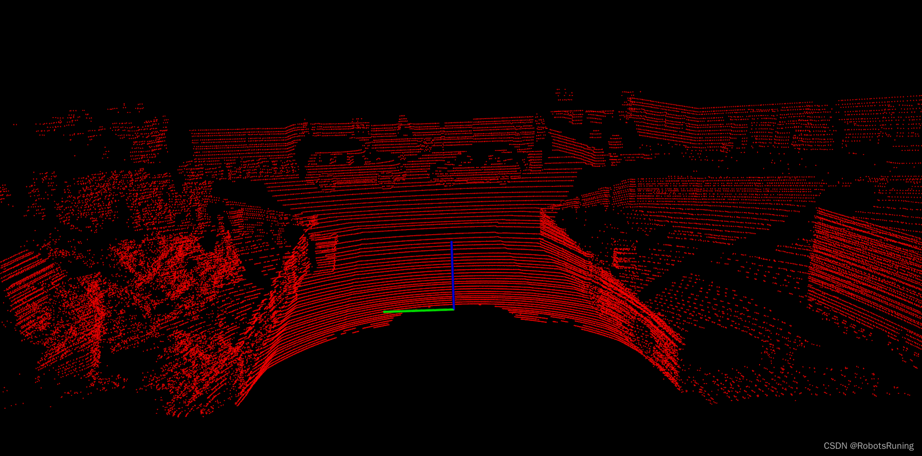
这里采用的是KITTI 05数据集第000396帧点云数据(bin 数据无法上传,如有需要自行下载)。
5. 结果

通过将Velodyne点云投影到相机图像上,我们可以将3D激光雷达数据与2D图像数据对齐。这对于许多应用非常有用,例如自动驾驶汽车中的目标检测和跟踪。该代码提供了一个基本的实现,演示了如何使用Eigen库和OpenCV库来执行这一任务。
致谢
GitHub - azureology/kitti-velo2cam: lidar to camera projection of KITTIlidar to camera projection of KITTI. Contribute to azureology/kitti-velo2cam development by creating an account on GitHub.![]() https://github.com/azureology/kitti-velo2cam
https://github.com/azureology/kitti-velo2cam


