电信运营商实战工程师系列文章.
思科设备篇-思科设备园区网实战.
文章目录
- 1. 思科设备链路捆绑实战
- 2. 思科设备VRRP、HSRP实战
- 3. 思科设备ACL实战全集
- 4. 思科设备RIP协议实战
- 5. 思科设备OSPF协议全集-理论
- 6. 思科设备OSPF协议全集-实战
1. 思科设备链路捆绑实战
知识点:
- 以太网链路捆绑的原理
- 二层接口捆绑的配置方法
- 负载及冗余测试
以太网链路捆绑的原理
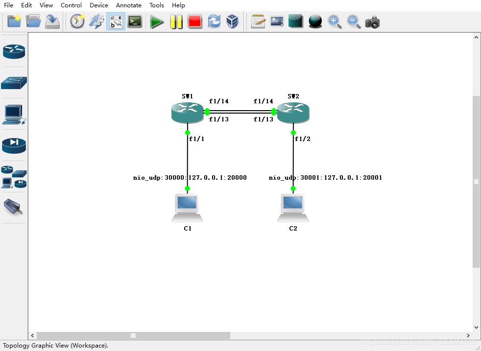
实验网络拓扑如下. SW1 和 SW2 是交换机,使用 c2691 插上 NM-16ESW 板卡模拟. C1 连接 SW1 的 fa1/1 口,C2 连接 SW2 的 fa1/2 口. SW1 和 SW2 的 fa1/13 和 fa1/14 同时互联.
SW1#conf t
Enter configuration commands, one per line.  End with CNTL/Z.
SW1(config)#no ip routing
SW2#conf t
Enter configuration commands, one per line.  End with CNTL/Z.
SW2(config)#no ip routing
SW1 和 SW2 之间有两条二层链路互联,这样就形成了二层环路. 当 C1 发送一个广播包,SW1 收到后会从一条链路(例如 fa1/13 口)发送给 SW2,而 SW2 又会从另一条链路(例如 fa1/14口)发送给 SW1. 这样广播包会在 SW1 和 SW2 之间无线循环,短时间二层网络就会大量充斥这个广播报文,使得网络瘫痪. 因而在现代交换机中都会运行生成树(spanning tree)协议,阻止二层环路的形成. 例如在上述网络拓扑中,生成树协议就会阻塞 fa1/14 接口,仅允许 fa1/13 口的链路连通.
查看接口信息,每个接口都是 100M. BW 100000 Kbit.
SW1#show interfaces
而我们的希望使用链路捆绑(或者称为链路聚合),让两条链路合并为一条链路,实现带宽翻倍,增强网络性能.
二层接口捆绑的配置方法
首先在 GNS3 模拟器上实验
配置 C1 和 C2 的 IP.
VPCS[1]> ip 192.168.1.10 24
Checking for duplicate address...
PC1 : 192.168.1.10 255.255.255.0

VPCS[1]> 2
VPCS[2]> ip 192.168.1.20 24
Checking for duplicate address...
PC2 : 192.168.1.20 255.255.255.0
此时 C1 和 C2 就能 ping 通了.
VPCS[2]> ping 192.168.1.10
192.168.1.10 icmp_seq=1 ttl=64 time=32.168 ms
192.168.1.10 icmp_seq=2 ttl=64 time=40.126 ms
192.168.1.10 icmp_seq=3 ttl=64 time=19.986 ms
192.168.1.10 icmp_seq=4 ttl=64 time=59.692 ms
192.168.1.10 icmp_seq=5 ttl=64 time=59.807 ms
进入系列接口 fa1/13 fa1/14
SW1(config)#int range fa1/13 -14
SW1(config-if-range)#
SW1(config-if-range)#channel-group ?
  <1-6>  Channel group number

SW1(config-if-range)#channel-group 1 mode ?
  on  Enable Etherchannel only
配置链路聚合. 将 fa1/13 和 fa1/14 聚合为 Port-channel1.
SW1(config-if-range)#channel-group 1 mode on
Creating a port-channel interface Port-channel1
SW2 上进行同样的配置.
SW2(config)#int range fa1/13 -1
SW2(config-if-range)#channel-group 1 mode on
查看接口信息. 产生了 Port-channel1.
SW1#show ip int b
Interface                  IP-Address      OK? Method Status                Protocol
FastEthernet0/0            unassigned      YES unset  administratively down down
FastEthernet0/1            unassigned      YES unset  administratively down down
FastEthernet1/0            unassigned      YES unset  up                    down
FastEthernet1/1            unassigned      YES unset  up                    up
FastEthernet1/2            unassigned      YES unset  up                    down
FastEthernet1/3            unassigned      YES unset  up                    down
FastEthernet1/4            unassigned      YES unset  up                    down
FastEthernet1/5            unassigned      YES unset  up                    down
FastEthernet1/6            unassigned      YES unset  up                    down
FastEthernet1/7            unassigned      YES unset  up                    down
FastEthernet1/8            unassigned      YES unset  up                    down
FastEthernet1/9            unassigned      YES unset  up                    down
FastEthernet1/10           unassigned      YES unset  up                    down
FastEthernet1/11           unassigned      YES unset  up                    down
FastEthernet1/12           unassigned      YES unset  up                    down
FastEthernet1/13           unassigned      YES unset  up                    up
FastEthernet1/14           unassigned      YES unset  up                    up
FastEthernet1/15           unassigned      YES unset  up                    down
Port-channel1              unassigned      YES unset  up                    up
Vlan1
查看 Port-channel1 的接口信息. BW 200000 Kbit 表示带宽为 200 M.
SW1#show int port-channel 1
Port-channel1 is up, line protocol is up
  Hardware is EtherChannel, address is c002.3f48.f10d (bia c002.3f48.f10d)
  MTU 1500 bytes, BW 200000 Kbit, DLY 1000 usec,
     reliability 255/255, txload 1/255, rxload 1/255
  Encapsulation ARPA, loopback not set
  Keepalive set (10 sec)
  Full-duplex, 100Mb/s
  Members in this channel: Fa1/13 Fa1/14
  ARP type: ARPA, ARP Timeout 04:00:00
  Last input never, output never, output hang never
  Last clearing of "show interface" counters never
  Input queue: 0/75/0/0 (size/max/drops/flushes); Total output drops: 0
  Queueing strategy: fifo
  Output queue: 0/40 (size/max)
  5 minute input rate 0 bits/sec, 0 packets/sec
  5 minute output rate 0 bits/sec, 0 packets/sec
     0 packets input, 0 bytes, 0 no buffer
     Received 0 broadcasts, 0 runts, 0 giants, 0 throttles
     0 input errors, 0 CRC, 0 frame, 0 overrun, 0 ignored
     0 input packets with dribble condition detected
     0 packets output, 0 bytes, 0 underruns
     0 output errors, 0 collisions, 1 interface resets
     0 babbles, 0 late collision, 0 deferred
     0 lost carrier, 0 no carrier
     0 output buffer failures, 0 output buffers swapped out
C2 连续 ping C1.
VPCS[2]> ping 192.168.1.10 -t
同时关闭 SW1 和 SW2 的 fa1/13 口.
SW1#conf t
Enter configuration commands, one per line.  End with CNTL/Z.
SW1(config)#int fa1/13
SW1(config-if)#shut
SW2#conf t
Enter configuration commands, one per line.  End with CNTL/Z.
SW2(config)#int fa1/13
SW2(config-if)#shut
在真实网络中会一直 ping 通. 由于模拟器的 BUG,会有短暂丢包.
接下来在 Cisco Packer Tracker 模拟器上实验.
使用 2 台 c2960 交换机 Switch0 和 Switch1. 它们之间有三条链路,分别连接它们的 fa0/1、fa0/2 和 fa0/3 口. PC0 连接 Switch0 的 fa0/10 口,PC1 连接 Switch1 的 fa0/10 口.

Cisco Packer Tracker 可以模拟思科交换机. 可以看到 Switch0 和 Switch1 之间只有 1 条链路连通,其余 2 条连接但未连通. 这是由于生成树协议阻塞了二层环路的形成.
配置 PC0 和 PC1 的 IP.


在 PC1 上 ping PC0.


进入 Switch0 的命令行控制页面.


进入特权模式
Switch0>enable
Switch0#
配置 fa0/1 - 3 接口.
Switch0#conf t
Enter configuration commands, one per line.  End with CNTL/Z.
Switch0(config)#int ran fa0/1 - 3
Switch(config-if-range)#
这个时候 mode 有 5 个选项.
Switch0(config-if-range)#channel-group 1 mode ?
  active     Enable LACP unconditionally
  auto       Enable PAgP only if a PAgP device is detected
  desirable  Enable PAgP unconditionally
  on         Enable Etherchannel only
  passive    Enable LACP only if a LACP device is detected
- 手动开启:
on LACP协议:一端active另一端active或passive可以协商成功;两端都是passive则不能成功.PAgP协议:一端auto另一端desirable可以协商成功;其它情况不成功.
配置链路聚合.
Switch0(config-if-range)#channel-group 1 mode on
在 Switch1 上配置链路聚合
Switch1>en
Switch#conf t
Enter configuration commands, one per line.  End with CNTL/Z.
Switch1(config)#int ran fa0/1 - 3
Switch1(config-if-range)#channel-group 1 mode on
此时,三条链路都开始工作,捆绑成一个链路.

在 PC1 上连续 ping PC0.

关闭 Switch0 的 fa0/1 口,模拟链路失效.
Switch0(config-if-range)#int fa0/1
Switch0(config-if)#shut
查看 Switch0 的连通情况.
Switch0#show etherchannel summary
Flags:  D - down        P - in port-channel
        I - stand-alone s - suspended
        H - Hot-standby (LACP only)
        R - Layer3      S - Layer2
        U - in use      f - failed to allocate aggregator
        u - unsuitable for bundling
        w - waiting to be aggregated
        d - default port


Number of channel-groups in use: 1
Number of aggregators:           1

Group  Port-channel  Protocol    Ports
------+-------------+-----------+----------------------------------------------

1      Po1(SU)           -      Fa0/1(D) Fa0/2(P) Fa0/3(P)
查看 Switch1 的连通情况.
Switch1#show etherchannel summary
Flags:  D - down        P - in port-channel
        I - stand-alone s - suspended
        H - Hot-standby (LACP only)
        R - Layer3      S - Layer2
        U - in use      f - failed to allocate aggregator
        u - unsuitable for bundling
        w - waiting to be aggregated
        d - default port


Number of channel-groups in use: 1
Number of aggregators:           1

Group  Port-channel  Protocol    Ports
------+-------------+-----------+----------------------------------------------

1      Po1(SU)           -      Fa0/1(D) Fa0/2(P) Fa0/3(P)
这个时候,聚合链路里只有 2 条实际链路. PC0 和 PC1 之间保持连通不会丢包.

关闭 Switch1 的 fa0/2 口.
Switch1(config)#int fa0/2
Switch1(config-if)#shut
查看 Switch0 的连通情况
Switch1#show etherchannel summary
Flags:  D - down        P - in port-channel
        I - stand-alone s - suspended
        H - Hot-standby (LACP only)
        R - Layer3      S - Layer2
        U - in use      f - failed to allocate aggregator
        u - unsuitable for bundling
        w - waiting to be aggregated
        d - default port


Number of channel-groups in use: 1
Number of aggregators:           1

Group  Port-channel  Protocol    Ports
------+-------------+-----------+----------------------------------------------

1      Po1(SU)           -      Fa0/1(D) Fa0/2(D) Fa0/3(P)
聚合链路里仅剩 1 条实际链路.

重新开启 fa0/1 和 fa0/2,聚合链路会自动加入这 2 个链路.
负载及冗余测试
查看聚合链路的负载方式.
Switch0#show etherchannel ?
  load-balance  Load-balance/frame-distribution scheme among ports in
                port-channel
  port-channel  Port-channel information
  summary       One-line summary per channel-group
  <cr>
Switch0#show etherchannel load-balance
EtherChannel Load-Balancing Operational State (src-mac):
Non-IP: Source MAC address
  IPv4: Source MAC address
  IPv6: Source MAC address
配置聚合链路的负载方式.
Switch0(config)#port-channel load-balance ?
  dst-ip       Dst IP Addr
  dst-mac      Dst Mac Addr
  src-dst-ip   Src XOR Dst IP Addr
  src-dst-mac  Src XOR Dst Mac Addr
  src-ip       Src IP Addr
  src-mac      Src Mac Addr
一般地,使用默认配置即可.
2. 思科设备VRRP、HSRP实战
知识点:
- VRRP/HSRP 的应用场景及工作原理
- VRRP/HSRP 的配置举例
- 运营商双组双备设计举例
- 流量倒换测试
虚拟路由器冗余协议(英语:Virtual Router Redundancy Protocol,缩写为 VRRP)是一种网络协议,可以为参与的路由器自动分配可用的IP地址。这个协议通过在子网中,自动选取默认网关,来增加路由的可用性和可靠性. 这个协议首先创建了一些虚拟路由器(这是对多个路由器的抽象),例如:主路由器、备路由器,这些路由器作为一个 group 协同工作。虚拟路由器被配置为默认网关,而不是物理路由器。当正在工作的物理路由器(代表着虚拟路由器)发生故障时,另一个物理路由器会自动被选举出来替代它。特定时间内正在转发数据包的物理路由器被称为主路由器。 VRRP提供了路由器状态的信息,而不是该路由器的数据包处理、交换的信息。每一个VRRP实例被限制到单一子网内。它不会参与子网外的IP路由,也不会以任何方式影响路由表。VRRP可以通过IPv4或者IPv6(三层IP网),运行在Ethernet(以太网)、MPLS和令牌环网络(二层链路网)。该协议在IETF(Internet Engineering Task Force)的RFC 5798发布,这是一个开放标准.
热备份路由器协议(英语:Hot Standby Router Protocol,缩写为 HSRP),一种由思科公司发展的专有网络协议,拥有美国专利第5,473,599号,定义于 RFC 2281. HSRP 与 VRRP 在工作原理上本质相同,区别是 HSRP 是思科专有协议受到专利保护. 当主要的网关失效时,可以利用这个协议,进行故障移转(failover),让备援的网关运行原有网关的功能,以保持默认网关(default gateway)的功能正常。
