Packet Tracer - 配置Cisco路由器以实现Syslog、NTP和SSH功能
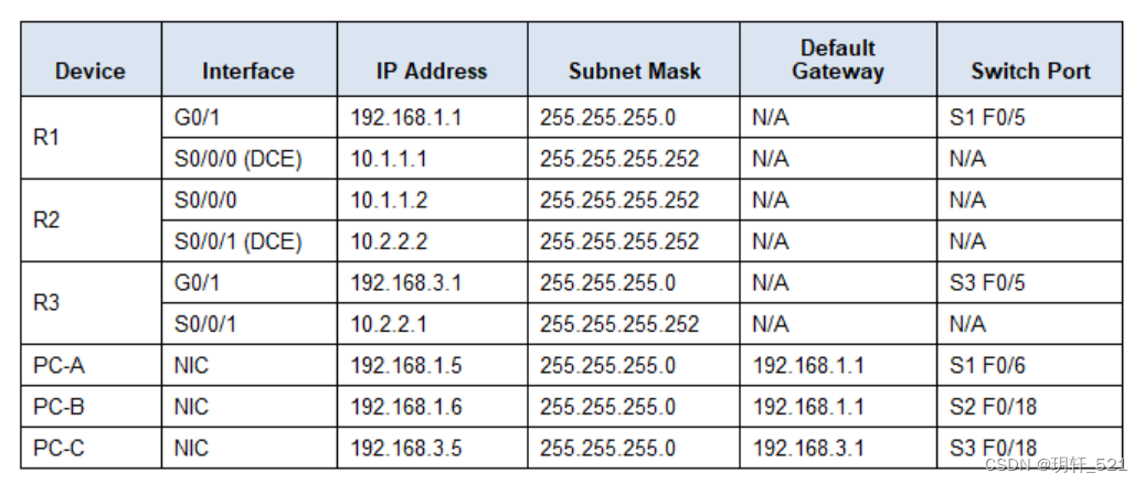
地址表
目标:
- 配置OSPF MD5身份验证。
- 配置NTP服务。
- 设置路由器将消息记录到syslog服务器。
- 配置R3路由器以支持SSH连接。
背景/场景:
在本练习中,您将配置OSPF MD5身份验证以实现安全的路由更新。
NTP服务器是本次活动中主NTP服务器。您需要在NTP服务器和路由器上配置身份验证,并设置路由器允许软件时钟通过NTP与时间服务器同步。同时,您还需要配置路由器定期使用从NTP获取的时间更新硬件时钟。
Syslog服务器在此活动提供消息记录功能。您需要配置路由器识别接收日志消息的远程主机(即Syslog服务器)。
您需要在路由器上配置时间戳服务以便于记录日志。在使用Syslog监控网络时,在Syslog消息中显示正确的日期和时间至关重要。
此外,您还将配置R3路由器,使其能够通过SSH而非Telnet进行安全管理。服务器已经预先配置好了相应的NTP和Syslog服务,NTP无需身份验证。路由器已预设了以下密码:
启用密码:ciscoenpa55
vty线路密码:ciscovtypa55
注意:请注意,在开发本活动所使用的Packet Tracer版本(v6.2)中,MD5是最强支持的加密方式。虽然MD5存在已知的安全漏洞,但在实际操作中应根据组织的安全需求选择合适的加密方法。在本活动中,安全要求指定使用MD5加密。
第一部分:配置OSPF MD5身份验证
步骤1:测试连通性。所有设备应能成功ping通所有其他IP地址。
步骤2:为区域0内的所有路由器配置OSPF MD5身份验证。
针对区域0中的所有路由器设置OSPF MD5身份验证:
R1(config)# router ospf 1
R1(config-router)# area 0 authentication message-digest
R2(config)#router ospf 1
R2(config-router)#area 0 authentication message-digest
R3(config)#router ospf 1
R3(config-router)#area 0 authentication message-digest
步骤3:为区域0内的所有路由器配置MD5密钥。
在R1、R2和R3的串行接口上配置MD5密钥,对密钥1使用密码MD5pa55。
R1(config)# interface s0/0/0
R1(config-if)# ip ospf message-digest-key 1 md5 MD5pa55
R2(config)#interface Serial0/0/0
R2(config-if)#ip ospf message-digest-key 1 md5 MD5pa55
R2(config)#interface Serial0/0/1
R2(config-if)#ip ospf message-digest-key 1 md5 MD5pa55
R3(config)#interface Serial0/0/1
R3(config-if)#ip ospf message-digest-key 1 md5 MD5pa55
步骤4:验证配置。
a. 使用命令show ip ospf interface 验证MD5身份验证配置是否正确生效。
b. 验证端到端的连通性,确保网络连接无误。
第二部分:配置NTP
步骤1:在PC-A上启用NTP身份验证。
a. 在PC-A上,点击服务标签下的“NTP”以确认NTP服务已启用。
b. 为配置NTP身份验证,请点击“认证”下的“启用”。使用密钥1和密码NTPpa55进行身份验证。

步骤2:将R1、R2和R3配置为NTP客户端。
R1(config)#ntp server 192.168.1.5 key 1
R2(config)#ntp server 192.168.1.5 key 1
R3(config)#ntp server 192.168.1.5 key 1
通过执行命令show ntp status来验证客户端配置是否正确。
步骤3:配置路由器定期更新硬件时钟。
设置R1、R2和R3路由器定期从NTP同步的时间更新硬件时钟。
R1(config)#ntp update-calendar
R2(config)#ntp update-calendar
R3(config)#ntp update-calendar
退出全局配置模式,并使用命令show clock来验证硬件时钟是否已成功更新。
步骤4:在路由器上配置NTP身份验证。
在R1、R2和R3上使用密钥1和密码NTPpa55配置NTP身份验证。
R1(config)# ntp authenticate
R1(config)# ntp trusted-key 1
R1(config)# ntp authentication-key 1 md5 NTPpa55
R2(config)# ntp authenticate
R2(config)# ntp trusted-key 1
R2(config)# ntp authentication-key 1 md5 NTPpa55
R3(config)# ntp authenticate
R3(config)# ntp trusted-key 1
R3(config)# ntp authentication-key 1 md5 NTPpa55
步骤5:配置路由器对日志消息添加时间戳。
在路由器上配置日志记录的时间戳服务。
R1(config)#service timestamps log datetime msec
R2(config)#service timestamps log datetime msec
R3(config)#service timestamps log datetime msec
第三部分:配置路由器将消息记录到Syslog服务器
步骤1:配置路由器以识别接收日志消息的远程主机(即Syslog服务器)。
路由器控制台将会显示一条消息,表明已经开始记录日志。
R1(config)#logging 192.168.1.6
R2(config)#logging 192.168.1.6
R3(config)#logging 192.168.1.6
步骤2:验证日志配置。
使用命令show logging来验证是否已启用日志记录功能。
步骤3:检查Syslog服务器的日志记录。
在Syslog服务器对话框的服务标签下,选择“Syslog服务”按钮。观察从路由器接收到的日志消息。
注意:通过在路由器上执行命令可以生成服务器上的日志消息。例如,进入和退出全局配置模式会生成一个信息性配置消息。您可能需要点击其他服务,然后再点击Syslog以刷新消息显示界面。
第四部分:配置R3以支持SSH连接
步骤1:配置域名
在R3上配置一个域名ccnasecurity.com。
R3(config)#ip domain-name ccnasecurity.com
步骤2:配置R3上SSH服务器的登录用户
创建一个用户名为SSHadmin,具有最高权限级别的用户ID,并设置秘密密码为ciscosshpa55。
R3(config)# username SSHadmin privilege 15 secret ciscosshpa55
步骤3:配置R3上的入站vty线路
要求使用本地用户账户进行强制登录和验证,只接受SSH连接。
R3(config)#line vty 0 4
R3(config-line)# login local
R3(config-line)# transport input ssh
步骤4:删除R3上的现有密钥对
如有任何现有的RSA密钥对,应在路由器上将其删除。
R3(config)#crypto key zeroize rsa
注:如果不存在任何密钥,您可能会收到此消息:% No Signature RSA Keys found in configuration.
步骤5:为R3生成RSA加密密钥对
路由器使用RSA密钥对进行SSH传输数据的身份验证和加密。配置RSA密钥时,选择模数为1024(默认值为512,范围为360至2048)。
R3(config)# crypto key generate rsa
The name for the keys will be: R3.ccnasecurity.com
Choose the size of the key modulus in the range of 360 to 2048 for your
General Purpose Keys. Choosing a key modulus greater than 512 may take
a few minutes.

How many bits in the modulus [512]: 1024
% Generating 1024 bit RSA keys, keys will be non-exportable...[OK]
注:在Packet Tracer中为R3生成RSA加密密钥对的命令与实验室中的有所不同。
步骤6:验证SSH配置
使用show ip ssh命令查看当前设置,确保身份验证超时和重试次数保持默认值120和3。
步骤7:配置SSH超时和认证参数
可以更改默认的SSH超时和认证参数使其更加严格。将超时时间设置为90秒,认证重试次数设为2次,版本设为2。
R3(config)#ip ssh version 2
R3(config)#ip ssh authentication-retries 2
R3(config)#ip ssh time-out 90
再次执行show ip ssh命令确认这些值已更改。
步骤8:尝试从PC-C通过Telnet连接到R3
打开PC-C的桌面,选择“命令提示符”图标。从PC-C输入命令通过Telnet连接到R3。
PC> telnet 192.168.3.1
此连接应失败,因为R3已被配置为仅在其虚拟终端线上接受SSH连接。
步骤9:通过SSH从PC-C连接到R3
打开PC-C的桌面,选择“命令提示符”图标。从PC-C输入命令通过SSH连接到R3。当提示输入密码时,请输入为管理员账户配置的密码ciscosshpa55。
PC> ssh -l SSHadmin 192.168.3.1
步骤10:通过R2使用SSH连接到R3
为了对R3进行故障排查和维护,ISP的管理员必须使用SSH访问路由器CLI。在R2的CLI中,输入命令通过SSH版本2使用SSHadmin用户账户连接到R3。当提示输入密码时,请输入为管理员配置的密码ciscosshpa55。
R2# ssh -v 2 -l SSHadmin 10.2.2.1
步骤11:检查结果
您的完成百分比应为100%。点击“检查结果”以查看反馈信息和已完成所需组件的验证情况。
实验脚本:
# PART1
R1:
router ospf 1
area 0 authentication message-digest
interface Serial0/0/0
ip ospf message-digest-key 1 md5 MD5pa55

R2:
router ospf 1
area 0 authentication message-digest
interface Serial0/0/0
ip ospf message-digest-key 1 md5 MD5pa55
interface Serial0/0/1
ip ospf message-digest-key 1 md5 MD5pa55

R3:
router ospf 1
area 0 authentication message-digest
interface Serial0/0/1
ip ospf message-digest-key 1 md5 MD5pa55

# PART2
# 打开NTP服务器,配置NTP服务。
R1:
ntp authentication-key 1 md5 NTPpa55
ntp authenticate
ntp trusted-key 1
ntp server 192.168.1.5 key 1
ntp update-calendar
service timestamps log datetime msec

R2:
ntp authentication-key 1 md5 NTPpa55
ntp authenticate
ntp trusted-key 1
ntp server 192.168.1.5 key 1
ntp update-calendar
service timestamps log datetime msec

R3:
ntp authentication-key 1 md5 NTPpa55
ntp authenticate
ntp trusted-key 1
ntp server 192.168.1.5 key 1
ntp update-calendar
service timestamps log datetime msec


# PART3
R1:
logging 192.168.1.6
R2:
logging 192.168.1.6
R3:
logging 192.168.1.6

# PART4
R3:
ip ssh version 2
ip ssh authentication-retries 2
ip ssh time-out 90
ip domain-name ccnasecurity.com
username SSHadmin privilege 15 secret ciscosshpa55
crypto key zeroize rsa

crypto key generate rsa

line vty 0 4
 login local
 transport input ssh
