文章目录
- 一、串口通信
- 二、UART通信
- 三、tx发送模块
- 四、rx模块接收
一、串口通信
处理器与外部设备通信的两种方式:
串行通信: 指数据的各个位使用多条数据线同时进行传输。
并行通信: 将数据分成一位一位的形式在一条数据线上逐个传输。

串行通信的通信方式:
同步通信: 带时钟同步信号的数据传输,发送方和接收方在同一时钟控制下,同步传输数据。
异步通信: 不带时钟同步信号的数据传输,发送方和接收方使用各自的时钟控制数据的发送和接收过程。
串行通信的传输方向:
单工: 数据只能沿一个方向进行传输。
半双工: 数据传输可以沿两个方向,但需要分时进行。
全双工: 数据可以同时进行双向传输。

常见的串行通信接口:
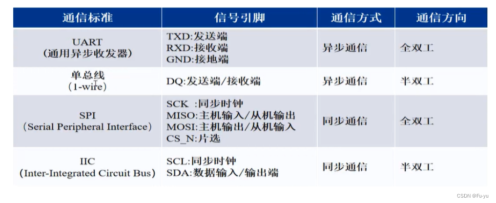
二、UART通信
通用异步收发传输器(Universal Asynchronous Receiver/Transmitter),通常称作UART,是一种异步收发传输器。 它在发送数据时将并行数据转换为串行的数据来传输,在接收数据时将接收到的串行数据转换成并行数据。UART串口通信需要两根信号线来实现,一根用于发送,另一个用于接收。

协议层:
数据格式,1帧数据由4部分组成。
- 起始位(1bit)
- 数据位(6/7/8bit)
- 奇偶校验位(1bit)
- 停止位(1bit/1.5bit/2bit)

奇校验:原始码流+校验位 总共有奇数个1
偶校验:原始码流+校验位 总共有偶数个1
传输速率:
串口通信速率用波特率表示,它表示每秒传输二进制数据的位数,单位是bit/s(位/秒),简称bps;常用的波特率有9600,115200等。
物理层:
串口电平标准:
- TTL电平的串口(3.3V)
- RS232电平的串口(+5V ~ +12V为低电平,-12V ~ -5V为高电平)
三、tx发送模块
tx发送模块:共四个状态,IDLE状态,START状态,DATA状态,FINISH状态。
/*
 * @Description: tx输出,波特率115200,系统时钟50M,传输1bit所需计数434个周期
 * @Author: Fu Yu
 * @Date: 2023-08-15 11:10:41
 * @LastEditTime: 2023-08-15 14:55:04
 * @LastEditors: Fu Yu
 */

module uart_tx (
    input           wire                clk         ,
    input           wire                rst_n       ,
    input           wire [7:0]          tx_din      ,
    input           wire                tx_din_vld  ,

    output          wire                tx_dout     ,
    output          wire                ready
);

parameter MAX_BIT = 50_000_000/115200;//1bit计数最大值,434

localparam  IDLE   = 4'b0001,
            START  = 4'b0010,
            DATA   = 4'b0100,
            FINISH = 4'b1000;

reg [3:0]   state_c;//现态
reg [3:0]   state_n;//次态

wire        idle_start  ;// IDLE -> START
wire        start_data  ;// START -> DATA
wire        data_finish ;// DATA -> FINISH
wire        finish_idle ;// FINFISH -> IDLE

reg			[8:0]	cnt_bit	   	;
wire				add_cnt_bit	;
wire				end_cnt_bit	;

reg			[11:0]	cnt_data	   	;
wire				add_cnt_data	;
wire				end_cnt_data	;

reg [7:0]   tx_din_r;
reg         tx_dout_r;

//****************************************************************
//--                状态机
//****************************************************************
always @(posedge clk or negedge rst_n) begin
    if(!rst_n) begin
        state_c <= IDLE;
    end
    else begin
        state_c <= state_n;
    end
end

always @( *) begin
    case (state_c)
        IDLE : begin
            if(idle_start) begin
                state_n = START;
            end
            else begin
                state_n = state_c;
            end
        end

        START : begin
            if(start_data) begin
                state_n = DATA;
            end
            else begin
                state_n = state_c;
            end
        end

        DATA : begin
            if(data_finish) begin
                state_n = FINISH;
            end
            else begin
                state_n = state_c;
            end
        end

        FINISH : begin
            if(finish_idle) begin
                state_n = IDLE;
            end
            else begin
                state_n = state_c;
            end
        end

        default : state_n = IDLE;

    endcase
end


assign idle_start  = state_c == IDLE && tx_din_vld ;
assign start_data  = state_c == START &&  end_cnt_bit;
assign data_finish = state_c == DATA &&  end_cnt_data;
assign finish_idle = state_c == FINISH && end_cnt_bit;

//****************************************************************
//--                    计数器
//****************************************************************
//1bit计数器
always @(posedge clk or negedge rst_n)begin
   if(!rst_n)begin
        cnt_bit <= 'd0;
    end
    else if(add_cnt_bit)begin
        if(end_cnt_bit)begin
            cnt_bit <= 'd0;
        end
        else begin
            cnt_bit <= cnt_bit + 1'b1;
        end
    end
end

assign add_cnt_bit = state_c == START || state_c == FINISH || state_c == DATA;
assign end_cnt_bit = add_cnt_bit && cnt_bit == MAX_BIT - 1;

//8bit计数器
always @(posedge clk or negedge rst_n)begin
   if(!rst_n)begin
        cnt_data <= 'd0;
    end
    else if(add_cnt_data)begin
        if(end_cnt_data)begin
            cnt_data <= 'd0;
        end
        else begin
            cnt_data <= cnt_data + 1'b1;
        end
    end
end

assign add_cnt_data = state_c == DATA && end_cnt_bit;
assign end_cnt_data = add_cnt_data && cnt_data == 8 - 1 ;


//****************************************************************
//--                输入数据寄存
//****************************************************************
always @(posedge clk or negedge rst_n) begin
    if(!rst_n) begin
        tx_din_r <= 0;
    end
    else begin
        tx_din_r <= tx_din;
    end
end


//****************************************************************
//--            实现串口时序
//****************************************************************
always @( *) begin
    case (state_c)
        IDLE : begin
            tx_dout_r = 1;
        end

        START : begin
            tx_dout_r = 0;
        end

        DATA : begin
            if(tx_din_r[cnt_data]) begin
                tx_dout_r = 1;
            end
            else begin
                tx_dout_r = 0;
            end
        end

        FINISH : begin
            tx_dout_r = 1;
        end

        default : tx_dout_r = 1;
    endcase
end

assign tx_dout = tx_dout_r;

assign ready = state_c == IDLE;


endmodule //uart_tx
测试文件:
/*
 * @Description: uart_tx仿真模块
 * @Author: Fu Yu
 * @Date: 2023-08-15 14:58:32
 * @LastEditTime: 2023-08-15 15:06:49
 * @LastEditors: Fu Yu
 */


`timescale 1ns/1ns

module tb_uart_tx();

//激励信号定义
    reg				tb_clk  	;
    reg				tb_rst_n	;
    reg		[7:0]   tb_tx_din	;
    reg             tb_tx_din_vld;

//输出信号定义
    wire			tx_dout	;
    wire			ready    ;

//时钟周期参数定义
    parameter		CLOCK_CYCLE = 20;
    defparam  u_uart_tx.MAX_BIT = 10;
//模块例化
uart_tx u_uart_tx(
   /*input           wire       */  .       clk       (tb_clk)  ,
   /*input           wire       */  .       rst_n     (tb_rst_n)  ,
   /*input           wire [7:0] */  .       tx_din    (tb_tx_din) ,
   /*input           wire       */  .       tx_din_vld(tb_tx_din_vld) ,
   /*output          wire       */  .       tx_dout   (tx_dout)  ,
   /*output          wire       */  .       ready     (ready)
);

//产生时钟
    initial 		tb_clk = 1'b0;
    always #(CLOCK_CYCLE/2) tb_clk = ~tb_clk;

//产生激励
    initial  begin
        tb_rst_n = 1'b1;
        tb_tx_din = 0;
        tb_tx_din_vld = 0;
        #(CLOCK_CYCLE*2);
        tb_rst_n = 1'b0;
        #(CLOCK_CYCLE*20);
        tb_rst_n = 1'b1;


        repeat(10) begin
            tb_tx_din_vld = 1;
            tb_tx_din = {$random};
            #20;
            tb_tx_din_vld = 0;
            wait(ready == 1);
            #20;
        end

        #1000;
        $stop;
    end

endmodule
仿真波形图:
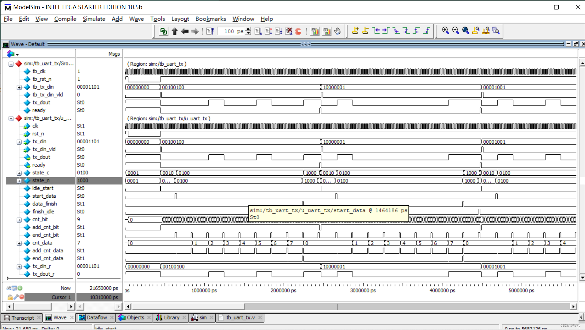
上板验证:
加入按键控制模块,每一次按下,输出8’hAB
按键消抖模块:
/*
 * @Description: 按键消抖,使用延迟方法,消抖后输出高电平信号
 * @Author: Fu Yu
 * @Date: 2023-08-07 14:22:56
 * @LastEditTime: 2023-08-07 14:48:48
 * @LastEditors: Fu Yu
 */


module key_filter #(
    parameter WITDH = 3//WITDH表示位宽
)(
    input       wire                clk         ,
    input       wire                rst_n       ,

    input       wire [WITDH-1:0]    key_in      ,

    output      wire [WITDH-1:0]    key_down
);

parameter MAX_20MA = 20'd999_999;//20ms

reg [WITDH - 1:0]   key_r0;//同步信号
reg [WITDH - 1:0]   key_r1;//打拍
reg [WITDH - 1:0]   key_r2;
reg [WITDH - 1:0]   key_down_r;
reg [19:0]          cnt_20ms;
reg                 flag;//开始计数信号

wire [WITDH - 1:0]  nedge;//下降沿
wire add_cnt_20ms;
wire end_cnt_20ms;


//****************************************************************
//--同步,打拍
//****************************************************************
always @(posedge clk or negedge rst_n) begin
    if(!rst_n) begin
        key_r0 <= {WITDH{1'b1}};
        key_r1 <= {WITDH{1'b1}};
        key_r2 <= {WITDH{1'b1}};
    end
    else begin
        key_r0 <= key_in;
        key_r1 <= key_r0;
        key_r2 <= key_r1;
    end
end

//下降沿检测
assign nedge = ~key_r1 & key_r2;


//****************************************************************
//--flag
//****************************************************************
always @(posedge clk or negedge rst_n) begin
    if(!rst_n) begin
        flag <= 1'b0;
    end
    else if(nedge) begin//检测到下降沿开始计数
        flag <= 1'b1;
    end
    else if(end_cnt_20ms) begin//20ms后停止计数
        flag <= 1'b0;
    end
    else begin
        flag <= flag;
    end
end


//****************************************************************
//--20ms计数器
//****************************************************************


always @(posedge clk or negedge rst_n)begin
   if(!rst_n)begin
        cnt_20ms <= 20'd0;
    end
    else if(add_cnt_20ms)begin
        if(end_cnt_20ms)begin
            cnt_20ms <= 20'd0;
        end
        else begin
            cnt_20ms <= cnt_20ms + 1'b1;
        end
    end
end

assign add_cnt_20ms = flag;
assign end_cnt_20ms = add_cnt_20ms && cnt_20ms == MAX_20MA;

//****************************************************************
//--key_down
//****************************************************************
always @(posedge clk or negedge rst_n) begin
    if(!rst_n) begin
        key_down_r <= {WITDH{1'b0}};
    end
    else if(end_cnt_20ms) begin
        key_down_r <= ~key_r2;
    end
    else begin
        key_down_r <= {WITDH{1'b0}};
    end
end

assign key_down = key_down_r;

endmodule //key_filter
顶层模块:
module top (
    input           wire            clk         ,
    input           wire            rst_n       ,
    input           wire            key_in      ,

    output          wire            tx
);


wire        key_wire;
wire        ready;


key_filter #(.WITDH(1)) u_key_filter(
   /* input       wire            */.   clk     (clk)    ,
   /* input       wire            */.   rst_n   (rst_n)    ,
   /* input       wire [WITDH-1:0]*/.   key_in  (key_in)    ,
   /* output      wire [WITDH-1:0]*/.   key_down(key_wire)
);

uart_tx u_uart_tx(
   /*input           wire       */  .       clk       (clk)  ,
   /*input           wire       */  .       rst_n     (rst_n)  ,
   /*input           wire [7:0] */  .       tx_din    (8'hab)  ,
   /*input           wire       */  .       tx_din_vld(key_wire && ready)  ,
   /*output          wire       */  .       tx_dout   (tx)  ,
   /*output          wire       */  .       ready     (ready)
);


endmodule //top
效果展示:
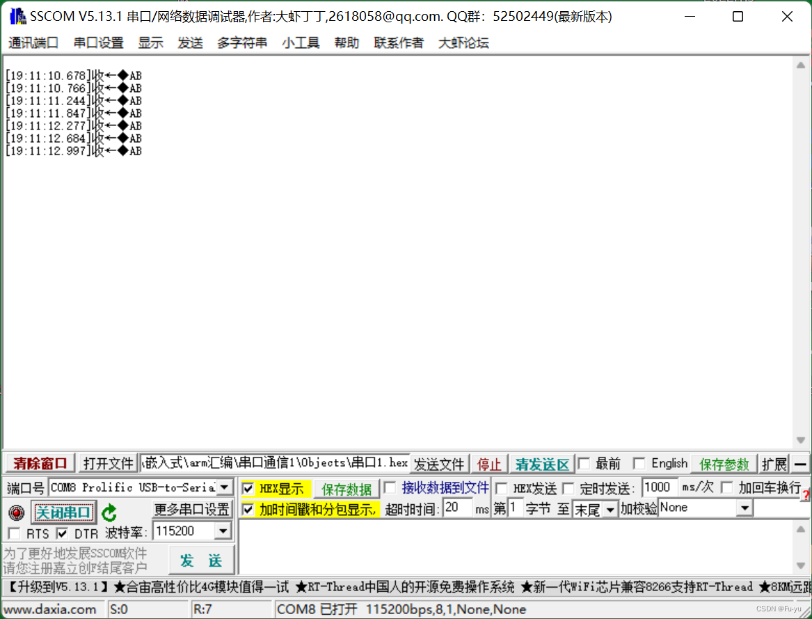
四、rx模块接收
/*
 * @Description: rx接收,波特率115200,系统时钟50M,传输1bit所需计数434个周期
 * @Author: Fu Yu
 * @Date: 2023-08-15 11:10:41
 * @LastEditTime: 2023-08-16 10:03:27
 * @LastEditors: Fu Yu
 */

module uart_rx (
    input           wire                clk         ,
    input           wire                rst_n       ,
    input           wire                rx_din       ,

    output          wire [7:0]          rx_dout      ,
    output          wire                rx_dout_vld  ,
    output          wire                ready
);

parameter MAX_BIT = 50_000_000/115200;//1bit计数最大值,434

localparam  IDLE   = 4'b0001,
            START  = 4'b0010,
            DATA   = 4'b0100,
            FINISH = 4'b1000;

reg [3:0]   state_c;//现态
reg [3:0]   state_n;//次态

wire        idle_start  ;// IDLE -> START
wire        start_data  ;// START -> DATA
wire        data_finish ;// DATA -> FINISH
wire        finish_idle ;// FINFISH -> IDLE

reg			[8:0]	cnt_bit	   	;
wire				add_cnt_bit	;
wire				end_cnt_bit	;

reg			[11:0]	cnt_data	   	;
wire				add_cnt_data	;
wire				end_cnt_data	;

reg     [7:0]       rx_dout_r;

//****************************************************************
//--                状态机
//****************************************************************
always @(posedge clk or negedge rst_n) begin
    if(!rst_n) begin
        state_c <= IDLE;
    end
    else begin
        state_c <= state_n;
    end
end

always @( *) begin
    case (state_c)
        IDLE : begin
            if(idle_start) begin
                state_n = START;
            end
            else begin
                state_n = state_c;
            end
        end

        START : begin
            if(start_data) begin
                state_n = DATA;
            end
            else begin
                state_n = state_c;
            end
        end

        DATA : begin
            if(data_finish) begin
                state_n = FINISH;
            end
            else begin
                state_n = state_c;
            end
        end

        FINISH : begin
            if(finish_idle) begin
                state_n = IDLE;
            end
            else begin
                state_n = state_c;
            end
        end

        default : state_n = IDLE;

    endcase
end


assign idle_start  = state_c == IDLE && rx_din == 0 ;
assign start_data  = state_c == START &&  end_cnt_bit;
assign data_finish = state_c == DATA &&  end_cnt_data;
assign finish_idle = state_c == FINISH && end_cnt_bit;

//****************************************************************
//--                    计数器
//****************************************************************
//1bit计数器
always @(posedge clk or negedge rst_n)begin
   if(!rst_n)begin
        cnt_bit <= 'd0;
    end
    else if(add_cnt_bit)begin
        if(end_cnt_bit)begin
            cnt_bit <= 'd0;
        end
        else begin
            cnt_bit <= cnt_bit + 1'b1;
        end
    end
end

assign add_cnt_bit = state_c == START || state_c == FINISH || state_c == DATA;
assign end_cnt_bit = add_cnt_bit && cnt_bit == MAX_BIT - 1;

//8bit计数器
always @(posedge clk or negedge rst_n)begin
   if(!rst_n)begin
        cnt_data <= 'd0;
    end
    else if(add_cnt_data)begin
        if(end_cnt_data)begin
            cnt_data <= 'd0;
        end
        else begin
            cnt_data <= cnt_data + 1'b1;
        end
    end
end

assign add_cnt_data = state_c == DATA && end_cnt_bit;
assign end_cnt_data = add_cnt_data && cnt_data == 8 - 1 ;


//****************************************************************
//--            实现数据接收
//****************************************************************
always @(posedge clk or negedge rst_n) begin
    if(!rst_n) begin
        rx_dout_r <= 0;
    end
    else if(state_c == DATA && cnt_bit == MAX_BIT >> 1) begin
        rx_dout_r[cnt_data] <= rx_din;
    end
end

assign rx_dout = rx_dout_r;

assign rx_dout_vld = data_finish;

assign ready = state_c == IDLE;


endmodule //uart_rx
ip核fifo调用:
module ctrl (
    input           wire            clk                 ,
    input           wire            rst_n               ,
    input           wire [7:0]      rx_data             ,
    input           wire            rx_data_vld         ,
    input           wire            tx_ready            ,

    output          wire [7:0]      tx_data             ,
    output          wire            tx_data_vld
);


wire  fifo_rd_empty;
wire  fifo_wr_full;


fifo	fifo_inst (
	.aclr ( ~rst_n ),

	.data ( rx_data ),
	.wrclk ( clk ),
	.wrreq ( rx_data_vld && ~fifo_wr_full ),

	.q ( tx_data ),
    .rdclk ( clk ),
	.rdreq ( tx_ready && ~fifo_rd_empty ),

	.rdempty ( fifo_rd_empty ),
	.wrfull ( fifo_wr_full )
	);


assign tx_data_vld = tx_ready && ~fifo_rd_empty ;

endmodule //ctrl
顶层模块:
module top (
    input           wire            clk         ,
    input           wire            rst_n       ,
    input           wire            key_in      ,
    input           wire            rx          ,

    output          wire            tx
);


wire        key_wire;
wire        tx_ready;
wire [7:0]  rx_data;
wire        rx_data_vld;
wire [7:0]  tx_data;
wire        tx_data_vld;


key_filter #(.WITDH(1)) u_key_filter(
   /* input       wire            */.   clk     (clk)    ,
   /* input       wire            */.   rst_n   (rst_n)    ,
   /* input       wire [WITDH-1:0]*/.   key_in  (key_in)    ,
   /* output      wire [WITDH-1:0]*/.   key_down(key_wire)
);

uart_tx u_uart_tx(
   /*input           wire       */  .       clk       (clk)  ,
   /*input           wire       */  .       rst_n     (rst_n)  ,
   /*input           wire [7:0] */  .       tx_din    (tx_data)  ,
   /*input           wire       */  .       tx_din_vld(tx_data_vld)  ,

   /*output          wire       */  .       tx_dout   (tx)  ,
   /*output          wire       */  .       ready     (tx_ready)
);


uart_rx u_uart_rx(
   /* input           wire       */.         clk        (clk ) ,
   /* input           wire       */.         rst_n      (rst_n ) ,
   /* input           wire       */.         rx_din     (rx )  ,

   /* output          wire [7:0] */.         rx_dout    (rx_data)  ,
   /* output          wire       */.         rx_dout_vld(rx_data_vld)  ,
   /* output          wire       */.         ready      ()
);


ctrl  u_ctrl(
    /* input           wire         */ .   clk        (clk) ,
    /* input           wire         */ .   rst_n      (rst_n) ,
    /* input           wire [7:0]   */ .   rx_data    (rx_data) ,
    /* input           wire         */ .   rx_data_vld(rx_data_vld) ,
    /* input           wire         */ .   tx_ready   (tx_ready) ,

    /* output          wire [7:0]   */ .   tx_data    (tx_data) ,
    /* output          wire         */ .   tx_data_vld(tx_data_vld)
);


endmodule //top
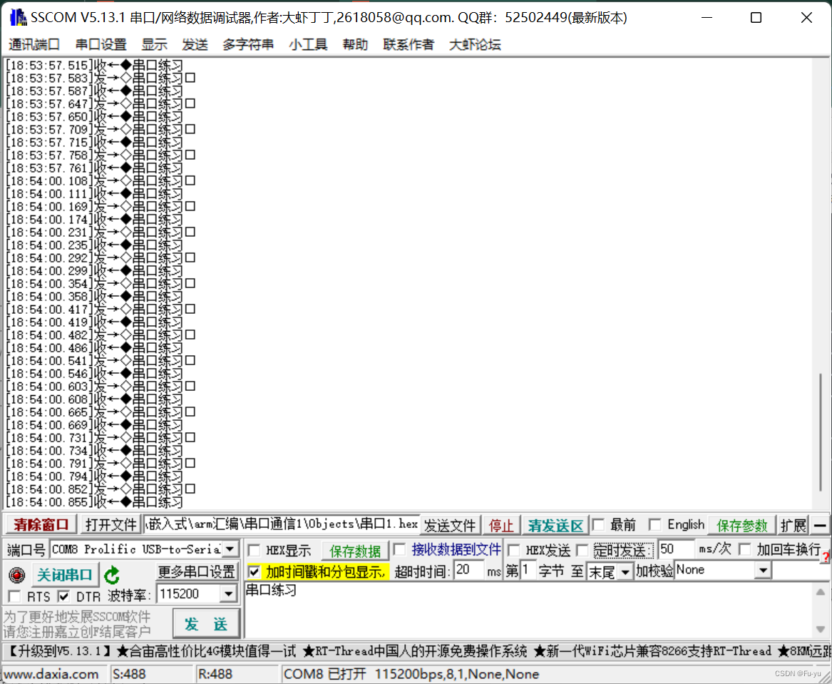
将rx接收模块与tx发送模块联合使用,效果如下:
