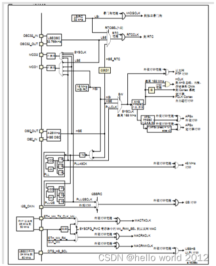
1.0 时钟系统框图
1.1 时钟系统知识
1. STM32 有5个时钟源:HSI、HSE、LSI、LSE、PLL。
①、HSI是高速内部时钟,RC振荡器,频率为16MHz,精度不高。可以直接作为系统
时钟或者用作PLL时钟输入。
②、HSE是高速外部时钟,可接石英/陶瓷谐振器,或者接外部时
钟源,频率范围为4MHz~26MHz。
③、LSI是低速内部时钟,RC振荡器,频率为32kHz,提供低功耗时钟。主要供独立看 门狗和自动唤醒单元使用。
④、LSE是低速外部时钟,接频率为32.768kHz的石英晶体。RTC
⑤、PLL为锁相环倍频输出。STM32F4有两个PLL:
主
PLL(PLL)
由
HSE
或者
HSI
提供时钟信号,并具有两个不同的输出时钟。
第一个输出PLLP用于生成高速的系统时钟(最高
168MHz
)
第二个输出PLLQ用于生成
USB OTG FS
的时钟(
48MHz),随机数发生器的时钟和SDIO
时钟。
专用PLL(PLLI2S)
用于生成精确时钟,从而在
I2S
接口实现高品质音频性能。
2. 系统时钟SYSCLK可来源于三个时钟源:
①、HSI振荡器时钟
②、HSE振荡器时钟
③、PLL时钟
3.STM32F4时钟信号输出MCO1(PA8)和MCO2(PC9)。
MCO1:
用户可以配置预分频器(
1~5
)向
MCO1
引脚
PA8
输出
4
个不同的时钟源:
HIS
LSE
HSE
PLL
MCO2:
用户可以配置预分频器(
1~5
)向
MCO2
引脚
PC9
输出
4
个不同的时钟源:
HSE
PLL
SYSCLK
PLLI2S
MCO最大输出时钟不超过100MHz
4.任何一个外设在使用之前,必须首先使能其相应的时钟。
1.2 RCC相关配置寄存器
typedef struct
{
  __IO uint32_t CR;
  __IO uint32_t PLLCFGR;
  __IO uint32_t CFGR;          /*!< RCC clock configuration register,                            Address offset: 0x08 */
  __IO uint32_t CIR;           /*!< RCC clock interrupt register,                                Address offset: 0x0C */
  __IO uint32_t AHB1RSTR;      /*!< RCC AHB1 peripheral reset register,                          Address offset: 0x10 */
  __IO uint32_t AHB2RSTR;      /*!< RCC AHB2 peripheral reset register,                          Address offset: 0x14 */
  __IO uint32_t AHB3RSTR;      /*!< RCC AHB3 peripheral reset register,                          Address offset: 0x18 */
  uint32_t      RESERVED0;     /*!< Reserved, 0x1C                                                                    */
  __IO uint32_t APB1RSTR;      /*!< RCC APB1 peripheral reset register,                          Address offset: 0x20 */
  __IO uint32_t APB2RSTR;      /*!< RCC APB2 peripheral reset register,                          Address offset: 0x24 */
  uint32_t      RESERVED1[2];  /*!< Reserved, 0x28-0x2C                                                               */
  __IO uint32_t AHB1ENR;       /*!< RCC AHB1 peripheral clock register,                          Address offset: 0x30 */
  __IO uint32_t AHB2ENR;       /*!< RCC AHB2 peripheral clock register,                          Address offset: 0x34 */
  __IO uint32_t AHB3ENR;       /*!< RCC AHB3 peripheral clock register,                          Address offset: 0x38 */
  uint32_t      RESERVED2;     /*!< Reserved, 0x3C                                                                    */
  __IO uint32_t APB1ENR;       /*!< RCC APB1 peripheral clock enable register,                   Address offset: 0x40 */
  __IO uint32_t APB2ENR;       /*!< RCC APB2 peripheral clock enable register,                   Address offset: 0x44 */
  uint32_t      RESERVED3[2];  /*!< Reserved, 0x48-0x4C                                                               */
  __IO uint32_t AHB1LPENR;     /*!< RCC AHB1 peripheral clock enable in low power mode register, Address offset: 0x50 */
  __IO uint32_t AHB2LPENR;     /*!< RCC AHB2 peripheral clock enable in low power mode register, Address offset: 0x54 */
  __IO uint32_t AHB3LPENR;     /*!< RCC AHB3 peripheral clock enable in low power mode register, Address offset: 0x58 */
  uint32_t      RESERVED4;     /*!< Reserved, 0x5C                                                                    */
  __IO uint32_t APB1LPENR;     /*!< RCC APB1 peripheral clock enable in low power mode register, Address offset: 0x60 */
  __IO uint32_t APB2LPENR;     /*!< RCC APB2 peripheral clock enable in low power mode register, Address offset: 0x64 */
  uint32_t      RESERVED5[2];
  __IO uint32_t BDCR;
  __IO uint32_t CSR;
  uint32_t      RESERVED6[2];
  __IO uint32_t SSCGR;
  __IO uint32_t PLLI2SCFGR;
  __IO uint32_t PLLSAICFGR;
  __IO uint32_t DCKCFGR;

} RCC_TypeDef;
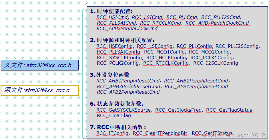
1.3 RCC相关头文件和固件库源文件
