linux pl320 mbox控制器驱动分析 - (2)消息传递示例
- 1 Messaging from Core0 to Core1
- 2 Back-to-back messaging from Core0 to Core1
- 3 Messaging from Core0 to Cores 1, 2, and 3 using Auto Acknowledge
- 4 Auto Link messaging from Core0 to Core1 using Mailbox0 and Mailbox1
pl320手册的下载地址为:
https://developer.arm.com/documentation/ddi0306/b/?lang=en
https://developer.arm.com/Processors/PL320
1 Messaging from Core0 to Core1
In this example system, there are two cores and four mailboxes. Core0 is the source core and Core1 is the destination core. Core0 uses Channel ID1 and Core1 uses Channel ID2. Core0 sends a message to Core1 using Mailbox0. This example assumes that the IPCM is not in integration test mode. Mailboxes 1-3 are inactive and Auto Acknowledge and Auto Link are disabled. Figure 2.5 shows the configuration.
在这个示例系统中,有两个核心和四个邮箱。 Core0 是源core,Core1 是目标core。 Core0 使用 Channel ID1,Core1 使用 Channel ID2。 Core0 使用 Mailbox0 向 Core1 发送消息。此示例假定 IPCM 未处于集成测试模式。邮箱 1-3 处于非活动状态,自动确认和自动链接被禁用。图 2.5 显示了配置。
Figure 2.5. Configuration, messaging from Core0 to Core1
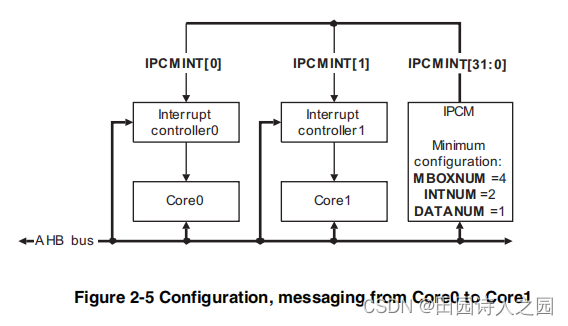
Figure 2.5. Configuration, messaging from Core0 to Core1
Figure 2.6 shows the messaging sequence.
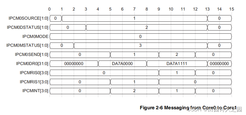
Figure 2.6. Messaging from Core0 to Core1
In this example, the following sequence occurs:
- 1 Core0 gains control of Mailbox 0 and identifies itself as the source core by setting bit 0 in the IPCM0SOURCE Register.
- 2 Core0 enables interrupts to Core?0 and Core1 by setting bits 0 and 1 in the IPCM0MSTATUS Register.
- 3 Core0 defines the destination core by setting bit 1 in the IPCM0DSTATUS Register.
- 4 Core0 programs the data payload, DA7A0000.
- 5 Core0 sets Mailbox Send Register bit 0 to trigger the Mailbox0 interrupt to Core 1.
- 6 Core1 reads the IPCMRIS1 Register to determine which mailbox caused the interrupt. In this case, only Mailbox0 is indicated.
- 7 Core1 reads the data payload.
- 8 Core1 optionally updates the data payload with the Acknowledge data, DA7A1111.
- 9 Core1 clears bit 0 and sets bit 1 in the IPCM0SEND Register to clear its interrupt and provide the Manual Acknowledge interrupt back to Core0.
- 10 Core0 reads the IPCMRIS0 Register to determine which mailbox caused the interrupt. Again, only Mailbox0 is indicated.
- 11 Core0 reads the Acknowledge payload data.
- 12 Core0 clears bit 1 in the Mailbox Send Register to clear its interrupt.
- 13 Core0 releases ownership of the mailbox by clearing the IPCM0SOURCE Register, which in turn clears the IPCM0DSTATUS, IPCM0MSTATUS, and IPCM0DR0 Registers.
note:
Core0 can hold on to the mailbox to send another data message by not clearing the IPCM0SOURCE Register at step 13.
通过在第 13 步不清除 IPCM0SOURCE 寄存器,Core0 可以保留邮箱发送另一条数据消息。
2 Back-to-back messaging from Core0 to Core1
Back-to-back messaging from Core0 to Core1
In this example system, there are two cores and four mailboxes. Core0 is the source core and Core1 is the destination core. Core0 uses Channel ID1 and Core1 uses Channel ID2, as in Back-to-back messaging from Core0 to Core1. Core0 sends a message to Core1, obtains an acknowledge, and sends another message to Core1, which is also acknowledged. This example assumes that the IPCM is not in integration test mode. Mailboxes 1-3 are inactive and Auto Acknowledge and Auto Link are disabled. Figure 2.7 shows the configuration.
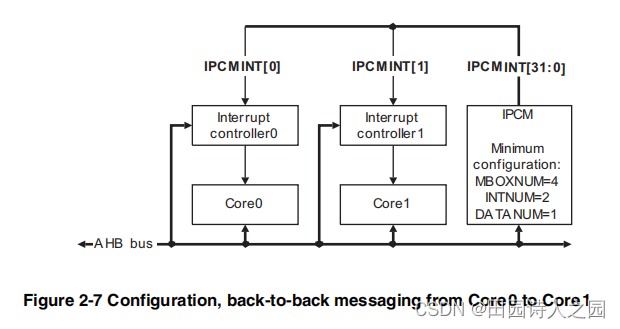
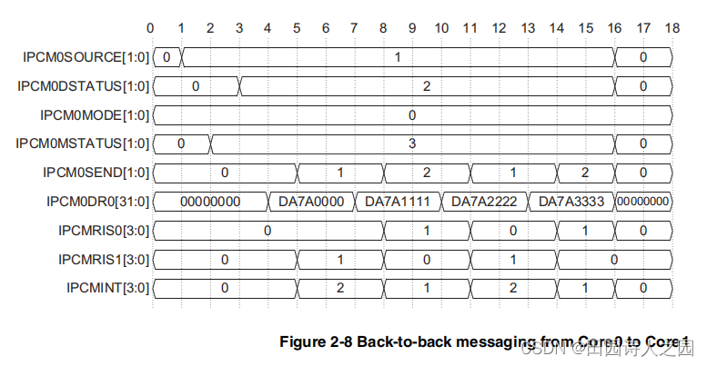
In this example, the following sequence occurs:
- Core0 gains control of Mailbox0 and identifies itself as the source core by setting bit 0 in the IPCM0SOURCE Register.
- Core0 enables interrupts to Core0 and Core1 by setting bits 0 and 1 in the IPCM0MSTATUS Register.
- Core0 defines the destination core by setting bit 1 in the IPCM0DSTATUS Register.
- Core0 programs the data payload, DA7A0000.
- Core0 sets bit 0 of the IPCM0SEND Register to send the interrupt to the destination core.
- Core1 reads the IPCMRIS1 Register and reads the data payload.
- Core1 optionally updates the data payload for the Acknowledge, DA7A1111.
- Core1 clears bit 0 and sets bit 1 in the IPCM0SEND Register to provide the Manual Acknowledge back to Core?0.
- Core0 reads the IPCMRIS0 Register and reads the data payload.
- Core0 programs the data payload for the next message, DA7A2222.
- Core0 clears bit 1 and sets bit 0 of the IPCM0SEND Register to send the interrupt to the destination core.
- Core1 reads the IPCMRIS1 Register and reads the data payload.
- Core1 optionally updates the data payload for the Acknowledge, DA7A3333.
- Core1 clears bit 0 and sets bit 1 in the IPCM0SEND Register to provide the Manual Acknowledge back to Core0.
- Core0 reads the IPCMRIS0 Register and reads the data payload.
- Core0 clears the interrupt and releases ownership of the mailbox by clearing the IPCM0SOURCE Register, which in turn clears the IPCM0DSTATUS, IPCM0MSTATUS, IPCM0SEND, and IPCM0DR0 Registers.
3 Messaging from Core0 to Cores 1, 2, and 3 using Auto Acknowledge
In this example system, there are four cores and four mailboxes:
- Core0 uses Channel ID1
- Core1 uses Channel ID2
- Core2 uses Channel ID4
- Core3 uses Channel ID8.
Core0 is the source core and sends a message to three destination cores, 1, 2, and 3. This example assumes that the IPCM is not in integration test mode. Mailboxes 1-3 are inactive and Auto Link is disabled. Figure 2.9 shows the configuration.
Core0 是源core,向三个目标内核 1、2 和 3 发送消息。此示例假定 IPCM 未处于集成测试模式。邮箱 1-3 处于非活动状态并且自动链接被禁用。图 2.9 显示了配置。
Figure 2.9. Configuration, messaging from Core0 to Cores 1, 2, and 3 using Auto Acknowledge
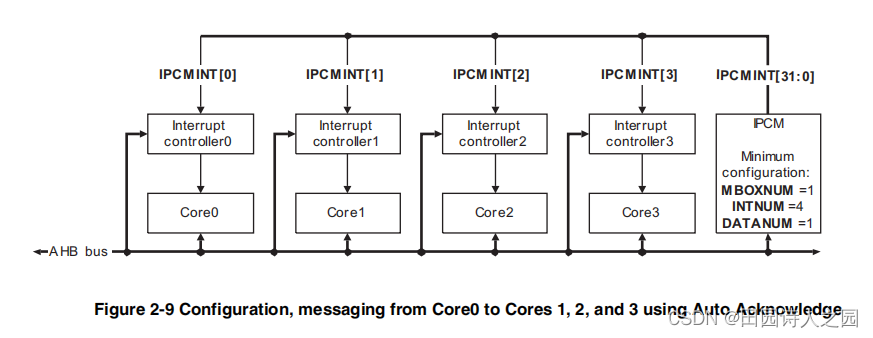
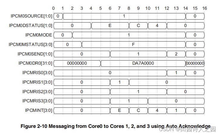
In this example, the following sequence occurs:
- Core0 gains control of Mailbox0 and identifies itself as the source core by setting bit 0 in the IPCM0SOURCE Register.
- Core0 sets Mailbox Mode Register bit 0 to put the mailbox into Auto Acknowledge mode.
- Core?0 enables interrupts to Core0, Core1, Core2, and Core3 by setting bits 0, 1, 2, and 3 in the IPCM0MSTATUS Register.
- Core0 defines the destination cores by setting bits 1, 2, and 3 in the IPCM0DSTATUS Register.
- Core0 programs the data payload, DA7A0000.
- Core0 sets bit 0 of the IPCM0SEND Register to send the interrupts to the destination cores.
- Core1 reads the IPCMRIS1 Register and reads the data payload.
- Core1 clears bit 1 in the IPCM0DSTATUS Register.
- Core3 reads the IPCMRIS3 Register and reads the data payload.
- Core3 clears bit 3 in the IPCM0DSTATUS Register.
- Core2 reads the IPCMRIS2 Register and reads the data payload.
- Core2 clears bit 2 in the IPCM0DSTATUS Register. As the final Mailbox Destination Register bit is cleared, the mailbox automatically detects this, clears Mailbox Send Register bit 0 and sets Mailbox Send Register bit 1 to provide the Auto Acknowledge back to the source core, Core?0. The data registers are not updated in Auto Acknowledge mode.
- Core0 reads Status0 and reads the data payload.
- Core 0 clears the interrupt and releases ownership of the mailbox by clearing the IPCM0SOURCE register, which in turn clears the IPCM0SEND and IPCM0DR0 Registers.
Note
If Core0 has another message to send, it can maintain ownership of the mailbox by keeping the IPCM0SOURCE Register set, and updating the IPCM0DSTATUS, IPCM0MODE, IPCM0MSTATUS, and IPCM0DR0 Registers with the new message at step 14.
如果 Core0 要发送另一条消息,它可以通过保持 IPCM0SOURCE 寄存器设置并在第 14 步用新消息更新 IPCM0DSTATUS、IPCM0MODE、IPCM0MSTATUS 和 IPCM0DR0 寄存器来维护邮箱的所有权。
4 Auto Link messaging from Core0 to Core1 using Mailbox0 and Mailbox1
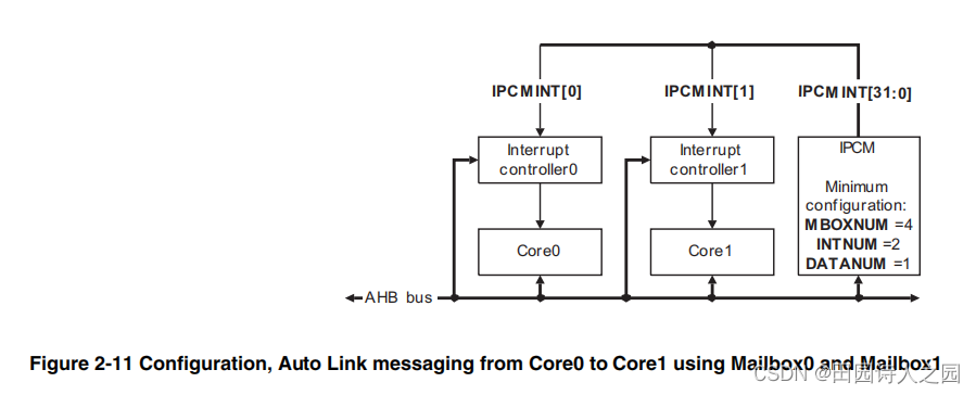
In this example system, there are two cores and four mailboxes. Core0 is the source core and Core1 is the destination core. Core?0 uses Channel ID1 and Core1 uses Channel ID2. Core0 sets up Mailbox0 and Mailbox1 in Auto Link mode, and sends a message to Core1. Core1 responds to each interrupt separately and acknowledges both. Core0 only obtains an acknowledge interrupt when Core1 has finished with the final message. This example assumes that the IPCM has interrupts enabled and is not in integration test mode. Mailboxes 2-3 are inactive and Auto Acknowledge is disabled. Figure 2.11 shows the configuration.
在这个示例系统中,有两个核心和四个邮箱。 Core0 是源内核,Core1 是目标内核。 Core?0 使用 Channel ID1,Core1 使用 Channel ID2。 Core0 将 Mailbox0 和 Mailbox1 设置为 Auto Link 模式,并向 Core1 发送消息。 Core1 分别响应每个中断并确认两者。 Core0 仅在 Core1 完成最终消息时获得确认中断。此示例假定 IPCM 已启用中断且未处于集成测试模式。邮箱 2-3 处于非活动状态并且自动确认被禁用。图 2.11 显示了配置。
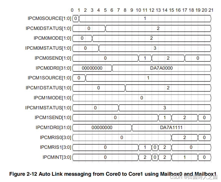
Figure 2.11. Configuration, Auto Link messaging from Core0 to Core1 using Mailbox0 and Mailbox1
In this example, the following sequence occurs:
- Core0 gains control of Mailbox0 and sets bit 0 in the IPCM0SOURCE Register.
- Core0 gains control of Mailbox1 and sets bit 0 in the IPCM1SOURCE Register.
- Core0 links Mailbox?0 to Mailbox1 by setting bit 1 in the IPCM0MODE Register.
- Core0 enables interrupts to Core0 and Core1 by setting bits 0 and 1 in the IPCM0MSTATUS Register.
- Core0 defines the destination core of Mailbox?0 by setting bit 1 in the IPCM0DSTATUS Register.
- Core0 programs the data payload of Mailbox?0 by setting the IPCM0DR0 Register to DA7A0000.
- Core0 enables interrupts to Core0 and Core1 by setting bits 0 and 1 in the IPCM1MSTATUS Register.
- Core0 defines the destination core of Mailbox1 by setting bit 1 in the IPCM1DSTATUS Register.
- Core0 programs the data payload of Mailbox1 by setting Data1 to DA7A1111.
- Core0 sets bit 1 in the IPCM0SEND Register to send the message in Mailbox0.
- Core1 reads the IPCMRIS1 Register and reads the data payload in Mailbox0.
- Core1 clears bit 0 and sets bit 1 in the IPCM0SEND Register to provide the Manual Acknowledge back to Core0.
Note
There is no acknowledge interrupt to Core 0. - The message in Mailbox1 is automatically sent, triggered by bit 1 in the IPCM0SEND Register going HIGH and Auto Link mode being active.
- Core 1 reads the IPCMRIS1 Register and reads the data payload in Mailbox1.
- Core1 clears bit 0 and sets bit 1 in the IPCM1SEND Register to provide the Manual Acknowledge back to Core0.
Note
This sends the acknowledge interrupt to Core0.
- Core0 reads the IPCMRIS0 Register indicating that Mailbox1 has an acknowledge message. This indicates that the linked messages have all been sent. Core0 also reads the optional acknowledge data payload in Mailbox0.
- Core0 clears bit 1 in the IPCM0SEND Register.
- Core0 reads the optional acknowledge data payload in Core1.
- Core0 clears bit 1 in the IPCM1SEND Register.

