几何算法——7.Blending(倒角)的调研、设计及算法
- 1 Parasolid的Blending
- 1.1 关于Parasolid的BlendSurface
- 1.2 Edge Blending
- 1.2.1 Rolling-ball blends
- 1.2.2 Variable rolling-ball blends
- 1.2.3 Chamfers
- 1.2.3.1 face offset chamfers
- 1.2.3.2 apex-range chamfer blends
- 1.2.3.3 第三种 chamfer blends
- 1.3 Face-Face Blending
- 1.4 Three-Face Blending
- 2 Acis的Blending
- 3 其他
- 4 Blending的算法设计
1 Parasolid的Blending
Parasolid提供了三种形式的blending:
- Edge Blending
- Face-Face Blending
- Three-Face Blending
Edge Blending和Face-Face Blending不应该被认为是替代方案,而是两种强有力地互补的方法,因为它们的优点和缺点是互补的。Three-Face Blending是Face-Face Blending的一种特殊情况,因为其混合是在三组面(而不是两组)之间创建的。
1.1 关于Parasolid的BlendSurface
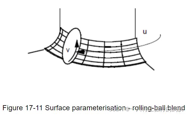
Rolling-ball blend
A rolling-ball blend has a parametric representation of the form:
R
(
u
,
v
)
=
C
(
u
)
+
r
∗
X
(
u
)
c
o
s
(
v
∗
a
(
u
)
)
+
r
Y
(
u
)
s
i
n
(
v
∗
a
(
u
)
)
R(u,v) = C(u) + r*X(u)cos(v*a(u)) + r Y(u)sin(v*a(u))
R(u,v)=C(u)+r∗X(u)cos(v∗a(u))+rY(u)sin(v∗a(u))
where:
- C(u) is the spine curve, which is the locus of the centre of the rolling ball,
- r is the blend radius,
- X(u) and Y(u) are unit vectors such that d C ( u ) / d u , dC(u)/du, dC(u)/du, X(u) and Y(u) form an orthogonal set and X(u) is in the direction R(u,0) - C(u),
- a(u) is the angle subtended by points on the boundary curves at the spine,
- X, Y and a are expressed as functions of u, as their values change with u.
- R(u,0) and R(u,1) are the curves where the blendsf meets the supporting geometries.
1.2 Edge Blending
Edge Blending有三种类型:
- Rolling-ball blends
- Variable rolling-ball blends
- Chamfers
如下图:

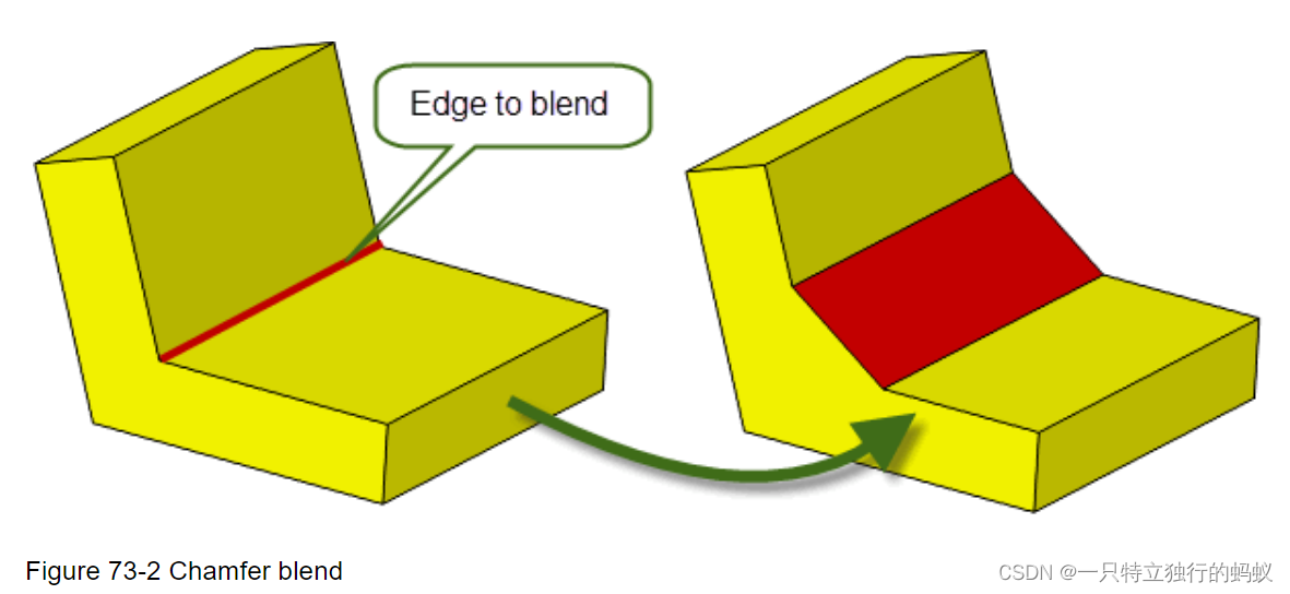
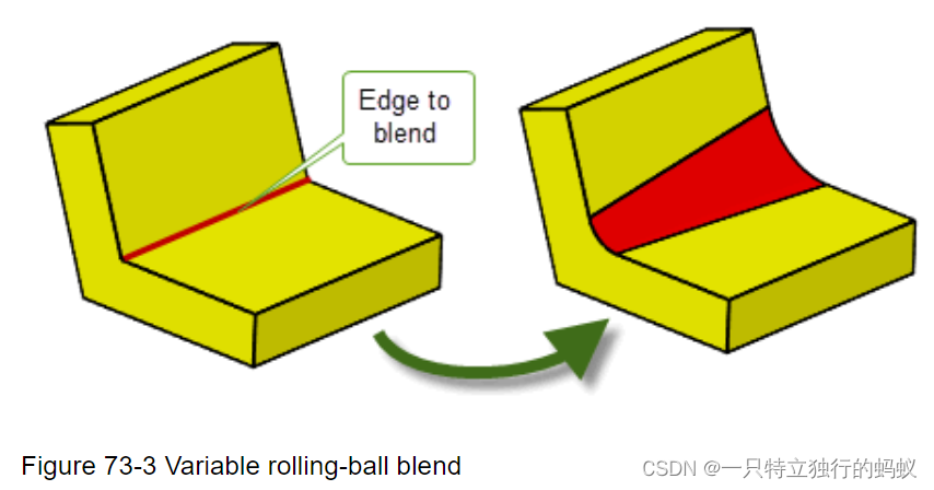
You can create each type of edge blend on general bodies, so long as the body is locally manifold in the area of the blend.
Rolling-ball blends
Variable rolling-ball blends
可变滚动球共混物是指那些共混物的尺寸(例如,在具有圆形截面的共混物的情况下,共混半径)沿被混合的边链变化的共混物,如图73-3所示。可变滚动球共混物可以有圆形、圆锥或曲率连续的截面。
Chamfers
有两种类型的倒角混合物:面偏移倒角和顶点范围倒角。
面偏移倒角混合可以通过使用PK_EDGE_set_blend_chamfer中的range_1和range_2参数或PK_EDGE_set_blend_chain中的选项定义的偏移面之间的交集来确定。
顶点范围倒角提供了另一种控制倒角混合边界的方法,可以使用PK_EDGE_set_blend_chain中的选项来创建。
1.2.1 Rolling-ball blends
In particular it is often difficult to avoid falling over the illegal overlap/intersection type errors caused by choosing too large blend radii. However, the following rules and tips are worth considering but always remember that it is best to make and fix blends in small groups:
原文档中讲到,有以下一些rules and tips对于blend值得考虑:
Blending one edge at a vertex
If more than three edges meet at a vertex it is usually possible to blend one of them providing
that:
The ranges must be sufficiently small and the configuration such that the sides of the blend
end on other edges at the same vertex.
It is possible to cap the end of the blend with existing faces, extending at most two of the
adjoining faces.
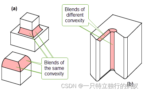
Blending two edges at a three-edge vertex
You can successfully blend two of the edges at a three-edge vertex in the following situations:
If any two of the three edges A, B, and C, are of the same convexity, they can be blended
(see Figure 73–8 (a)).
If edges A and B are of one convexity, and edge C is of opposite convexity, you can blend
A and C or B and C only if the blend on edge C is of constant radius (see Figure 73–8 (b)).
Blending three edges at a three-edge vertex
When all three edges of a three-edge vertex are blended simultaneously (put them on and fix
them as a group), an extra blend face is added to smooth out the vertex.
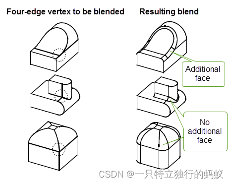
Blending two edges at a four-edge vertex
When blending two edges of a four-edge vertex with a rolling-ball blend, the following constraints
are applied:
the other pair, i.e. non-blended edges, are tangent or do not share a face and are of the
same convexity
the convexity of the blend does not change at the vertex of the two blended edges
1.2.2 Variable rolling-ball blends
The positions array (and its corresponding n_positions option), lets you specify a list of vectors along the blend chain at which to apply blend parameters specified in the call to PK_EDGE_set_blend_chain.
For a simple blend, you just need to apply controls at the start and end of the blend, you should therefore specify at least two vectors in positions : the start and end of the blend chain (regardless of the number of edges in the chain). Thus, n_positions must be at least 2.
For more complex blends, you might need to apply controls at other points along the blend chain, in which case you can just add additional vectors to the positions array that represent the positions at which you need to place those controls.
An important use of the positions array is to indicate points in the chain where the parameters change instantaneously.
Specifying blend ranges
You use the primary_sizes and secondary_sizes options to specify a range of offset values for a variable radius blend. These are both arrays whose values correspond to entries in the positions array.
Figure 74-4 shows how the blend is defined for a given value, X, in the positions array. The corresponding offsets from the primary_sizes and secondary_sizes arrays are used to create a point on the blend spine, as well as contact points for the blend boundary.
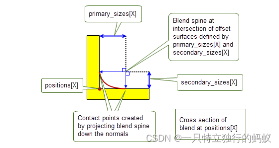
从这张图中的解释,我们可以看出,它说Blend spine at intersection of offset surfaces说明这个spine是两个offset surface的交线。同时,他说constact points create by projecting。这也符合rolling ball的定义和offset的定义。
从这个地方,可以推断出,这个spine可能确实是两个offset surface求交得到的。(这和我当时做倒角的时候一样)。至于offset surface就比较好说了,是从原来的face的surface做一个offset得到的。但是这个地方要注意的是,对于变半径的倒角,能或者应该如何定义它关联的offset surface?但我觉得,对于变半径的的blending surface的计算,应该不是用的这种计算方法,而可能是沿着blending edge,在上面取点然后用project计算在两face上的contact point,从而生成曲面的?
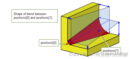
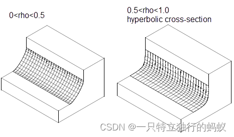
The shape of the blend cross-section depends on the nature of the supplied primary_sizes and secondary_sizes :(具体详情在parasolid文档“74.2.2.4 Controlling cross section shape中”有详细分类介绍)
If corresponding values in primary_sizes and secondary_sizes for each entry in positions along the blend chain are equal, and the rho values array is PK_ENTITY_null or all rho values are zero , the blend has a circular cross-section.
If only primary_sizes are specified, and the rho values array is PK_ENTITY_null or all rho values are zero, then Parasolid uses the same values for the corresponding secondary_sizes for each entry in positions , and the blend has a circular cross-section.
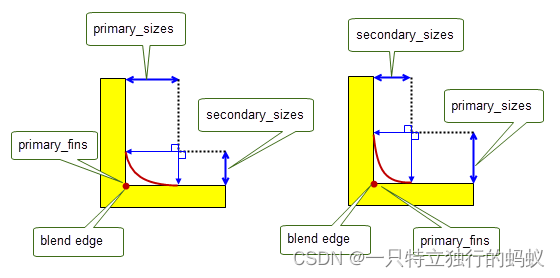
If corresponding values in primary_sizes and secondary_sizes for each entry in positions along the blend chain are different, and the rho values array is PK_ENTITY_null or all rho values are zero, the blend has a an elliptical cross-section. // 椭圆截面的blend
If you define an elliptical blend, you need to use the primary_fins option to specify which way round the resulting asymmetrical cross-section should be applied.
1.2.3 Chamfers
1.2.3.1 face offset chamfers
Face offset chamfer blends can be determined by the intersection between offset surfaces that are defined using the range_1 and range_2 arguments in PK_EDGE_set_blend_chamfer. The effect of these arguments on the position and size of the chamfer is shown in Figure 74-11.
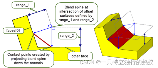
The resulting chamfer depends on both the angle between the faces on either side of the specified edges, and the relative sizes of range_1 and range_2 . Figure 74-12 shows some examples。
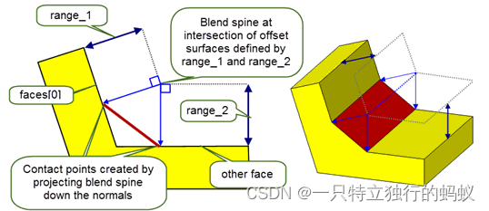
从上图也可以看出,这个定义的chamfer也是用和倒圆角一样的方法,先用两个曲面的offset surface求交得到中心脊线,然后再分别投影到两个surface上得到对应的contact points。
1.2.3.2 apex-range chamfer blends
This section describes options that are specifically available to PK_EDGE_set_blend_chain for controlling apex-range chamfers.
The apex is a point where the tangents from two underlying faces at the contact points cross as shown in Figure 74-13. The apex range is the distance between the contact points and the apex.
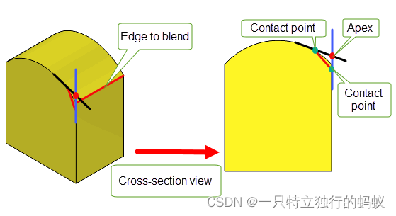
1.2.3.3 第三种 chamfer blends
PK_blend_size_angle_c控制的。与前两种chamfer对比如下表:
The primary_size_type and secondary_size_type options indicate how the values of primary_sizes and secondary_sizes should be interpreted as follows:
| Value | Description |
|---|---|
| PK_blend_size_face_offset_c | The size represents the distance of the face offset. If both primary_size_type and secondary_size_type options are set to this value, a face offset chamfer blend is produced.This is the default |
| PK_blend_size_apex_range_c | The size represents the range to the apex of the blend. |
| PK_blend_size_angle_c | The size represents the angle made by the chord between the contact points and the tangent plane of the contact point on the other side of the blend. |
Figure 74-14 shows the results of creating an apex-range chamfer when the primary_size_type and secondary_size_type options are set to the same values.
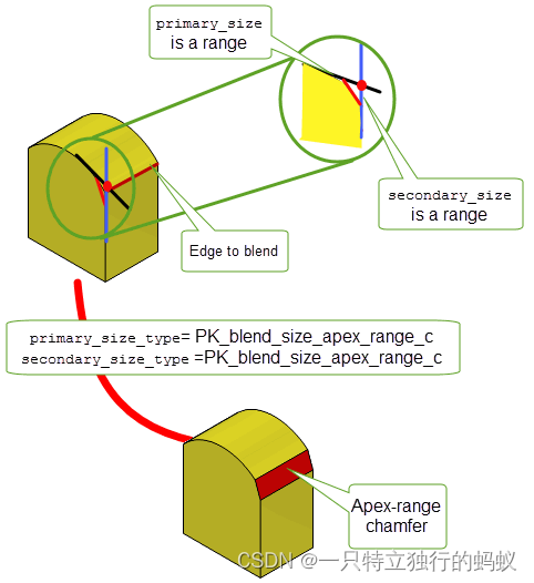
Figure 74-15 shows the result when primary_size_type is set to PK_blend_size_angle_c and secondary_size_type is set to PK_blend_size_apex_range_c.
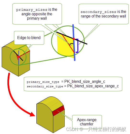
(未完待续)
1.3 Face-Face Blending
In addition to edge blending, Parasolid provides functionality to create blends between two sets of (not necessarily connected) faces. This operation is known as face-face blending.
Figure 76-1 shows an example where two disjoint sheet bodies have been joined together by creating a face-face blend between them.
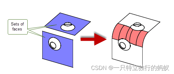
Face-face blending differs from edge blending as follows:
- The sets of faces to be blended do not need to be adjacent, or even in the same body.
- Face-face blends are created and fixed in a single operation. There is no such thing as an unfixed face-face blend.
(未完待续,持续更新中)


