本文介绍 openvins 中IMU仿真时基于控制轨迹和SPline插值,并计算IMU输出,的原理和代码。
参考
Open-vins中关于仿真的描述:https://docs.openvins.com/simulation.html
Open-vins论文:https://pgeneva.com/downloads/papers/Geneva2020ICRA.pdf
Open-vins所采用的SE3插值论文:https://link.springer.com/article/10.1007/s11263-015-0811-3
上述论文提到的BSpline的矩阵表示:https://xiaoxingchen.github.io/2020/03/02/bspline_in_so3/general_matrix_representation_for_bsplines.pdf
open-vins中的仿真部分结构
open-vins的文件目录中,如下文件与仿真有关:
ov_core/
	src/
		sim/
			BsplineSE3.cpp
			BsplineSE3.h
ov_msckf/
	src/
		sim/
			Simulator.cpp
			Simulator.h
		test_sim_meas.cpp
ov_data/
	sim/
		xxx.txt
其中,test_sim_meas.cpp 是仿真程序入口,调用的主函数为 Simualtor 类,openvins中所有的内容需要基于 ov_core 这个核心,具体的插值部分用的是 BsplineSE3 这个类。而载入的轨迹数据格式,可以参考 ov_data 路径的文件。
test_sim_meas.cpp
里面核心的函数是 get_next_imu(time_imu, wm, am),其根据类内轨迹数据,计算再某一时刻的imu输出。
get_next_imu
位于 Simulator 类内,主要内容有两个:利用 Bspline 插值得到加速度和角速度, spline->get_acceleration;再添加随机游走和测量噪声。
get_acceleration
位于 BsplineSE3 类,主要内容包括:
- 获取轨迹的控制点:
find_bounding_control_points() - 计算 De Boor-Cox 矩阵系数
- 轨迹插值,获得当前时刻的pose
- 将pose转为加速度和角速度(世界系)
- 将世界系的加速度和角速度,转到 IMU 系
针对1,只是把轨迹中当前时刻点的前后各2个pose拿出来,即pose0,1,2,3。当前需要插值的时刻是位于1和2之间。
原理解释
De Boor-Cox矩阵系数与轨迹插值
首先,openvins论文中给出的插值公式如下:
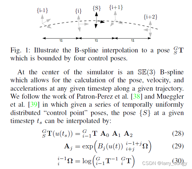 这个公式非常简略,看不出来在干什么。简单来说,就是为了计算 u(ts) 时刻得位姿 T,这个位姿是从S系转到G(世界)系的,那么此时需要用 (i-1)时刻的和
A
0
,
A
1
,
A
2
A_0, A_1,A_2
A0,A1,A2 这4个矩阵计算。式(29)和(30)给出了
A
A
A的表达式。
想要了解为什么这么算,就需要阅读参考文献[38]:
A Spline-Based Trajectory Representation for Sensor Fusion and Rolling Shutter Cameras
基于SE3的Bspline插值
这篇文章提出的动机是,多传感器融合时,不可能多个传感器完全在同一时刻获取数据,因此需要Bspline插值,因此提出了在SE3插值。
具体地,对于插值方法,有两种表示,分别是(1)和(2),里面的
B
B
B和
B
˜
\~{B}
B˜是两种不同表示的基,但本质上一样。这里采用的是第二种表示。
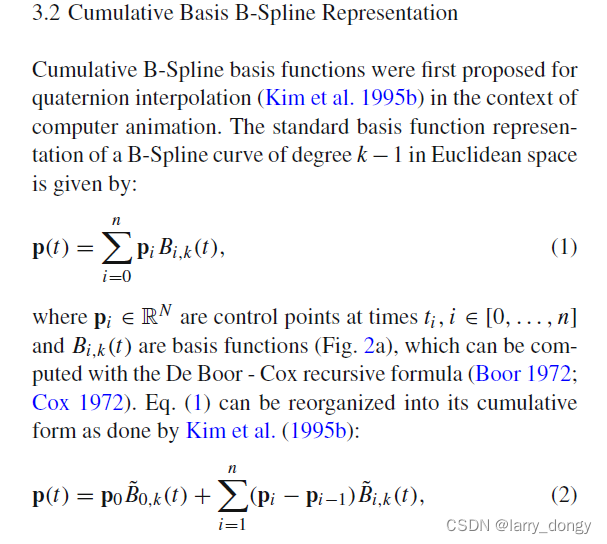
这种表示对于 SE3 的公式为:
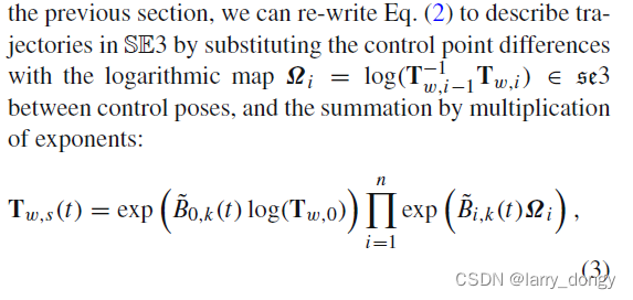 这里的符号表示和openvins的不同,这里s表示插值时刻,w表示世界系。
Ω
i
\Omega_i
Ωi 就是上面的
l
o
g
(
T
w
,
i
−
1
−
1
,
T
w
,
i
)
log(T_{w,i-1}^{-1}, T_{w,i})
log(Tw,i−1−1,Tw,i),和上一位姿间的
s
e
3
se3
se3。
此时上述(3)式的变量只剩
B
˜
0
,
k
(
t
)
\~B_{0,k}(t)
B˜0,k(t),这个的计算方式由 Qin2000(General Matrix Representations for B-Splines) 这篇论文给出。这篇论文太复杂了看不懂,简单概括就是将BSpline用矩阵进行了表示。这里略过。
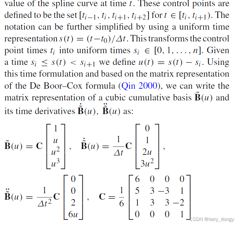
由于目标是为IMU提供数据,因此希望加速度是连续的,因此轨迹曲线采用C2连续(即二阶导连续),C2连续只需要4个控制点,即前面2个后面2个,此时的矩阵是 4x4 的。上式的
u
u
u即插值相对于上一控制点的增量。同时,这里给出了
B
˜
\~B
B˜的一阶导和二阶导。
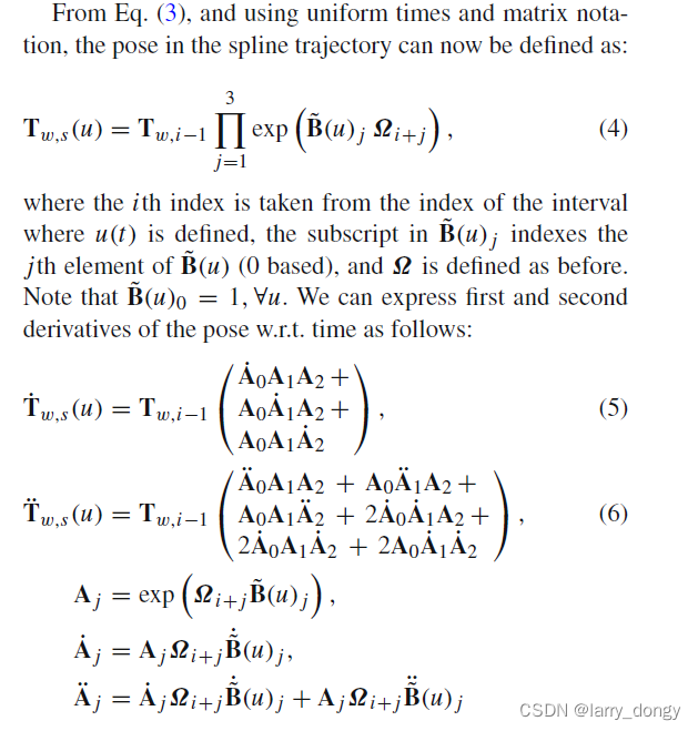
接下来,论文给出了轨迹插值结果,以及插值的一阶导(速度)和二阶导(加速度)表达式。接下来的
A
A
A就和openvins的一致了。
由pose计算IMU系得加速度与角速度
上面计算完,只是得到了轨迹相对于轨迹所在坐标系(即世界系)的轨迹、速度和加速度,接下来要求相对于IMU系。这个模型就比较简单:

加速度,加上重力后,转到IMU系;
角速度,需要经过旋转矩阵求导,再转到IMU系。
代码与原理的对应
直接复制出来 openvins 中 BsplineSE3 中获取加速度和角速度的代码:
//~ 输入:待插值的时间戳;
/*~ 输出:IMU的加速度、角速度,以及一些姿态量;

~*/
bool BsplineSE3::get_acceleration(double timestamp, Eigen::Matrix3d &R_GtoI, Eigen::Vector3d &p_IinG,
	Eigen::Vector3d &w_IinI, Eigen::Vector3d &v_IinG, Eigen::Vector3d &alpha_IinI, Eigen::Vector3d &a_IinG) {

  // Get the bounding poses for the desired timestamp
  double t0, t1, t2, t3;
  Eigen::Matrix4d pose0, pose1, pose2, pose3;
  bool success = find_bounding_control_points(timestamp, control_points, t0, pose0, t1, pose1, t2, pose2, t3, pose3);

  // Return failure if we can't get bounding poses
  if (!success) {
    alpha_IinI.setZero();
    a_IinG.setZero();
    return false;
  }
  //~ 这里就是计算上述B矩阵,B的一阶导,二阶导矩阵;
  // Our De Boor-Cox matrix scalars
  double DT = (t2 - t1);
  double u = (timestamp - t1) / DT;
  double b0 = 1.0 / 6.0 * (5 + 3 * u - 3 * u * u + u * u * u);
  double b1 = 1.0 / 6.0 * (1 + 3 * u + 3 * u * u - 2 * u * u * u);
  double b2 = 1.0 / 6.0 * (u * u * u);
  double b0dot = 1.0 / (6.0 * DT) * (3 - 6 * u + 3 * u * u);
  double b1dot = 1.0 / (6.0 * DT) * (3 + 6 * u - 6 * u * u);
  double b2dot = 1.0 / (6.0 * DT) * (3 * u * u);
  double b0dotdot = 1.0 / (6.0 * DT * DT) * (-6 + 6 * u);
  double b1dotdot = 1.0 / (6.0 * DT * DT) * (6 - 12 * u);
  double b2dotdot = 1.0 / (6.0 * DT * DT) * (6 * u);

  // Cache some values we use alot
  Eigen::Matrix<double, 6, 1> omega_10 = log_se3(Inv_se3(pose0) * pose1);
  Eigen::Matrix<double, 6, 1> omega_21 = log_se3(Inv_se3(pose1) * pose2);
  Eigen::Matrix<double, 6, 1> omega_32 = log_se3(Inv_se3(pose2) * pose3);
  Eigen::Matrix4d omega_10_hat = hat_se3(omega_10);
  Eigen::Matrix4d omega_21_hat = hat_se3(omega_21);
  Eigen::Matrix4d omega_32_hat = hat_se3(omega_32);

	// 这里计算了A0~A2,以及一阶导、二阶导
  // Calculate interpolated poses
  Eigen::Matrix4d A0 = exp_se3(b0 * omega_10);
  Eigen::Matrix4d A1 = exp_se3(b1 * omega_21);
  Eigen::Matrix4d A2 = exp_se3(b2 * omega_32);
  Eigen::Matrix4d A0dot = b0dot * omega_10_hat * A0;
  Eigen::Matrix4d A1dot = b1dot * omega_21_hat * A1;
  Eigen::Matrix4d A2dot = b2dot * omega_32_hat * A2;
  Eigen::Matrix4d A0dotdot = b0dot * omega_10_hat * A0dot + b0dotdot * omega_10_hat * A0;
  Eigen::Matrix4d A1dotdot = b1dot * omega_21_hat * A1dot + b1dotdot * omega_21_hat * A1;
  Eigen::Matrix4d A2dotdot = b2dot * omega_32_hat * A2dot + b2dotdot * omega_32_hat * A2;

  // Get the interpolated pose
  Eigen::Matrix4d pose_interp = pose0 * A0 * A1 * A2;
  R_GtoI = pose_interp.block(0, 0, 3, 3).transpose();
  p_IinG = pose_interp.block(0, 3, 3, 1);

  // Get the interpolated velocities
  // NOTE: Rdot = R*skew(omega) => R^T*Rdot = skew(omega)
  //~ 式(5),计算角速度插值,角速度转回IMU系
  Eigen::Matrix4d vel_interp = pose0 * (A0dot * A1 * A2 + A0 * A1dot * A2 + A0 * A1 * A2dot);
  w_IinI = vee(pose_interp.block(0, 0, 3, 3).transpose() * vel_interp.block(0, 0, 3, 3));
  v_IinG = vel_interp.block(0, 3, 3, 1);

  // Finally get the interpolated velocities
  // NOTE: Rdot = R*skew(omega)
  // NOTE: Rdotdot = Rdot*skew(omega) + R*skew(alpha) => R^T*(Rdotdot-Rdot*skew(omega))=skew(alpha)
  //~ 式(6),计算速度插值,加速度转回IMU系
  Eigen::Matrix4d acc_interp = pose0 * (A0dotdot * A1 * A2 + A0 * A1dotdot * A2 + A0 * A1 * A2dotdot + 2 * A0dot * A1dot * A2 + 2 * A0 * A1dot * A2dot + 2 * A0dot * A1 * A2dot);
  Eigen::Matrix3d omegaskew = pose_interp.block(0, 0, 3, 3).transpose() * vel_interp.block(0, 0, 3, 3);
  alpha_IinI = vee(pose_interp.block(0, 0, 3, 3).transpose() * (acc_interp.block(0, 0, 3, 3) - vel_interp.block(0, 0, 3, 3) * omegaskew));
  a_IinG = acc_interp.block(0, 3, 3, 1);
  return true;
}

