1. 功能说明
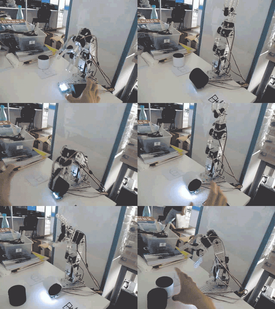
本实验要实现的功能是:将黑、白两种颜色的工件分别放置在传感器上时,机械臂会根据检测到的颜色,将工件搬运至写有相应颜色字样区域。
2. 使用样机
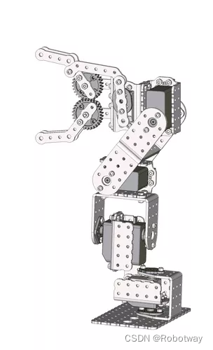
本实验使用的样机为4自由度串联机械臂。
3. 运动功能实现
3.1 电子硬件
在这个示例中,我们采用了以下硬件,请大家参考:
| 主控板 | Basra(兼容Arduino Uno) |
| 扩展板 | Bigfish2.1 |
| 传感器 | TCS3200颜色识别 |
| 电池 | 7.4V锂电池 |
在4自由度串联机械臂底座上安装一个 TCS3200颜色识别传感器 ,用于检测工件的RGB值。
3.2 编写程序
编程环境:Arduino 1.8.19
可以事先利用TCS3200颜色识别传感器检测一下两个工件的的颜色数据,根据颜色数据的特征来确定判断语句的写法,尽量利用R、G、B数值中差别最大的那个作为区分颜色的主要依据。TCS3200颜色识别传感器的检测方法可以参考 TCS3200颜色识别传感器 。
编写并烧录以下程序(Color_test.ino),该程序将实现演示视频中的动作。
/*------------------------------------------------------------------------------------

  版权说明:Copyright 2023 Robottime(Beijing) Technology Co., Ltd. All Rights Reserved.

           Distributed under MIT license.See file LICENSE for detail or copy at

           https://opensource.org/licenses/MIT

           by 机器谱 2023-02-03 https://www.robotway.com/

  ------------------------------

  实验接线:舵机接口依次D4、D7、D11、D3、D8; 颜色传感器接在A0、A2、A3口上

------------------------------------------------------------------------------------*/

/*I will sorting black and white things according to the color_test Code.

Put the black things in the left.Put the white thing int the right*/

#include <MsTimer2.h>

//把TCS3200颜色传感器各控制引脚连到Arduino数字端口

#define S0     A0   //物体表面的反射光越强,TCS3002D的内置振荡器产生的方波频率越高,

#define S1     A1   //S0和S1的组合决定输出信号频率比率因子,,比例因子为2%

                   //比率因子为TCS3200传感器OUT引脚输出信号频率与其内置振荡器频率之比

#define S2     A2   //S2和S3的组合决定让红、绿、蓝,哪种光线通过滤波器

#define S3     0

#define OUT    2   //TCS3200颜色传感器输出信号输入到Arduino中断0引脚,并引发脉冲信号中断

                  //在中断函数中记录TCS3200输出信号的脉冲个数

#define LED    A3   //控制TCS3200颜色传感器是否点亮

int   g_count = 0;    // 计算与反射光强相对应TCS3200颜色传感器输出信号的脉冲数

// 数组存储在1s内TCS3200输出信号的脉冲数,它乘以RGB比例因子就是RGB标准值

int   g_array[3];

int   g_flag = 0;     //滤波器模式选择顺序标志

float g_SF[3];       // 存储从TCS3200输出信号的脉冲数转换为RGB标准值的RGB比例因子

int color=0;


// 初始化TSC3200各控制引脚的输入输出模式

//设置TCS3002D的内置振荡器方波频率与其输出信号频率的比例因子为2%


int a=0,b=0,c=0,d=0,e=0,f=0;

#include <Servo.h>

Servo servo_pin_4;

Servo servo_pin_7;

Servo servo_pin_11;

Servo servo_pin_3;

Servo servo_pin_8;

void TSC_Init()

{

  pinMode(S0, OUTPUT);

  pinMode(S1, OUTPUT);

  pinMode(S2, OUTPUT);

  pinMode(S3, OUTPUT);

  pinMode(OUT, INPUT);

  pinMode(LED, OUTPUT);

  digitalWrite(S0, LOW);

  digitalWrite(S1, HIGH);

}

//选择滤波器模式,决定让红、绿、蓝,哪种光线通过滤波器

void TSC_FilterColor(int Level01, int Level02)

{

  if(Level01 != 0)

    Level01 = HIGH;

  if(Level02 != 0)

    Level02 = HIGH;

  digitalWrite(S2, Level01);

  digitalWrite(S3, Level02);

}

//中断函数,计算TCS3200输出信号的脉冲数

void TSC_Count()

{

  g_count ++ ;

}

//定时器中断函数,每1s中断后,把该时间内的红、绿、蓝三种光线通过滤波器时,

//TCS3200输出信号脉冲个数分别存储到数组g_array[3]的相应元素变量中

void TSC_Callback()

{

  switch(g_flag)

  {

    case 0:

         Serial.println("->WB Start");

         TSC_WB(LOW, LOW);              //选择让红色光线通过滤波器的模式

         break;

    case 1:

         Serial.print("->Frequency R=");

         Serial.println(g_count);   //打印1s内的红光通过滤波器时,TCS3200输出的脉冲个数

         g_array[0] = g_count;       //存储1s内的红光通过滤波器时,TCS3200输出的脉冲个数

         TSC_WB(HIGH, HIGH);         //选择让绿色光线通过滤波器的模式

         break;

    case 2:

         Serial.print("->Frequency G=");

         Serial.println(g_count);   //打印1s内的绿光通过滤波器时,TCS3200输出的脉冲个数

         g_array[1] = g_count;       //存储1s内的绿光通过滤波器时,TCS3200输出的脉冲个数

         TSC_WB(LOW, HIGH);          //选择让蓝色光线通过滤波器的模式

         break;

    case 3:

         Serial.print("->Frequency B=");

         Serial.println(g_count);   //打印1s内的蓝光通过滤波器时,TCS3200输出的脉冲个数

         Serial.println("->WB End");

         g_array[2] = g_count;       //存储1s内的蓝光通过滤波器时,TCS3200输出的脉冲个数

         TSC_WB(HIGH, LOW);             //选择无滤波器的模式

         break;

   default:

         g_count = 0;    //计数值清零

         break;

  }

}

//设置反射光中红、绿、蓝三色光分别通过滤波器时如何处理数据的标志

//该函数被TSC_Callback( )调用

void TSC_WB(int Level0, int Level1)

{

  g_count = 0;   //计数值清零

  g_flag ++;     //输出信号计数标志

  TSC_FilterColor(Level0, Level1); //滤波器模式

// Timer2.setPeriod(100000);      //设置输出信号脉冲计数时长1s

}

//初始化

void grab_put_left()

{   for(e=70;e>=50;e-=1)

  {servo_pin_8.write(e);delay(30);}


  for(d=158;d>=36;d-=3)

  {servo_pin_3.write(d);delay(30);}


  for(c=68;c<142;c+=3)

  {servo_pin_11.write(c);delay(30);}


   for(e=50;e<=70;e+=1)

  {servo_pin_8.write(e);delay(30);}


  for(c=142;c>=103;c-=3)

  {servo_pin_11.write(c);delay(30);}


  for(a=76;a<=120;a+=3)

  {servo_pin_4.write(a); delay(30);}


  for(e=70;e>=50;e-=1)

  {servo_pin_8.write(e);delay(30);}


  for(a=120;a>=76;a-=3)

  {servo_pin_4.write(a); delay(30);}


   for(c=103;c>=68;c-=3)

  {servo_pin_11.write(c);delay(30);}


    for(d=36;d<=157;d+=3)

  {servo_pin_3.write(d);delay(30);}


    for(e=50;e<=70;e+=1)

  {servo_pin_8.write(e);delay(30);}

delay(1000);


}

void grab_put_right()

{   for(e=70;e>=50;e-=1)

  {servo_pin_8.write(e);delay(30);}


  for(d=158;d>=36;d-=3)

  {servo_pin_3.write(d);delay(30);}


  for(c=68;c<142;c+=3)

  {servo_pin_11.write(c);delay(30);}


   for(e=50;e<=70;e+=1)

  {servo_pin_8.write(e);delay(30);}


  for(c=142;c>=103;c-=3)

  {servo_pin_11.write(c);delay(30);}


  for(a=76;a>=32;a-=3)

  {servo_pin_4.write(a); delay(30);}


  for(e=70;e>=50;e-=1)

  {servo_pin_8.write(e);delay(30);}


  for(a=32;a<=76;a+=3)

  {servo_pin_4.write(a); delay(30);}


   for(c=103;c>=68;c-=3)

  {servo_pin_11.write(c);delay(30);}


    for(d=36;d<=157;d+=3)

  {servo_pin_3.write(d);delay(30);}


    for(e=50;e<=70;e+=1)

  {servo_pin_8.write(e);delay(30);}


delay(1000);

}

void setup()

{servo_pin_4.attach(4);

  servo_pin_4.write( 76);

  servo_pin_7.attach(7);

  servo_pin_7.write( 110);

  servo_pin_11.attach(11);

  servo_pin_11.write(68);

  servo_pin_3.attach(3);

  servo_pin_3.write(157);

  servo_pin_8.attach(8);

  servo_pin_8.write(71);

  delay(3000);//set up the initial posotion.Each servo is different,

              // so u must use Software of Processing to monitor your initial positions of servo.

  TSC_Init();

  Serial.begin(9600); //启动串行通信

  MsTimer2::set(2000,TSC_Callback); // 500ms period

  MsTimer2::start();

// Timer1.initialize();   // defaulte is 1s

//   Timer1.attachInterrupt(TSC_Callback); //设置定时器1的中断,中断调用函数为TSC_Callback()

  //设置TCS3200输出信号的上跳沿触发中断,中断调用函数为TSC_Count()

  attachInterrupt(0, TSC_Count,CHANGE);

  digitalWrite(LED, HIGH);//点亮LED灯

  delay(2000); //延时4s,以等待被测物体红、绿、蓝三色在1s内的TCS3200输出信号脉冲计数

  //通过白平衡测试,计算得到白色物体RGB值255与1s内三色光脉冲数的RGB比例因子

  g_SF[0] =0.04800;//255.0/ g_array[0];     //红色光比例因子

  g_SF[1] =0.05065;// 255.0/ g_array[1] ;    //绿色光比例因子

  g_SF[2] =0.04104;// 255.0/ g_array[2] ;    //蓝色光比例因子

  //打印白平衡后的红、绿、蓝三色的RGB比例因子

  Serial.println(g_SF[0],5);

  Serial.println(g_SF[1],5);

  Serial.println(g_SF[2],5);

  //红、绿、蓝三色光对应的1s内TCS3200输出脉冲数乘以相应的比例因子就是RGB标准值

  //打印被测物体的RGB值

  for(int i=0; i<3; i++)

    Serial.println(int(g_array[i] * g_SF[i]));

//   int color=g_array[2] * g_SF[2];

}

//主程序

void loop()

{ int a=76;b=110;c=68;d=157;e=81;

  servo_pin_4.write(a);

  servo_pin_7.write(b);

  servo_pin_11.write(c);

  servo_pin_3.write(d);

  servo_pin_8.write(e);

   g_flag = 0;

   //每获得一次被测物体RGB颜色值需时4s

  // delay(4000);

   //打印出被测物体RGB颜色值

   for(int i=0; i<3; i++)

    Serial.println(int(g_array[i] * g_SF[i]));

   int color=g_array[2] * g_SF[2];

Serial.println(color);

if(color>100)


grab_put_right();

if(color<=100)


grab_put_left();

//delay(5000);

}
4自由度串联机械臂按颜色分拣物品的详细资料请参考 4自由度串联机械臂
