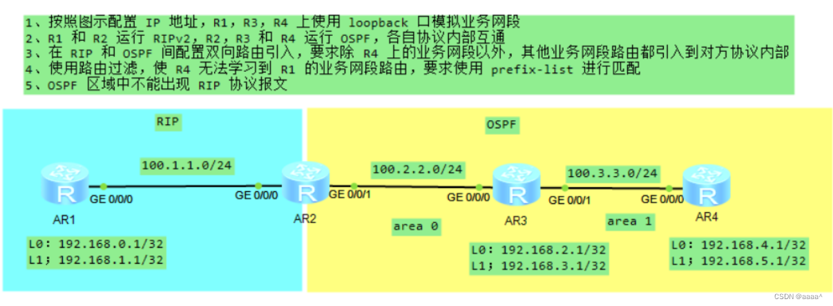
具体接口IP地址如下图所示
 第一步:配置IP
R1:
[R1]int g 0/0/0
[R1-GigabitEthernet0/0/0]ip ad
[R1-GigabitEthernet0/0/0]ip address 100.1.1.1 24
Apr 23 2024 19:35:38-08:00 R1 %%01IFNET/4/LINK_STATE(l)[0]:The line protocol IP
on the interface GigabitEthernet0/0/0 has entered the UP state.
[R1-GigabitEthernet0/0/0]qi
                            ^
Error:Incomplete command found at '^' position.
[R1-GigabitEthernet0/0/0]q
[R1]int l 0
[R1-LoopBack0]ip ad
[R1-LoopBack0]ip address 192.168.0.1 32
[R1-LoopBack0]q
[R1]int l 1
[R1-LoopBack1]ip ad
[R1-LoopBack1]ip address 192.168.1.1/32
                         ^
Error: Wrong parameter found at '^' position.
[R1-LoopBack1]ip address 192.168.1.1 32
[R1-LoopBack1]
R2:
[Huawei]sysname R2
[R2]int g 0/0/0
[R2-GigabitEthernet0/0/0]ip ad
[R2-GigabitEthernet0/0/0]ip address 100.1.1.2 24
Apr 23 2024 19:36:52-08:00 R2 %%01IFNET/4/LINK_STATE(l)[0]:The line protocol IP
on the interface GigabitEthernet0/0/0 has entered the UP state.
[R2-GigabitEthernet0/0/0]q
[R2]int g 0/0/1
[R2-GigabitEthernet0/0/1]ip ad
[R2-GigabitEthernet0/0/1]ip address 100.2.2.2 24
Apr 23 2024 19:37:14-08:00 R2 %%01IFNET/4/LINK_STATE(l)[1]:The line protocol IP
on the interface GigabitEthernet0/0/1 has entered the UP state.
[R2-GigabitEthernet0/0/1]q
[R2]
R3:
[R3]int g 0/0/0
[R3-GigabitEthernet0/0/0]ip ad
[R3-GigabitEthernet0/0/0]ip address 100.2.2.3 24
Apr 23 2024 19:37:51-08:00 R3 %%01IFNET/4/LINK_STATE(l)[0]:The line protocol IP
on the interface GigabitEthernet0/0/0 has entered the UP state.
[R3-GigabitEthernet0/0/0]q
[R3]int g 0/0/1
[R3-GigabitEthernet0/0/1]ip ad
[R3-GigabitEthernet0/0/1]ip address 100.3.3.3 24
Apr 23 2024 19:38:02-08:00 R3 %%01IFNET/4/LINK_STATE(l)[1]:The line protocol IP
on the interface GigabitEthernet0/0/1 has entered the UP state.
[R3-GigabitEthernet0/0/1]q
[R3]int l 0
[R3-LoopBack0]ip ad
[R3-LoopBack0]ip address 192.168.2.1 32
[R3-LoopBack0]q
[R3]int l 1
[R3-LoopBack1]ip ad
[R3-LoopBack1]ip address 192.168.3.1 32
[R3-LoopBack1]q
[R3]
R4:
[R4]int g 0/0/0
[R4-GigabitEthernet0/0/0]ip ad
[R4-GigabitEthernet0/0/0]ip address 100.3.3.4 24
Apr 23 2024 19:38:48-08:00 R4 %%01IFNET/4/LINK_STATE(l)[0]:The line protocol IP
on the interface GigabitEthernet0/0/0 has entered the UP state.
[R4-GigabitEthernet0/0/0]q
[R4]int l 0
[R4-LoopBack0]ip ad
[R4-LoopBack0]ip address 192.168.4.1 32
[R4-LoopBack0]q
[R4]int l 1
[R4-LoopBack1]ip ad
[R4-LoopBack1]ip address 192.168.5.1 32
[R4-LoopBack1]q
[R4]
第二步:配置RIP和OSPF
RIP
R1:
[R1]r
[R1]rip 1
[R1-rip-1]v 2
[R1-rip-1]undo s
[R1-rip-1]undo summary
[R1-rip-1]ne
[R1-rip-1]network 100.0.0.0
[R1-rip-1]ne
[R1-rip-1]network 192.168.0.0
[R1-rip-1]network 192.168.1.0
[R1-rip-1]
R2:
[R2]rip 1
[R2-rip-1]v 2
[R2-rip-1]und
[R2-rip-1]undo s
[R2-rip-1]undo su
[R2-rip-1]undo summary
[R2-rip-1]ne
[R2-rip-1]network 100.0.0.0
[R2-rip-1]q
[R2]
OSPF
R2:
[R2]os
[R2]ospf 1 rou
[R2]ospf 1 router-id 2.2.2.2
[R2-ospf-1]a 0
[R2-ospf-1-area-0.0.0.0]ne
[R2-ospf-1-area-0.0.0.0]network 100.2.2.0 0.0.0.255
[R2-ospf-1-area-0.0.0.0]
R3:
[R3]os
[R3]ospf 1 rou
[R3]ospf 1 router-id 3.3.3.3
[R3-ospf-1]a 0
[R3-ospf-1-area-0.0.0.0]ne
[R3-ospf-1-area-0.0.0.0]network 100.2.2.0 0.0.0.255
[R3-ospf-1-area-0.0.0.0]network 192.168.2.1 0.0.0.0
[R3-ospf-1-area-0.0.0.0]network 192.168.3.1 0.0.0.0
[R3-ospf-1-area-0.0.0.0]
[R3-ospf-1]a 1
[R3-ospf-1-area-0.0.0.1]ne
[R3-ospf-1-area-0.0.0.1]network 100.3.3.0 0.0.0.255
[R3-ospf-1-area-0.0.0.1]q
[R3-ospf-1]
R4:
[R4]os
[R4]ospf 1 r
[R4]ospf 1 router-id 4.4.4.4
[R4-ospf-1]a 1
[R4-ospf-1-area-0.0.0.1]ne
[R4-ospf-1-area-0.0.0.1]network 100.3.3.0 0.0.0.255
[R4-ospf-1-area-0.0.0.1]
[R4-ospf-1-area-0.0.0.1]ne
[R4-ospf-1-area-0.0.0.1]network 192.168.4.1 0.0.0.0
[R4-ospf-1-area-0.0.0.1]network 192.168.5.1 0.0.0.0
[R4-ospf-1-area-0.0.0.1]
第三步:进行路由引入,屏蔽掉R4的网段
先引入
R2:
[R2]os
[R2]ospf 1
[R2-ospf-1]im
[R2-ospf-1]import-route rip
[R2-ospf-1]import-route rip 1
[R2-ospf-1]q
[R2]rip 1
[R2-rip-1]im
[R2-rip-1]import-route os
[R2-rip-1]import-route ospf 1
[R2-rip-1]q
[R2]
再进行
[R2]ac
[R2]acl 2000
[R2-acl-basic-2000]ru
[R2-acl-basic-2000]rule de
[R2-acl-basic-2000]rule deny s
[R2-acl-basic-2000]rule deny source 192.168.4.0 0.0.1.255
[R2-acl-basic-2000]ri
[R2-acl-basic-2000]ru
[R2-acl-basic-2000]rule p
[R2-acl-basic-2000]rule permit s
[R2-acl-basic-2000]rule permit source 0.0.0.0 255.255.255.255
[R2-acl-basic-2000]q
[R2]rou
[R2]route-po
[R2]route-policy aa pr
[R2]route-policy aa pe
[R2]route-policy aa permit no
[R2]route-policy aa permit node 10
Info: New Sequence of this List.
[R2-route-policy]if
[R2-route-policy]if-match a
[R2-route-policy]if-match acl 2000
[R2-route-policy]q
[R2]rip 1
[R2-rip-1]im
[R2-rip-1]import-route os
[R2-rip-1]import-route ospf 1 rou
[R2-rip-1]import-route ospf 1 route-policy aa
[R2-rip-1]q
[R2]
第四步:使用过滤让R4无法学习到R1的业务网段路由
R4:
<R4>sys
Enter system view, return user view with Ctrl+Z.
[R4]ip ip
[R4]ip ip-prefix aa in
[R4]ip ip-prefix aa index 10 de
[R4]ip ip-prefix aa index 10 deny 192.168.0.0 23 l
[R4]ip ip-prefix aa index 10 deny 192.168.0.0 23 less-equal 32
[R4]ip ip
[R4]ip ip-prefix aa in
[R4]ip ip-prefix aa index 20 pr
[R4]ip ip-prefix aa index 20 pe
[R4]ip ip-prefix aa index 20 permit 0.0.0.0 0 l
[R4]ip ip-prefix aa index 20 permit 0.0.0.0 0 less-equal 32
[R4]os
[R4]ospf 1
[R4-ospf-1]fi
[R4-ospf-1]filter-policy ip
[R4-ospf-1]filter-policy ip-prefix aa im
[R4-ospf-1]filter-policy ip-prefix aa import
[R4-ospf-1]q
[R4]
[R4]
第五步:使OSPF区域不出现RIP报文
R2:
[R2]rip 1
[R2-rip-1]si
[R2-rip-1]silent-interface g
[R2-rip-1]silent-interface GigabitEthernet 0/0/1
[R2-rip-1]q
[R2]