一、拓扑图
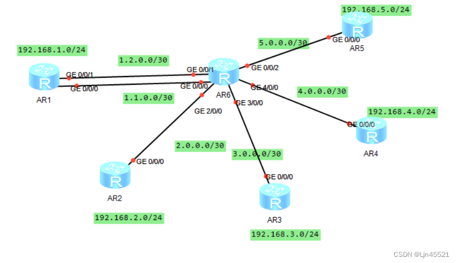
二、实验内容
1,R6为ISP只能配置IP地址,R1-R5的环回为私有网段
2,R1/4/5为全连的MGRE结构,R1/2/3为星型的拓扑结构,R1为中心站点
3,所有私有网段可以互相通讯,私有网段使用OSPF完成
三、实验步骤
1.配置IP
R1
[r1]int g 0/0/0
[r1-GigabitEthernet0/0/0]ip add 1.1.0.1 30
Apr 16 2024 15:48:13-08:00 r1 %%01IFNET/4/LINK_STATE(l)[0]:The line protocol IP
on the interface GigabitEthernet0/0/0 has entered the UP state.
[r1-GigabitEthernet0/0/0]int g 0/0/1
[r1-GigabitEthernet0/0/1]ip add 1.2.0.1 30
Apr 16 2024 15:48:42-08:00 r1 %%01IFNET/4/LINK_STATE(l)[1]:The line protocol IP
on the interface GigabitEthernet0/0/1 has entered the UP state.
[r1-GigabitEthernet0/0/1]int l 0
[r1-LoopBack0]ip add 192.168.1.1 24
[r1-LoopBack0]q
R2
[r2]int g 0/0/0
[r2-GigabitEthernet0/0/0]ip add 2.0.0.1 30
Apr 16 2024 15:50:36-08:00 r2 %%01IFNET/4/LINK_STATE(l)[0]:The line protocol IP
on the interface GigabitEthernet0/0/0 has entered the UP state.
[r2-GigabitEthernet0/0/0]int l 0
[r2-LoopBack0]ip add 192.168.2.1 24
[r2-LoopBack0]q
R3
[r3]int g 0/0/0
[r3-GigabitEthernet0/0/0]ip add 3.0.0.1 30
Apr 16 2024 15:52:11-08:00 r3 %%01IFNET/4/LINK_STATE(l)[0]:The line protocol IP
on the interface GigabitEthernet0/0/0 has entered the UP state.
[r3-GigabitEthernet0/0/0]int l 0
[r3-LoopBack0]ip add 192.168.3.1 24
[r3-LoopBack0]q
R4
[r4]int g 0/0/0
[r4-GigabitEthernet0/0/0]ip add 4.0.0.1 30
[r4-GigabitEthernet0/0/0]
Apr 16 2024 15:53:00-08:00 r4 %%01IFNET/4/LINK_STATE(l)[0]:The line protocol IP
on the interface GigabitEthernet0/0/0 has entered the UP state.
[r4-GigabitEthernet0/0/0]int l 0
[r4-LoopBack0]ip add 192.168.4.1 24
R5
[r5]int g 0/0/0
[r5-GigabitEthernet0/0/0]ip add 5.0.0.1 30
Apr 16 2024 15:53:45-08:00 r5 %%01IFNET/4/LINK_STATE(l)[0]:The line protocol IP
on the interface GigabitEthernet0/0/0 has entered the UP state.
[r5-GigabitEthernet0/0/0]int l 0
[r5-LoopBack0]ip add 192.168.5.1 24
R6
[r6]int g 0/0/1
[r6-GigabitEthernet0/0/1]ip add 1.2.0.2 30
Apr 16 2024 15:54:54-08:00 r6 %%01IFNET/4/LINK_STATE(l)[0]:The line protocol IP
on the interface GigabitEthernet0/0/1 has entered the UP state.
[r6-GigabitEthernet0/0/1]int g 0/0/0
[r6-GigabitEthernet0/0/0]ip add 1.1.0.2 30
Apr 16 2024 15:55:14-08:00 r6 %%01IFNET/4/LINK_STATE(l)[1]:The line protocol IP
on the interface GigabitEthernet0/0/0 has entered the UP state.
[r6-GigabitEthernet0/0/0]int g 2/0/0
[r6-GigabitEthernet2/0/0]ip add 2.0.0.2 30
[r6-GigabitEthernet2/0/0]
Apr 16 2024 15:55:45-08:00 r6 %%01IFNET/4/LINK_STATE(l)[2]:The line protocol IP
on the interface GigabitEthernet2/0/0 has entered the UP state.
[r6-GigabitEthernet2/0/0]int g 3/0/0
[r6-GigabitEthernet3/0/0]ip add 3.0.0.2 30
[r6-GigabitEthernet3/0/0]
Apr 16 2024 15:56:07-08:00 r6 %%01IFNET/4/LINK_STATE(l)[3]:The line protocol IP
on the interface GigabitEthernet3/0/0 has entered the UP state.
[r6-GigabitEthernet3/0/0]int g 4/0/0
[r6-GigabitEthernet4/0/0]ip add 4.0.0.2 30
[r6-GigabitEthernet4/0/0]
Apr 16 2024 15:56:38-08:00 r6 %%01IFNET/4/LINK_STATE(l)[4]:The line protocol IP
on the interface GigabitEthernet4/0/0 has entered the UP state.
[r6-GigabitEthernet4/0/0]int g 0/0/2
[r6-GigabitEthernet0/0/2]ip add 5.0.0.2 30
[r6-GigabitEthernet0/0/2]
Apr 16 2024 15:57:01-08:00 r6 %%01IFNET/4/LINK_STATE(l)[5]:The line protocol IP
on the interface GigabitEthernet0/0/2 has entered the UP state.
[r6-GigabitEthernet0/0/2]q
2.配置指向公网的缺省路由
R1
[r1]ip route-static 0.0.0.0 0 1.2.0.2
[r1]ip route-static 0.0.0.0 0 1.1.0.2
R2
[r2]ip route-static 0.0.0.0 0 2.0.0.2
R3
[r3]ip route-static 0.0.0.0 0 3.0.0.2
R4
[r4]ip route-static 0.0.0.0 0 4.0.0.2
R5
[r5]ip route-static 0.0.0.0 0 5.0.0.2
3.做R1/4/5为全连的MGRE结构,隧道网段设置为192.168.7.0/24
R1
[r1]ip route-static 0.0.0.0 0 1.2.0.2
[r1]ip route-static 0.0.0.0 0 1.1.0.2
[r1]int t
[r1]int Tunnel 0/0/1
[r1-Tunnel0/0/1]ip
[r1-Tunnel0/0/1]ip a
[r1-Tunnel0/0/1]ip address 192.168.7.1 24
[r1-Tunnel0/0/1]tu
[r1-Tunnel0/0/1]tunnel-protocol gre p
[r1-Tunnel0/0/1]tunnel-protocol gre p2mp
[r1-Tunnel0/0/1]sou
[r1-Tunnel0/0/1]source 1.2.0.1
Apr 16 2024 16:03:45-08:00 r1 %%01IFNET/4/LINK_STATE(l)[0]:The line protocol IP
on the interface Tunnel0/0/1 has entered the UP state.
[r1-Tunnel0/0/1]
[r1-Tunnel0/0/1]nhrp n
[r1-Tunnel0/0/1]nhrp network-id 101
[r1-Tunnel0/0/1]nhrp ne
[r1-Tunnel0/0/1]nhrp en
[r1-Tunnel0/0/1]nhrp entry 192.168.7.2 4.0.0.1 r
[r1-Tunnel0/0/1]nhrp entry 192.168.7.2 4.0.0.1 register
[r1-Tunnel0/0/1]nhrp entry 192.168.7.3 5.0.0.1 register
[r1-Tunnel0/0/1]q
R4
[r4]ip route-static 0.0.0.0 0 4.0.0.2
[r4]int t
[r4]int Tunnel 0/0/1
[r4-Tunnel0/0/1]ip add
[r4-Tunnel0/0/1]ip address 192.168.7.2 24
[r4-Tunnel0/0/1]t
[r4-Tunnel0/0/1]tu
[r4-Tunnel0/0/1]tunnel-protocol g
[r4-Tunnel0/0/1]tunnel-protocol gre p2mp
[r4-Tunnel0/0/1]sou
[r4-Tunnel0/0/1]source 4.0.0.1
Apr 16 2024 16:05:56-08:00 r4 %%01IFNET/4/LINK_STATE(l)[0]:The line protocol IP
on the interface Tunnel0/0/1 has entered the UP state.
[r4-Tunnel0/0/1]
[r4-Tunnel0/0/1]nhrp ne
[r4-Tunnel0/0/1]nhrp network-id 101
[r4-Tunnel0/0/1]nhrp entry 192.168.7.1 1.2.0.1 register
[r4-Tunnel0/0/1]nhrp entry 192.168.7.3 5.0.0.1 register
[r4-Tunnel0/0/1]
[r4-Tunnel0/0/1]q
R5
[r5]int Tunnel 0/0/1
[r5-Tunnel0/0/1]ip add 192.168.7.3 24
[r5-Tunnel0/0/1]tunnel-protocol gre p2mp
[r5-Tunnel0/0/1]source 5.0.0.1
Apr 16 2024 16:07:35-08:00 r5 %%01IFNET/4/LINK_STATE(l)[0]:The line protocol IP
on the interface Tunnel0/0/1 has entered the UP state.
[r5-Tunnel0/0/1]
[r5-Tunnel0/0/1]nhrp network-id 101
[r5-Tunnel0/0/1]nhrp entry 192.168.7.1 1.2.0.1 register
[r5-Tunnel0/0/1]nhrp entry 192.168.7.2 4.0.0.1 register
Info: This peer protocol address conflicts with hub register peer protocol addre
ss.
4.
做R1/2/3为星型的拓扑结构,使R1为中心站点
R1中心配置:隧道网段设置为192.168.6.0/24
[r1]int t
[r1]int Tunnel 0/0/0
[r1-Tunnel0/0/0]ip add
[r1-Tunnel0/0/0]ip address 192.168.6.1 24
[r1-Tunnel0/0/0]tu
[r1-Tunnel0/0/0]tunnel-protocol gre p
[r1-Tunnel0/0/0]tunnel-protocol gre p2mp
[r1-Tunnel0/0/0]nh
[r1-Tunnel0/0/0]nhrp net
[r1-Tunnel0/0/0]nhrp network-id 100
[r1-Tunnel0/0/0]nhrp en
[r1-Tunnel0/0/0]nhrp entry mu
[r1-Tunnel0/0/0]nhrp entry multicast dy
[r1-Tunnel0/0/0]nhrp entry multicast dynamic
[r1-Tunnel0/0/0]source
[r1-Tunnel0/0/0]source 1.1.0.1
Apr 16 2024 16:11:07-08:00 r1 %%01IFNET/4/LINK_STATE(l)[1]:The line protocol IP
on the interface Tunnel0/0/0 has entered the UP state.
[r1-Tunnel0/0/0]
[r1-Tunnel0/0/0]ospf net
[r1-Tunnel0/0/0]ospf network-type b
[r1-Tunnel0/0/0]ospf network-type broadcast
[r1-Tunnel0/0/0]q
R2、R3分支配置
R2
[r2]int t
[r2]int Tunnel 0/0/0
[r2-Tunnel0/0/0]ip add
[r2-Tunnel0/0/0]ip address 192.168.6.2 24
[r2-Tunnel0/0/0]tu
[r2-Tunnel0/0/0]tunnel-protocol gre p2mp
[r2-Tunnel0/0/0]source g 0/0/0
Apr 16 2024 16:13:03-08:00 r2 %%01IFNET/4/LINK_STATE(l)[0]:The line protocol IP
on the interface Tunnel0/0/0 has entered the UP state.
[r2-Tunnel0/0/0]
[r2-Tunnel0/0/0]nhrp network-id 100
[r2-Tunnel0/0/0]nhrp entry 192.168.6.1 1.1.0.1 register
[r2-Tunnel0/0/0]ospf network-type broadcast
R3
[r3]int Tunnel 0/0/0
[r3-Tunnel0/0/0]ip address 192.168.6.3 24
[r3-Tunnel0/0/0]tunnel-protocol gre p2mp
[r3-Tunnel0/0/0]source g 0/0/0
Apr 16 2024 16:14:11-08:00 r3 %%01IFNET/4/LINK_STATE(l)[0]:The line protocol IP
on the interface Tunnel0/0/0 has entered the UP state.
[r3-Tunnel0/0/0]
[r3-Tunnel0/0/0]nhrp network-id 100
[r3-Tunnel0/0/0]nhrp entry 192.168.6.1 1.1.0.1 register
[r3-Tunnel0/0/0]ospf network-type broadcast
5.启用ospf
[r1]ospf r
[r1]ospf router-id 1.1.1.1
[r1-ospf-1]a
[r1-ospf-1]area 0
[r1-ospf-1-area-0.0.0.0]net
[r1-ospf-1-area-0.0.0.0]network 192.168.1.0 0.0.0.0
[r1-ospf-1-area-0.0.0.0]network 192.168.6.0 0.0.0.255
[r1-ospf-1-area-0.0.0.0]network 192.168.7.0 0.0.0.255
R2
[r2]ospf rou
[r2]ospf router-id 2.2.2.2
[r2-ospf-1]a
[r2-ospf-1]area 0
[r2-ospf-1-area-0.0.0.0]net
[r2-ospf-1-area-0.0.0.0]network 192.168.2.0 0.0.0.255
[r2-ospf-1-area-0.0.0.0]network 192.168.6.0 0.0.0.255
[r2-ospf-1-area-0.0.0.0]q
R3
[r3]ospf rou
[r3]ospf router-id 3.3.3.3
Info: The configuration succeeded. You need to restart the OSPF process to valid
ate the new router ID.
[r3-ospf-1]are
[r3-ospf-1]area 0
[r3-ospf-1-area-0.0.0.0]net
[r3-ospf-1-area-0.0.0.0]network 192.168.3.0 0.0.0.255
[r3-ospf-1-area-0.0.0.0]network 192.168.6.0 0.0.0.255
[r3-ospf-1-area-0.0.0.0]
R4
[r4]ospf rou
[r4]ospf router-id 4.4.4.4
[r4-ospf-1]ar
[r4-ospf-1]area 0
[r4-ospf-1-area-0.0.0.0]net
[r4-ospf-1-area-0.0.0.0]network 192.168.4.0 0.0.0.255
[r4-ospf-1-area-0.0.0.0]network 192.168.7.0 0.0.0.255
[r4-ospf-1-area-0.0.0.0]
R5
[r5]ospf rou
[r5]ospf router-id 5.5.5.5
[r5-ospf-1]ar
[r5-ospf-1]area 0
[r5-ospf-1-area-0.0.0.0]net
[r5-ospf-1-area-0.0.0.0]network 192.168.5.0 0.0.0.255
[r5-ospf-1-area-0.0.0.0]network 192.168.7.0 0.0.0.255
[r5-ospf-1-area-0.0.0.0]q
[r5-ospf-1]
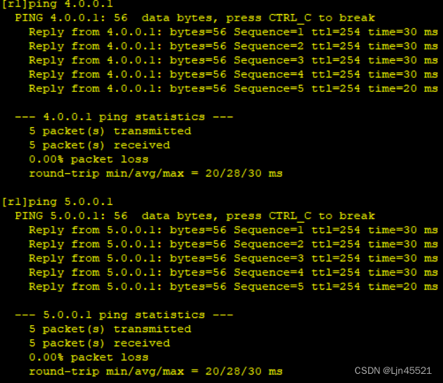
6.ping通验证
