从局域网去往广域网的流量有时需要进行分流,即区别了不同用户又进行了负载分担,有时这种目标是通过对不同的源地址进行区别对待完成的,通过策略路由的方法可以解决此问题。
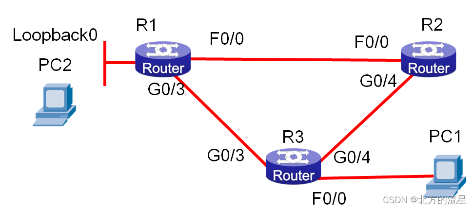
实验拓扑图如下所示
| R1 | R2 | R3 | |||
| F0/0 | 1.1.3.1/24 | F0/0 | 1.1.3.2/24 | G0/4 | 1.1.5.2/24 |
| G0/3 | 1.1.2.1/24 | G0/4 | 1.1.5.1/24 | G0/3 | 1.1.2.2/24 |
| loopback0 | 1.1.1.1/24 | F0/0 | 1.1.4.1/24 | ||
任务要求:配置基础网络环境,全网使用OSPF单区域完成路由的连通,在R3中使用策略路由,使来自1.1.4.10的源地址去往外网的路由从1.1.2.1走,而来自1.1.4.20的源地址的数据从1.1.5.2的路径走。跟踪从1.1.4.10去往1.1.1.10的数据路由。将1.1.4.10地址改为1.1.4.20,再次跟踪路由。使用R1设备上的loopback0口模拟PC2。
操作步骤:
步骤1:配置路由器R1基础网络环境。
Router_config#hostname R1
R1_config#interface fastEthernet 0/0
R1_config_f0/0#ip address 1.1.3.1 255.255.255.0
R1_config_f0/0#no shutdown
R1_config_f0/0#exit
R1_config#interface gigaEthernet 0/3
R1_config_g0/3#ip address 1.1.2.1 255.255.255.0
R1_config_g0/3#no shutdown
R1_config_g0/3#exit
R1_config#interface loopback 0
R1_config_l0#ip address 1.1.1.1 255.255.255.0
步骤2:配置路由器R2基础网络环境。
Router_config#hostname R2
R2_config#interface fastEthernet 0/0
R2_config_f0/0#ip address 1.1.3.2 255.255.255.0
R2_config_f0/0# no shutdown
R2_config_f0/0#exit
R2_config#interface gigaEthernet 0/4
R2_config_g0/3#ip address 1.1.5.1 255.255.255.0
R2_config_g0/3# no shutdown
R2_config_g0/3#exit
步骤3:配置路由器R3基础网络环境。
Router_config#hostname R3
R3_config#interface gastEthernet 0/3
R3_config_f0/0#ip address 1.1.2.2 255.255.255.0
R3_config_f0/0# no shutdown
R3_config_f0/0#exit
R3_config#interface fastEthernet 0/0
R3_config_f0/0#ip address 1.1.4.1 255.255.255.0
R3_config_f0/0# no shutdown
R3_config_f0/0#exit
R3_config#interface gastEthernet 0/4
R3_config_g0/4#ip address 1.1.5.2 255.255.255.0
R3_config_g0/4# no shutdown
步骤4:测试R2链路连通性。
R2#ping 1.1.3.1
PING 1.1.3.1 (1.1.3.1): 56 data bytes
!!!!!
--- 1.1.3.1 ping statistics ---
5 packets transmitted, 5 packets received, 0% packet loss
round-trip min/avg/max = 0/0/0 ms
R2#ping 1.1.5.2
PING 1.1.5.2 (1.1.5.2): 56 data bytes
!!!!!
--- 1.1.5.2 ping statistics ---
5 packets transmitted, 5 packets received, 0% packet loss
round-trip min/avg/max = 0/0/0 ms
R2#
步骤5:测试R3链路连通性。
R3#ping 1.1.2.1
PING 1.1.2.1 (1.1.2.1): 56 data bytes
!!!!!
--- 1.1.2.1 ping statistics ---
5 packets transmitted, 5 packets received, 0% packet loss
round-trip min/avg/max = 0/0/0 ms
表示单条链路都可以连通。
步骤6:配置R1路由环境,使用OSPF单区域配置。
R1_config#router ospf 1
R1_config_ospf_1#network 1.1.3.0 255.255.255.0 area 0
R1_config_ospf_1#network 1.1.2.0 255.255.255.0 area 0
R1_config_ospf_1#redistribute connect
R1_config_ospf_1#exit
步骤7:配置R2路由环境,使用OSPF单区域配置。
R2_config#router ospf 1
R2_config_ospf_1#network 1.1.3.0 255.255.255.0 area 0
R2_config_ospf_1#network 1.1.5.0 255.255.255.0 area 0
R2_config_ospf_1#redistribute connect
R2_config_ospf_1#exit
步骤8:配置R3路由环境,使用OSPF单区域配置。
R3_config#router ospf 1
R3_config_ospf_1#network 1.1.2.0 255.255.255.0 area 0
R3_config_ospf_1#network 1.1.5.0 255.255.255.0 area 0
R3_config_ospf_1#redistribute connect
R3_config_ospf_1#exit
步骤9:查看R1路由表。
R1#sh ip route
C 1.1.1.0/24 is directly connected, Loopback0
C 1.1.2.0/24 is directly connected, FastEthernet0/3
C 1.1.3.0/24 is directly connected, FastEthernet0/0
O E2 1.1.4.0/24 [150,100] via 1.1.2.2(on FastEthernet0/3)
O 1.1.5.0/24 [110,1601] via 1.1.2.2(on FastEthernet0/3)
步骤10:查看R2路由表。
R2#sh ip route
O E2 1.1.1.0/24 [150,100] via 1.1.3.1(on FastEthernet0/0)
O 1.1.2.0/24 [110,2] via 1.1.3.1(on FastEthernet0/0)
C 1.1.3.0/24 is directly connected, FastEthernet0/0
O E2 1.1.4.0/24 [150,100] via 1.1.3.1(on FastEthernet0/0)
C 1.1.5.0/24 is directly connected, Serial0/3
步骤11:查看R3路由表。
R3#sh ip route
O E2 1.1.1.0/24 [150,100] via 1.1.2.1(on FastEthernet0/0)
C 1.1.2.0/24 is directly connected, FastEthernet0/0
O 1.1.3.0/24 [110,2] via 1.1.2.1(on FastEthernet0/0)
C 1.1.4.0/24 is directly connected, FastEthernet0/3
C 1.1.5.0/24 is directly connected, Serial0/2
步骤12:在R3中使用策略路由。使来自1.1.4.10的源地址去往外网的路由从1.1.2.1走,而来自1.1.4.20的源地址的数据从1.1.5.1的路径走。
R3_config#ip access-list standard for_10
R3_config_std_nacl#permit 1.1.4.10
R3_config_std_nacl#exit
R3_config#ip access-list standard for_20
R3_config_std_nacl#permit 1.1.4.20
R3_config_std_nacl#exit
R3_config#route-map source_pbr 10 permit
R3_config_route_map#match ip address for_10
R3_config_route_map#set ip next-hop 1.1.2.1
R3_config_route_map#exit
R3_config#route-map source_pbr 20 permit
R3_config_route_map#match ip address for_20
R3_config_route_map#set ip next-hop 1.1.5.1
R3_config_route_map#exit
R3_config#interface fastEthernet 0/0
R3_config_f0/0#ip policy route-map source_pbr
R3_config_f0/0#
此时我们已经更改了R3的路由策略,从终端测试结果如下:
Settings\Administrator>ipconfig
Ethernet adapter 本地连接:
Connection-specific DNS Suffix . :
IP Address. . . . . . . . . . . . : 1.1.4.10
Subnet Mask . . . . . . . . . . . : 255.255.255.0
Default Gateway . . . . . . . . . : 1.1.4.1
C:\Documents and Settings\Administrator>tracert 1.1.1.1
Tracing route to 1.1.1.1 over a maximum of 30 hops
1 <1 ms<1 ms<1 ms 1.1.4.1
2 1 ms<1 ms<1 ms 1.1.1.1
C:\>ipconfig
Windows IP Configuration
Ethernet adapter 本地连接:
Connection-specific DNS Suffix . :
IP Address. . . . . . .. . : 1.1.4.20
Subnet Mask . . . . .. . . : 255.255.255.0
Default Gateway . . . . . : 1.1.4.1
C:\>tracert 1.1.1.1
Tracing route to 1.1.1.1 over a maximum of 30 hops
1 <1 ms<1 ms<1 ms 1.1.4.1
2 16 ms 15 ms 15 ms 1.1.5.1
3 15 ms 14 ms 15 ms 1.1.1.1
Trace complete.
可以看出,不同源的路由已经发生了改变。


