ZYNQ 7020显示 图片 实验
关键配置 BRAM
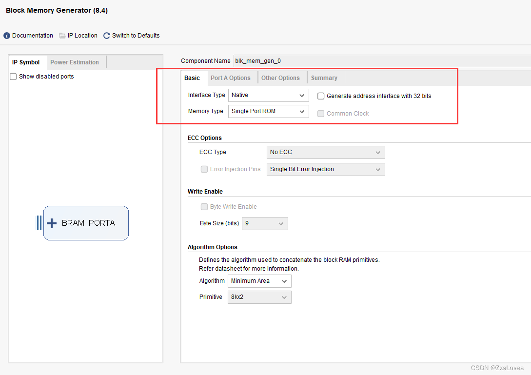
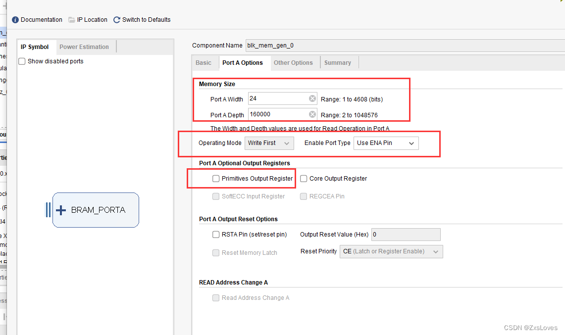
因为本次 我想显示的 图片是 400*400 所以在 内部 的 ROM 存储单元选择 了160000
ZYNQ7020的内部资源 最多是 大概 200000左右的 大小 大家可以根据 资源选择合适的像素

此处存放 内部的 图片转文字的COE文件
PLL设置
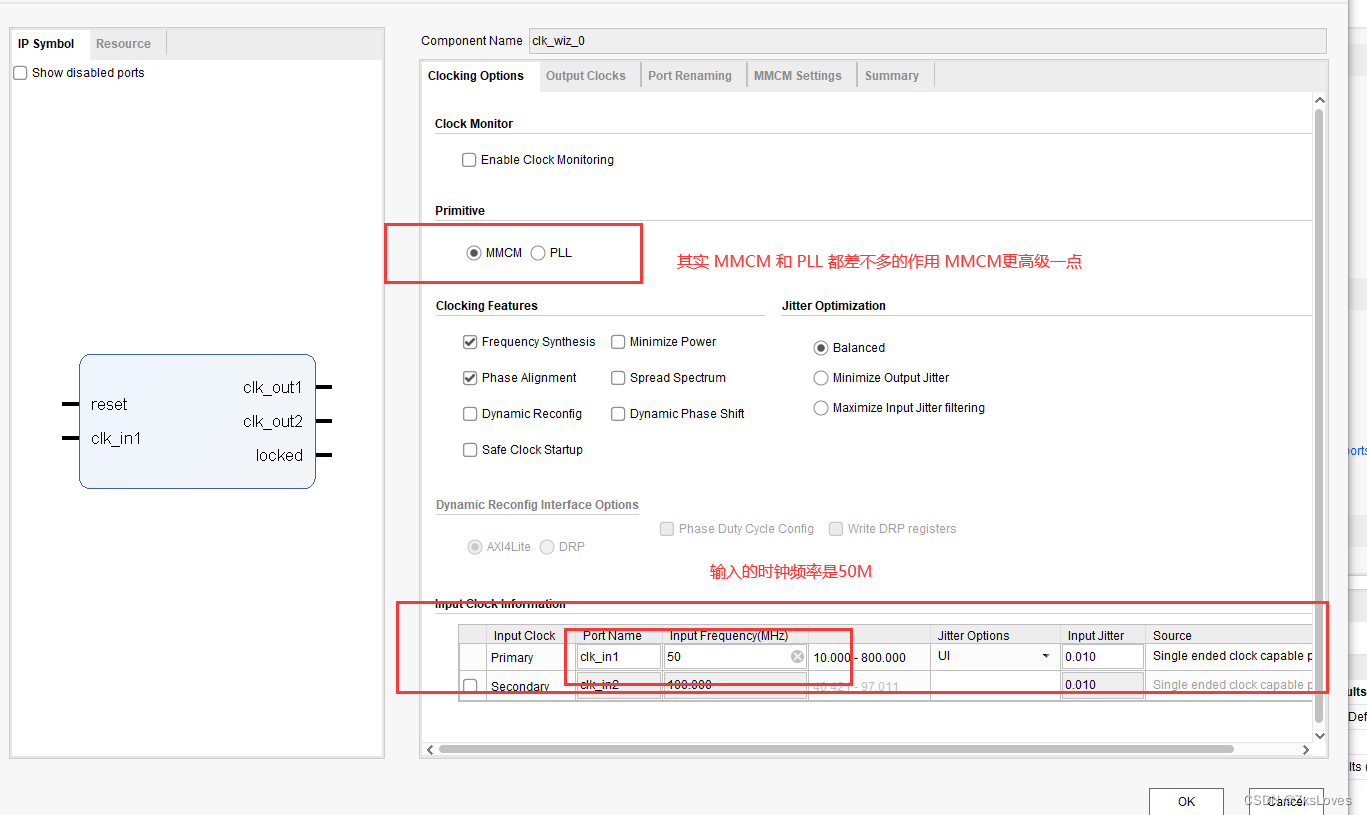
我选用的是按照720p 的 标准
之前准备做最大的1080P 发现 超出资源上限了

下面展示 整个的代码
注意 大部分代码 和 上一节是一样的
主要是 在显示 display 的时候 严格注意 宽度和高度 我一开始没设置对 出现了 图片显示 不正确的状况
dvi_transmitter_top.v
module dvi_transmitter_top(
    input                pclk          ,
    input                sys_rst_n     ,
    input                pclk_x5       ,
    input                video_hsync   ,
    input                video_vsync   ,
    input                video_de      ,
    input   [23 : 0]     video_din     ,
    output               tmds_clk_p    ,
    output               tmds_clk_n    ,
    output  [2 : 0]      tmds_data_p   ,
    output  [2 : 0]      tmds_data_n   ,
    output               tmds_oen
);


assign tmds_oen = 1 ;

// next is  define
wire  reset ;
wire [9:0] blue_10bit ;
wire [9:0] green_10bit ;
wire [9:0] red_10bit ;


wire [2:0] tmds_data_serial ;
wire       tmds_clk_serial  ;


reset_syn u_reset_syn(
    .pclk     ( pclk     ),
    .reset_n  ( sys_rst_n  ),
    .reset    ( reset    )
);


dvi_encoder u_dvi_encoder_blue(
    .clkin ( pclk ),
    .rstin ( reset ),
    .din   ( video_din[7:0]   ),
    .c0    ( video_hsync    ),
    .c1    ( video_vsync    ),
    .de    ( video_de    ),
    .dout  ( blue_10bit  )
);

dvi_encoder u_dvi_encoder_green(
    .clkin ( pclk ),
    .rstin ( reset ),
    .din   ( video_din[15:8]   ),
    .c0    ( 1'b0    ),
    .c1    ( 1'b0    ),
    .de    ( video_de    ),
    .dout  ( green_10bit  )
);


dvi_encoder u_dvi_encoder_red(
    .clkin ( pclk ),
    .rstin ( reset ),
    .din   ( video_din[23:16]   ),
    .c0    ( 1'b0    ),
    .c1    ( 1'b0    ),
    .de    ( video_de    ),
    .dout  ( red_10bit  )
);

serializer10 u_serializer10_blue(
    .reset          ( reset          ),
    .paralell_clk   ( pclk   ),
    .serial_clk_5x  ( pclk_x5  ),
    .paralell_data  ( blue_10bit  ),
    .serial_data_out  ( tmds_data_serial[0]  )
);

serializer10 u_serializer10_green(
    .reset          ( reset          ),
    .paralell_clk   ( pclk   ),
    .serial_clk_5x  ( pclk_x5  ),
    .paralell_data  ( green_10bit  ),
    .serial_data_out  ( tmds_data_serial[1]  )
);

serializer10 u_serializer10_red(
    .reset          ( reset          ),
    .paralell_clk   ( pclk   ),
    .serial_clk_5x  ( pclk_x5  ),
    .paralell_data  ( red_10bit  ),
    .serial_data_out  ( tmds_data_serial[2]  )
);

serializer10 u_serializer10_clk(
    .reset          ( reset          ),
    .paralell_clk   ( pclk   ),
    .serial_clk_5x  ( pclk_x5  ),
    .paralell_data  ( 10'b1111100000  ),
    .serial_data_out  ( tmds_clk_serial  )
);


//转换差分信号
OBUFDS #(
    .IOSTANDARD         ("TMDS_33")    // I/O电平标准为TMDS
) TMDS0 (
    .I                  (tmds_data_serial[0]),
    .O                  (tmds_data_p[0]),
    .OB                 (tmds_data_n[0])
);

OBUFDS #(
    .IOSTANDARD         ("TMDS_33")    // I/O电平标准为TMDS
) TMDS1 (
    .I                  (tmds_data_serial[1]),
    .O                  (tmds_data_p[1]),
    .OB                 (tmds_data_n[1])
);

OBUFDS #(
    .IOSTANDARD         ("TMDS_33")    // I/O电平标准为TMDS
) TMDS2 (
    .I                  (tmds_data_serial[2]),
    .O                  (tmds_data_p[2]),
    .OB                 (tmds_data_n[2])
);

OBUFDS #(
    .IOSTANDARD         ("TMDS_33")    // I/O电平标准为TMDS
) TMDS3 (
    .I                  (tmds_clk_serial),
    .O                  (tmds_clk_p),
    .OB                 (tmds_clk_n)
);
endmodule
encoder.v
module dvi_encoder (
  input            clkin,    // pixel clock input
  input            rstin,    // async. reset input (active high)
  input      [7:0] din,      // data inputs: expect registered
  input            c0,       // c0 input
  input            c1,       // c1 input
  input            de,       // de input
  output reg [9:0] dout      // data outputs
);


  // Counting number of 1s and 0s for each incoming pixel
  // component. Pipe line the result.
  // Register Data Input so it matches the pipe lined adder
  // output

  reg [3:0] n1d; //number of 1s in din
  reg [7:0] din_q;

//计算像素数据中“1”的个数
  always @ (posedge clkin) begin
    n1d <=#1 din[0] + din[1] + din[2] + din[3] + din[4] + din[5] + din[6] + din[7];

    din_q <=#1 din;
  end

  ///
  // Stage 1: 8 bit -> 9 bit
  // Refer to DVI 1.0 Specification, page 29, Figure 3-5
  ///
  wire decision1;

  assign decision1 = (n1d > 4'h4) | ((n1d == 4'h4) & (din_q[0] == 1'b0));

  wire [8:0] q_m;
  assign q_m[0] = din_q[0];
  assign q_m[1] = (decision1) ? (q_m[0] ^~ din_q[1]) : (q_m[0] ^ din_q[1]);
  assign q_m[2] = (decision1) ? (q_m[1] ^~ din_q[2]) : (q_m[1] ^ din_q[2]);
  assign q_m[3] = (decision1) ? (q_m[2] ^~ din_q[3]) : (q_m[2] ^ din_q[3]);
  assign q_m[4] = (decision1) ? (q_m[3] ^~ din_q[4]) : (q_m[3] ^ din_q[4]);
  assign q_m[5] = (decision1) ? (q_m[4] ^~ din_q[5]) : (q_m[4] ^ din_q[5]);
  assign q_m[6] = (decision1) ? (q_m[5] ^~ din_q[6]) : (q_m[5] ^ din_q[6]);
  assign q_m[7] = (decision1) ? (q_m[6] ^~ din_q[7]) : (q_m[6] ^ din_q[7]);
  assign q_m[8] = (decision1) ? 1'b0 : 1'b1;

  /
  // Stage 2: 9 bit -> 10 bit
  // Refer to DVI 1.0 Specification, page 29, Figure 3-5
  /
  reg [3:0] n1q_m, n0q_m; // number of 1s and 0s for q_m
  always @ (posedge clkin) begin
    n1q_m  <=#1 q_m[0] + q_m[1] + q_m[2] + q_m[3] + q_m[4] + q_m[5] + q_m[6] + q_m[7];
    n0q_m  <=#1 4'h8 - (q_m[0] + q_m[1] + q_m[2] + q_m[3] + q_m[4] + q_m[5] + q_m[6] + q_m[7]);
  end

  parameter CTRLTOKEN0 = 10'b1101010100;
  parameter CTRLTOKEN1 = 10'b0010101011;
  parameter CTRLTOKEN2 = 10'b0101010100;
  parameter CTRLTOKEN3 = 10'b1010101011;

  reg [4:0] cnt; //disparity counter, MSB is the sign bit
  wire decision2, decision3;

  assign decision2 = (cnt == 5'h0) | (n1q_m == n0q_m);
  /
  // [(cnt > 0) and (N1q_m > N0q_m)] or [(cnt < 0) and (N0q_m > N1q_m)]
  /
  assign decision3 = (~cnt[4] & (n1q_m > n0q_m)) | (cnt[4] & (n0q_m > n1q_m));


  // pipe line alignment

  reg       de_q, de_reg;
  reg       c0_q, c1_q;
  reg       c0_reg, c1_reg;
  reg [8:0] q_m_reg;

  always @ (posedge clkin) begin
    de_q    <=#1 de;
    de_reg  <=#1 de_q;

    c0_q    <=#1 c0;
    c0_reg  <=#1 c0_q;
    c1_q    <=#1 c1;
    c1_reg  <=#1 c1_q;

    q_m_reg <=#1 q_m;
  end

  ///
  // 10-bit out
  // disparity counter
  ///
  always @ (posedge clkin or posedge rstin) begin
    if(rstin) begin
      dout <= 10'h0;
      cnt <= 5'h0;
    end else begin
      if (de_reg) begin
        if(decision2) begin
          dout[9]   <=#1 ~q_m_reg[8];
          dout[8]   <=#1 q_m_reg[8];
          dout[7:0] <=#1 (q_m_reg[8]) ? q_m_reg[7:0] : ~q_m_reg[7:0];

          cnt <=#1 (~q_m_reg[8]) ? (cnt + n0q_m - n1q_m) : (cnt + n1q_m - n0q_m);
        end else begin
          if(decision3) begin
            dout[9]   <=#1 1'b1;
            dout[8]   <=#1 q_m_reg[8];
            dout[7:0] <=#1 ~q_m_reg[7:0];

            cnt <=#1 cnt + {q_m_reg[8], 1'b0} + (n0q_m - n1q_m);
          end else begin
            dout[9]   <=#1 1'b0;
            dout[8]   <=#1 q_m_reg[8];
            dout[7:0] <=#1 q_m_reg[7:0];

            cnt <=#1 cnt - {~q_m_reg[8], 1'b0} + (n1q_m - n0q_m);
          end
        end
      end else begin
        case ({c1_reg, c0_reg})
          2'b00:   dout <=#1 CTRLTOKEN0;
          2'b01:   dout <=#1 CTRLTOKEN1;
          2'b10:   dout <=#1 CTRLTOKEN2;
          default: dout <=#1 CTRLTOKEN3;
        endcase

        cnt <=#1 5'h0;
      end
    end
  end

endmodule
reset_syn.v
module  reset_syn(
    input            pclk     ,
    input            reset_n  ,
    output   reg     reset
  );

  reg reset1 ;


  always@( posedge pclk   or  negedge reset_n)
  begin
    if( reset_n == 0)
    begin
      reset1 <= 1 ;
    end
    else
    begin
      reset1 <= 0      ;
      reset  <= reset1 ;
    end
  end
endmodule
serializer.v
module serializer10 (
    input                       reset           ,  // 复位,高有效
    input                       paralell_clk    ,  // 输入并行数据时钟
    input                       serial_clk_5x   ,   // 输入串行数据时钟
    input        [9 : 0]        paralell_data   ,   // 输入并行数据
    output                      serial_data_out          // 输出串行数据
);


//wire define
 wire cascade1 ; //用于两个 OSERDESE2 级联的信号
 wire cascade2 ;


// 此处的代码 来自 vivado的 原语 和 正点原子的同时调配
// 这是 master接口


OSERDESE2 #(
    .DATA_RATE_OQ("DDR"),   // 设置双倍数据速率
    .DATA_RATE_TQ("DDR"),   // DDR, BUF, SDR
    .DATA_WIDTH(10),         // 输入的并行数据宽度为 10bit
   // .INIT_OQ(1'b0),         // Initial value of OQ output (1'b0,1'b1)
   // .INIT_TQ(1'b0),         // Initial value of TQ output (1'b0,1'b1)
    .SERDES_MODE("MASTER"), // MASTER, SLAVE
    //.SRVAL_OQ(1'b0),        // OQ output value when SR is used (1'b0,1'b1)
   // .SRVAL_TQ(1'b0),        // TQ output value when SR is used (1'b0,1'b1)
    .TBYTE_CTL("FALSE"),    // Enable tristate byte operation (FALSE, TRUE)
    .TBYTE_SRC("FALSE"),    // Tristate byte source (FALSE, TRUE)
    .TRISTATE_WIDTH(1)      // 3-state converter width (1,4)
 )
 OSERDESE2_MASTER (
    .OFB(),             // 未使用
    .OQ(serial_data_out),               // 串行输出数据
    // SHIFTOUT1 / SHIFTOUT2: 1-bit (each) output: Data output expansion (1-bit each)
    .SHIFTOUT1(),  // SHIFTIN1 用于位宽扩展
    .SHIFTOUT2(),  // SHIFTIN2 用于位宽扩展
    .TBYTEOUT(),   // 未使用
    .TFB(),             // 未使用
    .TQ(),               // 未使用
    .CLK(serial_clk_5x),    // 串行数据时钟,5 倍时钟频率
    .CLKDIV(paralell_clk),  // 并行数据时钟
    // D1 - D8: 1-bit (each) input: Parallel data inputs (1-bit each)
    .D1(paralell_data[0]),
    .D2(paralell_data[1]),
    .D3(paralell_data[2]),
    .D4(paralell_data[3]),
    .D5(paralell_data[4]),
    .D6(paralell_data[5]),
    .D7(paralell_data[6]),
    .D8(paralell_data[7]),
    .OCE(1'b1),             // 1-bit input: Output data clock enable
    .RST(reset),             // 1-bit input: Reset
    // SHIFTIN1 / SHIFTIN2: 1-bit (each) input: Data input expansion (1-bit each)
    .SHIFTIN1(cascade1),     // SHIFTIN1 用于位宽扩展
    .SHIFTIN2(cascade2),     // SHIFTIN2  用于位宽扩展
    // T1 - T4: 1-bit (each) input: Parallel 3-state inputs
    .T1(1'b0),                // 未使用
    .T2(1'b0),                // 未使用
    .T3(1'b0),                // 未使用
    .T4(1'b0),                // 未使用
    .TBYTEIN(1'b0),     // 未使用
    .TCE(1'b0)              // 未使用
 );


// slave接口
 OSERDESE2 #(
    .DATA_RATE_OQ("DDR"),   // 设置双倍数据速率
    .DATA_RATE_TQ("DDR"),   // DDR, BUF, SDR
    .DATA_WIDTH(10),         // 输入的并行数据宽度为 10bit
   // .INIT_OQ(1'b0),         // Initial value of OQ output (1'b0,1'b1)
   // .INIT_TQ(1'b0),         // Initial value of TQ output (1'b0,1'b1)
    .SERDES_MODE("SLAVE"), // MASTER, SLAVE
    //.SRVAL_OQ(1'b0),        // OQ output value when SR is used (1'b0,1'b1)
   // .SRVAL_TQ(1'b0),        // TQ output value when SR is used (1'b0,1'b1)
    .TBYTE_CTL("FALSE"),    // Enable tristate byte operation (FALSE, TRUE)
    .TBYTE_SRC("FALSE"),    // Tristate byte source (FALSE, TRUE)
    .TRISTATE_WIDTH(1)      // 3-state converter width (1,4)
 )
 OSERDESE2_SLAVE (
    .OFB(),             // 未使用
    .OQ(),               // 串行输出数据
    // SHIFTOUT1 / SHIFTOUT2: 1-bit (each) output: Data output expansion (1-bit each)
    .SHIFTOUT1(cascade1),  // SHIFTIN1 用于位宽扩展
    .SHIFTOUT2(cascade2),  // SHIFTIN2 用于位宽扩展
    .TBYTEOUT(),   // 未使用
    .TFB(),             // 未使用
    .TQ(),               // 未使用
    .CLK(serial_clk_5x),    // 串行数据时钟,5 倍时钟频率
    .CLKDIV(paralell_clk),  // 并行数据时钟
    // D1 - D8: 1-bit (each) input: Parallel data inputs (1-bit each)
    .D1(1'b0),
    .D2(1'b0),
    .D3(paralell_data[8]),
    .D4(paralell_data[9]),
    .D5(1'b0),
    .D6(1'b0),
    .D7(1'b0),
    .D8(1'b0),
    .OCE(1'b1),             // 1-bit input: Output data clock enable
    .RST(reset),             // 1-bit input: Reset
    // SHIFTIN1 / SHIFTIN2: 1-bit (each) input: Data input expansion (1-bit each)
    .SHIFTIN1(),     // SHIFTIN1 用于位宽扩展
    .SHIFTIN2(),     // SHIFTIN2  用于位宽扩展
    // T1 - T4: 1-bit (each) input: Parallel 3-state inputs
    .T1(1'b0),                // 未使用
    .T2(1'b0),                // 未使用
    .T3(1'b0),                // 未使用
    .T4(1'b0),                // 未使用
    .TBYTEIN(1'b0),     // 未使用
    .TCE(1'b0)              // 未使用
 );

endmodule
top.v
module hdmi_top(
    input        sys_clk,
    input        sys_rst_n,

    output       tmds_clk_p,    // TMDS 时钟通道
    output       tmds_clk_n,
    output [2:0] tmds_data_p,   // TMDS 数据通道
    output [2:0] tmds_data_n
  );

  //wire define
  wire          pixel_clk;
  wire          pixel_clk_5x;
  wire          clk_locked;

  wire  [10:0]  pixel_xpos_w;
  wire  [10:0]  pixel_ypos_w;
  wire  [23:0]  pixel_data_w;

  wire          video_hs;
  wire          video_vs;
  wire          video_de;
  wire  [23:0]  video_rgb;

  // next is main code
  clk_wiz_0 instance_name
            (
              // Clock out ports
              .clk_out1(pixel_clk),     // output clk_out1
              .clk_out2(pixel_clk_5x),     // output clk_out2
              // Status and control signals
              .reset(~sys_rst_n), // input reset
              .locked(clk_locked),       // output locked
              // Clock in ports
              .clk_in1(sys_clk)
              );

video_driver u_video_driver(
    .pixel_clk   ( pixel_clk   ),
    .rst_n       ( sys_rst_n       ),
    .pixel_data  ( pixel_data_w  ),
    .video_rgb   ( video_rgb   ),
    .video_hs    ( video_hs    ),
    .video_vs    ( video_vs    ),
    .video_de    ( video_de    ),
    .pixel_xpos  ( pixel_xpos_w  ),
    .pixel_ypos  ( pixel_ypos_w  )
);

video_display u_video_display(
    .pixel_clk     ( pixel_clk     ),
    .sys_rst_n     ( sys_rst_n     ),
    .pixel_xpos_w  ( pixel_xpos_w  ),
    .pixel_ypos_w  ( pixel_ypos_w  ),
    .pixel_data_w  ( pixel_data_w  )
);


dvi_transmitter_top u_dvi_transmitter_top(
    .pclk         ( pixel_clk         ),
    .sys_rst_n    ( sys_rst_n & clk_locked    ),
    .pclk_x5      ( pixel_clk_5x      ),
    .video_hsync  ( video_hs  ),
    .video_vsync  ( video_vs  ),
    .video_de     ( video_de     ),
    .video_din    ( video_rgb    ),
    .tmds_clk_p   ( tmds_clk_p   ),
    .tmds_clk_n   ( tmds_clk_n   ),
    .tmds_data_p  ( tmds_data_p  ),
    .tmds_data_n  ( tmds_data_n  ),
    .tmds_oen     ( )
);

endmodule
video_display.v
    module video_display(
    input                     pixel_clk       ,
    input                     sys_rst_n       ,
    input       [ 11 : 0 ]    pixel_xpos_w    ,
    input       [ 11 : 0 ]    pixel_ypos_w    ,
    output reg  [ 23 : 0 ]    pixel_data_w
  );


//parameter define
 localparam PIC_X_START = 11'd10; //图片起始点横坐标
 localparam PIC_Y_START = 11'd10; //图片起始点纵坐标
 localparam PIC_WIDTH = 11'd395; //图片宽度
 localparam PIC_HEIGHT = 11'd400; //图片高度


  //棰滆壊
  localparam BACK_COLOR  = 24'hE0FFFF; //背景色,浅蓝色
  localparam CHAR_COLOR  = 24'hff0000; //字符颜色,红色


  reg [19:0] rom_addr ; //ROM 地址
  wire rom_rd_en ; //ROM 读使能信号
  wire [23:0] rom_rd_data ;//ROM 数据


  always@( posedge pixel_clk or negedge sys_rst_n)
  begin
    if( sys_rst_n == 0)
    begin
      pixel_data_w <=BACK_COLOR ;
    end
    else if( (pixel_xpos_w >= PIC_X_START - 1'b1)
      && (pixel_xpos_w < PIC_X_START + PIC_WIDTH - 1'b1)
       && (pixel_ypos_w >= PIC_Y_START) && (pixel_ypos_w < PIC_Y_START + PIC_HEIGHT) )
       pixel_data_w <= rom_rd_data ; //显示图片
    else
      pixel_data_w <= BACK_COLOR ;
    end
 //根据当前扫描点的横纵坐标为ROM地址赋值
always @(posedge pixel_clk or negedge sys_rst_n) begin
  if(sys_rst_n == 0 )
      rom_addr <= 20'd0;
  //当横纵坐标位于图片显示区域时,累加ROM地址
  else if((pixel_ypos_w >= PIC_Y_START) && (pixel_ypos_w < PIC_Y_START + PIC_HEIGHT)
      && (pixel_xpos_w >= PIC_X_START) && (pixel_xpos_w < PIC_X_START + PIC_WIDTH))
      rom_addr <= rom_addr + 1'b1;
  //当横纵坐标位于图片区域最后一个像素点时,ROM地址清零
  else if((pixel_ypos_w >= PIC_Y_START + PIC_HEIGHT))
      rom_addr <= 20'd0;
end

//ROM:存储图片
blk_mem_gen_0  blk_mem_gen_0 (
.clka  (pixel_clk),    // input wire clka
.ena   (rom_rd_en),   // input wire ena
.addra (rom_addr),    // input wire [19 : 0] addra
.douta (rom_rd_data)  // output wire [23 : 0] douta
);


endmodule
video_driver.v
module video_driver
(
  input                         pixel_clk    ,
  input                         rst_n        ,
  input        [ 23 : 0 ]       pixel_data   ,

  output       [ 23 : 0 ]       video_rgb    ,
  output                        video_hs     ,     //  行同步信号
  output                        video_vs     ,     //  场同步信号
  output                        video_de     ,     //  数据使能
  output       [ 11 : 0 ]       pixel_xpos   ,     //  像素点横坐标  1280
  output       [ 11 : 0 ]       pixel_ypos        //  像素点横坐标  720
);

  //parameter define

  //1280*720  分辨率时序参数    时钟频率74.25
  parameter  H_SYNC   =  12'd40;   //行同步
  parameter  H_BACK   =  12'd220;  //行显示后沿
  parameter  H_DISP   =  12'd1280; //行有效数据
  parameter  H_FRONT  =  12'd110;  //行显示前沿
  parameter  H_TOTAL  =  12'd1650; //行扫描周期

  parameter  V_SYNC   =  12'd5;    //场同步
  parameter  V_BACK   =  12'd20;   //场显示后沿
  parameter  V_DISP   =  12'd720;  //场有效数据
  parameter  V_FRONT  =  12'd5;    //场显示前沿
  parameter  V_TOTAL  =  12'd750;  //场扫描周期


  //  reg define
  reg [11 : 0]   cnt_h ;
  reg [11 : 0]   cnt_v ;

 wire data_reg ;
  // define


  //  next is main code
  always@(posedge pixel_clk or negedge rst_n)
  begin
    if( rst_n == 0)
    begin
      cnt_h <= 0 ;
    end
    else
    begin
      if(cnt_h == H_TOTAL - 1)
      begin
        cnt_h <= 0 ;
      end
      else
        cnt_h <= cnt_h + 1 ;
    end
  end


  always@(posedge pixel_clk or negedge rst_n)
  begin
    if( rst_n == 0)
    begin
      cnt_v = 0 ;
    end
    else
    begin
      if( cnt_h == H_TOTAL - 1)
      begin
        if(cnt_v == V_TOTAL - 1)
        begin
          cnt_v <= 0 ;
        end
        else
        begin
          cnt_v <= cnt_v + 1 ;
        end
      end
    end
  end


//    =======================main code============\\
 // video_rgb
 // video_hs
 // video_vs
 // video_de
 // pixel_xpos
 // pixel_ypos
assign video_hs = 1 ;
assign video_vs = 1 ;

assign video_rgb  =   video_de ? pixel_data : 24'b0 ;

assign video_de   =  (((cnt_h >= H_SYNC+H_BACK) && (cnt_h < H_SYNC+H_BACK+H_DISP))
&&((cnt_v >= V_SYNC+V_BACK) && (cnt_v < V_SYNC+V_BACK+V_DISP)))
?  1'b1 : 1'b0;

assign data_reg   =  (((cnt_h >= H_SYNC+H_BACK - 1) && (cnt_h < H_SYNC+H_BACK+H_DISP - 1))
&&((cnt_v >= V_SYNC+V_BACK) && (cnt_v < V_SYNC+V_BACK+V_DISP)))
?  1'b1 : 1'b0;

assign pixel_xpos = data_reg ? (cnt_h - (H_SYNC + H_BACK - 1'b1)) : 0;
assign pixel_ypos = data_reg ? (cnt_v - (V_SYNC + V_BACK - 1'b1)) : 0;

endmodule






![[Linux] LVS负载均衡群集+NAT部署](https://img-blog.csdnimg.cn/direct/a460580f32f542acac50a370124c46e4.png)
