步骤1:配置PE和P设备的IGP以及mpls、mpls ldp(略)
步骤2:配置evpn实例,并且绑定到BD中,配置evpn的源ip地址
PE1:
evpn vpn-instance 1 bd-mode //指定创建BD模式EVPN实例
route-distinguisher 100:1
vpn-target 1:1 export-extcommunity
vpn-target 1:1 import-extcommunity
bridge-domain 10
evpn binding vpn-instance 1 //将BD域10绑定到evpn的BD模式实例中
evpn source-address 1.1.1.1 //指定evpn的源ip地址
PE2:
evpn vpn-instance 1 bd-mode
route-distinguisher 100:2
vpn-target 1:1 export-extcommunity
vpn-target 1:1 import-extcommunity
bridge-domain 10
evpn binding vpn-instance 1
evpn source-address 2.2.2.2
PE3:
evpn vpn-instance 1 bd-mode
route-distinguisher 100:3
vpn-target 1:1 export-extcommunity
vpn-target 1:1 import-extcommunity
evpn source-address 3.3.3.3
bridge-domain 10
evpn binding vpn-instance 1
步骤3:配置PE1和PE2的M-LAG
(1)CE双规侧配置 e-trunk ,绑定到eth-trunk中,做跨设备链路聚合。
PE1:
lacp e-trunk system-id 1111-1111-1111 //配置e-trunk的system id,两端需要一致
lacp e-trunk priority 1 //配置e-trunk的优先级
e-trunk 1
peer-address 2.2.2.2 source-address 1.1.1.1 //配置E-Trunk的对端设备地址为2.2.2.2,本端的IP地址为1.1.1.1
interface Eth-Trunk10 //创建聚合口
mode lacp-static //配置为lacp模式
e-trunk 1//绑定e-trunk
e-trunk mode force-master //设置前置为主动端
esi 0000.1111.1111.1111.1111 //配置连接CE链路的ESI,两端必须一致
PE2:
lacp e-trunk system-id 1111-1111-1111
lacp e-trunk priority 1
e-trunk 1
peer-address 1.1.1.1 source-address 2.2.2.2
interface Eth-Trunk10 //创建聚合口
mode lacp-static
e-trunk 1
esi 0000.1111.1111.1111.1111 //配置连接CE链路的ESI,两端必须一致
(2)创建eth-trunk子接口,模式改为L2,绑定到BD中,并且将物理接口绑定到eth-trunk 中
PE1:
interface Eth-Trunk10.1 mode l2//进入聚合口的子接口,模式改为2层模式
encapsulation dot1q vid 2 //指定二层子接口接收带指定802.1Q Tag封装的报文
rewrite pop single //配置EVC二层子接口的流动作是pop,对接收的报文进行剥除VLAN Tag操作
bridge-domain 10 //绑定BD域10
interface Ethernet1/0/0
eth-trunk 10 //将物理接口绑定到聚合口中
PE2:
interface Eth-Trunk10.1 mode l2
encapsulation dot1q vid 2
rewrite pop single
bridge-domain 10
interface Ethernet1/0/0
eth-trunk 10
(3)配置CE1的链路聚合
CE1:
Vlan 2
Int vlanif 2
Ip address 192.168.1.1 24
interface Eth-Trunk10
portswitch //配置接口为2层模式
port link-type trunk
port trunk allow-pass vlan 2
mode lacp-static
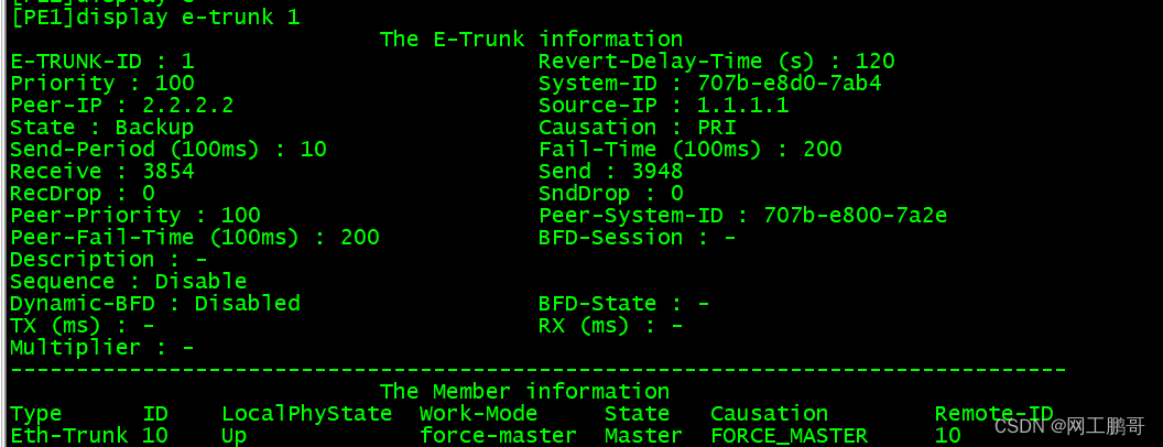
查看PE端的e-trunk的状态
查看CE的链路聚合状态

步骤4:配置PE3和CE2的互联接口
PE3:
interface Ethernet1/0/1.1 mode l2
encapsulation dot1q vid 2
rewrite pop single
bridge-domain 10
interface Ethernet1/0/1
esi 0000.2222.2222.2222.2222
CE2:
Vlan 2
interface Vlanif2
ip address 192.168.1.2 255.255.255.0
interface GigabitEthernet0/0/1
port link-type trunk
port trunk allow-pass vlan 2
步骤5:配置本端、远端MAC路由快速重路由功能。
PE1:
evpn
vlan-extend private enable
vlan-extend redirect enable
local-remote frr enable
PE2:
evpn
vlan-extend private enable
vlan-extend redirect enable
local-remote frr enable
PE3:
evpn
vlan-extend private enable
vlan-extend redirect enable
local-remote frr enable
步骤6:配置PE之间的Evpn邻居关系
PE1:
bgp 100
peer 2.2.2.2 as-number 100
peer 2.2.2.2 connect-interface LoopBack0
peer 3.3.3.3 as-number 100
peer 3.3.3.3 connect-interface LoopBack0
l2vpn-family evpn //进入二层evpn的地址族视图模式使能邻居关系
peer 2.2.2.2 enable
peer 3.3.3.3 enable
PE2:
bgp 100
peer 1.1.1.1 as-number 100
peer 1.1.1.1 connect-interface LoopBack0
peer 3.3.3.3 as-number 100
peer 3.3.3.3 connect-interface LoopBack0
l2vpn-family evpn
peer 1.1.1.1 enable
peer 3.3.3.3 enable
PE3:
bgp 100
peer 1.1.1.1 as-number 100
peer 1.1.1.1 connect-interface LoopBack0
peer 2.2.2.2 as-number 100
peer 2.2.2.2 connect-interface LoopBack0
l2vpn-family evpn
peer 1.1.1.1 enable
peer 2.2.2.2 enable
查看BGP的evpn邻居关系

测试CE之间的连通性:

下图为CE2学习到CE1的mac地址

通过几张evpn路由表来看下L2 evpn的工作过程:
启动阶段:
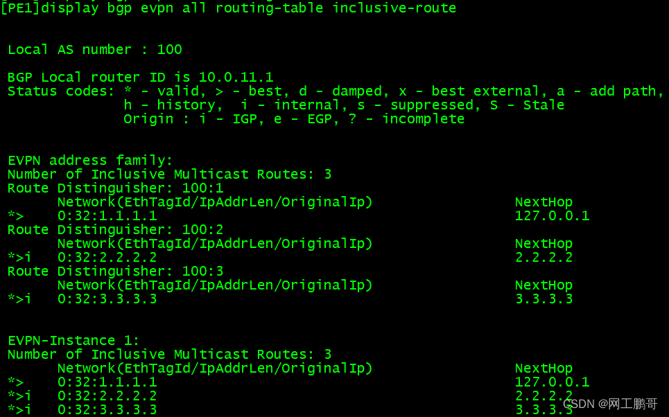
①PE之间建立MP-bgp的邻居关系,使用tpye3路由分配BUM流量标签,产生BUM流量转发表;(参考下图表示PE1收到BUM流量时,将流量泛洪给2.2.2.2和3.3.3.3)
查看其中一条的详细信息:

②PE设备交互type4路由,传递ESI信息,并且进行DF的选举(多归场景下面选举)
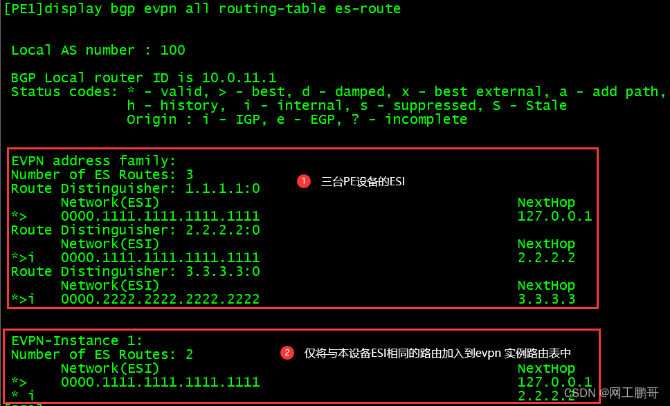
查看DF的选举结果:在PE1和PE2双归场景下,PE1被选举为DF,转发BUM流量。

③PE通过Type 1类路由分发ESI标签。ESI Label用于水平分割防止同一ES来的流量又绕回到该ES。(以PE1为例,PE1为将type1的路由发送给所有的邻居,携带 ESI 和所分配标签的对应关系)如果发送数据给相同的ESI设备时,会携带ESI标签,对端设备收到后,将不转发,实现水平分割。

流量转发阶段:
设备收到CE发送的arp请求报文,首先生成mac-vrf表项,然后向所有的邻居发送type2路由,为这个mac地址分配公网标签
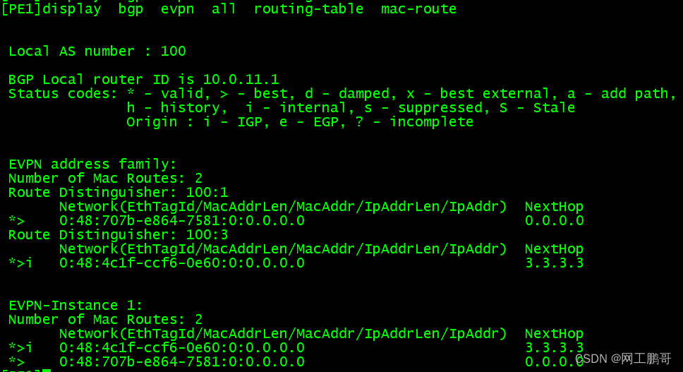
具体过程如下所示:
流量转发阶段:
1、设备收到CE发送的arp请求报文,首先生成mac-vrf表项,然后向所有的邻居发送type2路由,为这个mac地址分配公网标签
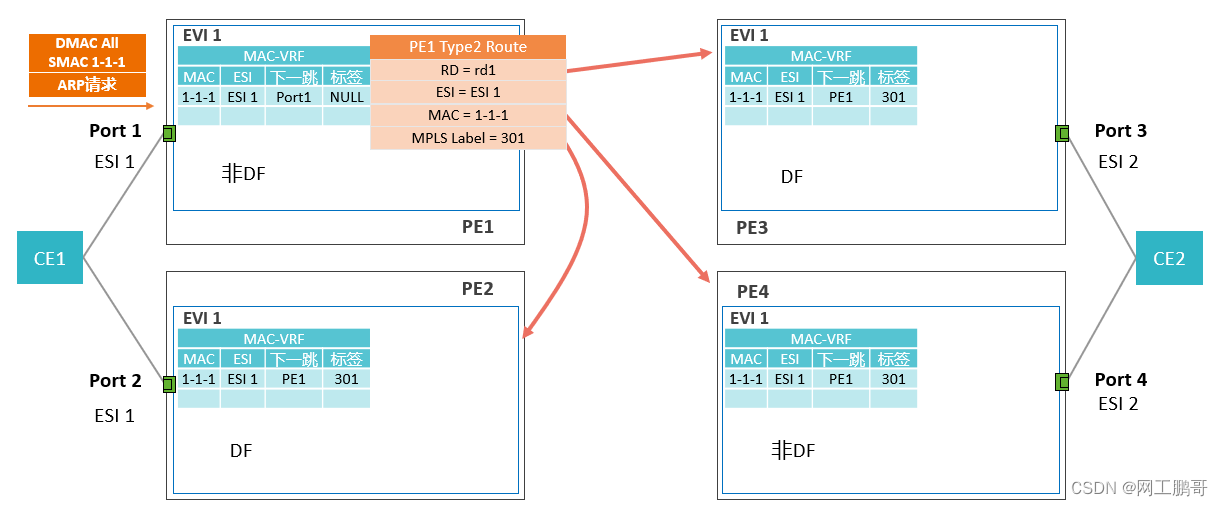
2、由于PE2直连ESI1,因此这个路由并不需要,E2会生成最优的mac地址表,指向port2,而不是PE1。
3、由于arp请求报文是一个广播报文,因此PE1收到广播报文后,会查询BUM流量转发表,将这个arp报文发送给所有的邻居,PE3、PE4收到之后会对应的mac地址表项,只有PE3会转发这个广播报文,因为PE3是DF 。
4、由于PE1和PE2属于相同ES,PE1到PE2的流量同时携带ESI标签202和BUM标签102。PE2接收到报文发现有标签202,则丢弃该报文。

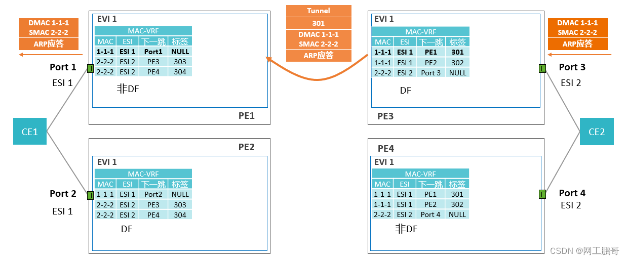
5、PE3生成并通告Type 2路由。其他PE接收PE3发出的Type 2路由(当设备产生新的mac地址表时就会发送type 2的路由告知邻居),刷新本地MAC表项。

6、PE3通过负载分担算法找出下一跳(如:PE1)发送报文,携带标签301。PE1接收报文后向Port1转发。

![[蓝桥复盘] 算法赛内测赛2 20230831](https://img-blog.csdnimg.cn/c6028a3fcb144c28aedf8f657d6ec321.png)
