全志RS485调试
思路:UART驱动中已经将485流控功能加进去了,所以我们只需要根据硬件原理图配置一下485脚的GPIO就行了。
硬件原理图:
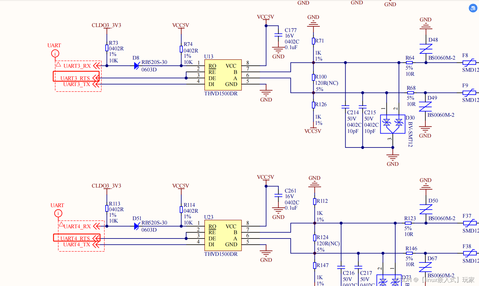
将UART3 UART4的RTS脚配置为485流控脚就行, RX和TX不需要配置,在pinctrol已经配置好了。
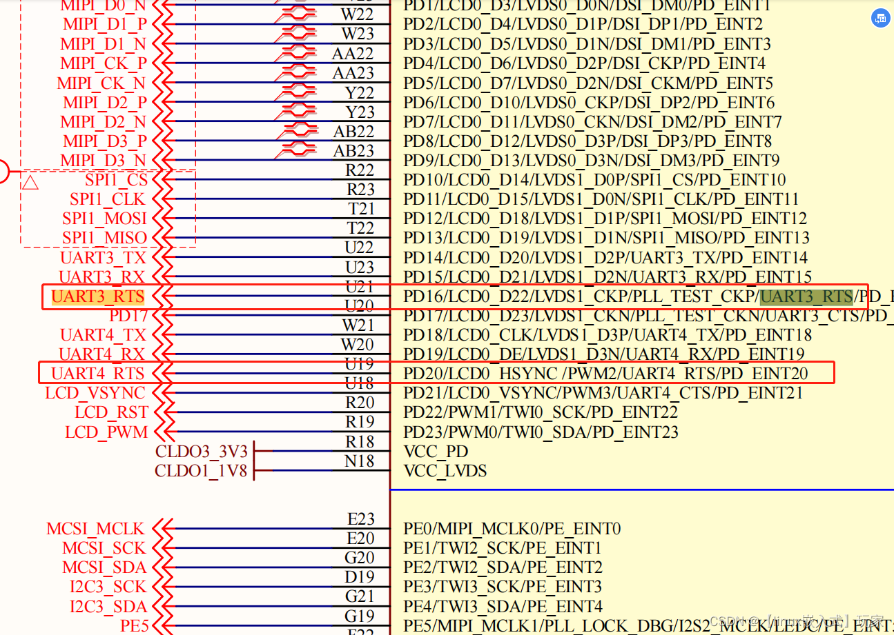
设备树修改:
        uart3: uart@05000c00 {
            rs485-en = <&pio PD 16 1 1 1 1>;
            status = "okay";
        };
        uart4: uart@05001000 {
            rs485-en = <&pio PD 20 1 1 1 1>;
            status = "okay";
        };
然后通过串口工具测试发现ok。UART3 UART4就这么简单配置好了。然后UART0卡了我很久,我们来看UART的配置:
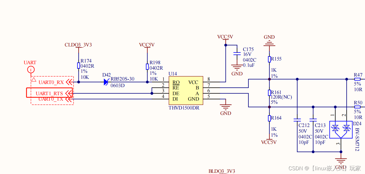
UART0的RTS脚为UART1_RTS,找到这个脚在主控中的PGIO号。
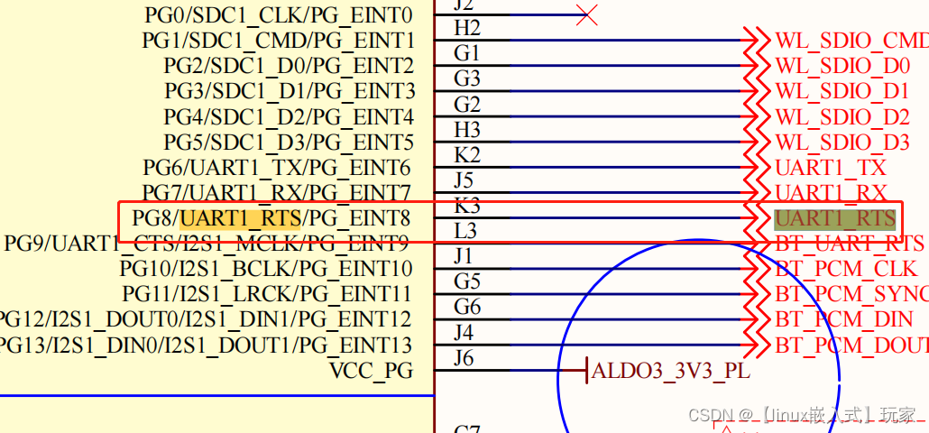
修改设备树:
uart0: uart@05000000 {
uart-supply = <®_bldo3>;
rs485-en = <&pio PG 8 1 1 1 1>;
status = "okay";
};
然后诡异的事情就发生了,当我配置完这个脚后,485只能发送不能接受,可是UART0和UART3 UART4的配置都差不多为什么会导致这样的情况呢?接下来就是漫长的debug了。。。。
首先我们用测量PG8的引脚发现为低电平,UART3 UART4的引脚为高电平这就奇怪了。我们去驱动加点打印信息看一下。
A133P:/ $
A133P:/ $ dmesg | grep lijie
[    1.082990] 3 lijie debug gpio_direction_output ok!
[    1.083005] uart uart0:  3 lijie debug sw_uport->rs485_gpio = 200 value = 0
[    1.083018] uart uart0:  x lijie debug sw_uport->rs485_gpio = 200 value = 0
[    1.085674] 3 lijie debug gpio_direction_output ok!
[    1.085687] uart uart3:  3 lijie debug sw_uport->rs485_gpio = 112 value = 0
[    1.085700] uart uart3:  x lijie debug sw_uport->rs485_gpio = 112 value = 0
[    1.086661] 3 lijie debug gpio_direction_output ok!
[    1.086674] uart uart4:  3 lijie debug sw_uport->rs485_gpio = 116 value = 0
[    1.086686] uart uart4:  x lijie debug sw_uport->rs485_gpio = 116 value = 0
A133P:/ $
我们发现驱动将485的gpio调为低电平默认接受状态。
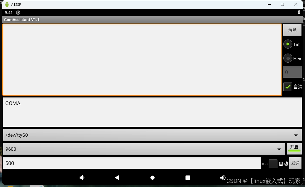
我们使用串口工具,打开UART0并且发送几条数据,再打开驱动调试信息看看
A133P:/ # dmesg | grep lijie
[    1.091874] 3 lijie debug gpio_direction_output ok!
[    1.091889] uart uart0:  3 lijie debug sw_uport->rs485_gpio = 200 value = 0
[    1.091902] uart uart0:  x lijie debug sw_uport->rs485_gpio = 200 value = 0
[    1.094525] 3 lijie debug gpio_direction_output ok!
[    1.094539] uart uart3:  3 lijie debug sw_uport->rs485_gpio = 112 value = 0
[    1.094551] uart uart3:  x lijie debug sw_uport->rs485_gpio = 112 value = 0
[    1.095534] 3 lijie debug gpio_direction_output ok!
[    1.095547] uart uart4:  3 lijie debug sw_uport->rs485_gpio = 116 value = 0
[    1.095559] uart uart4:  x lijie debug sw_uport->rs485_gpio = 116 value = 0
[   59.966164] 5 lijie debug sw_uport->rs485_gpio = 200 value = 1
[   59.970473] 1 lijie debug sw_uport->rs485_gpio = 200 value = 0
[   60.197280] 5 lijie debug sw_uport->rs485_gpio = 200 value = 1
[   60.201566] 1 lijie debug sw_uport->rs485_gpio = 200 value = 0
[   60.438232] 5 lijie debug sw_uport->rs485_gpio = 200 value = 1
[   60.442523] 1 lijie debug sw_uport->rs485_gpio = 200 value = 0
[   60.685118] 5 lijie debug sw_uport->rs485_gpio = 200 value = 1
[   60.689413] 1 lijie debug sw_uport->rs485_gpio = 200 value = 0
可以发现驱动在数据即将要发送的时候会将485的RTS拉高进入发送模式,当数据发送完毕就会拉低进入接收模式,这个逻辑说明驱动是没有问题的,但是我们用万用表测量发现UART0的485脚一直是高电平状态,根本就没有拉低过。
这就很奇怪,我们再看一下gpio的状态:
A133P:/sys/kernel/debug # cat gpio
gpiochip1: GPIOs 0-319, parent: platform/pio, pio:
 gpio-34  (                    |usbhub_rst          ) out hi
 gpio-38  (                    |touch_gpio_reset    ) out hi
 gpio-39  (                    |touch_gpio_irq      ) in  hi
 gpio-40  (                    |?                   ) in  hi
 gpio-106 (                    |cs-gpios            ) out hi
 gpio-112 (                    |RS485-EN            ) out lo
 gpio-116 (                    |RS485-EN            ) out lo
 gpio-118 (                    |?                   ) in  hi
 gpio-166 (                    |cd                  ) in  hi
 gpio-200 (                    |RS485-EN            ) out lo
 gpio-232 (                    |otg_id              ) in  hi
 gpio-235 (                    |?                   ) out hi
 gpio-236 (                    |phy-rst             ) out hi
 gpio-238 (                    |irq_gpio            ) in  hi
 gpio-240 (                    |mobile_pwr          ) out hi
 gpio-242 (                    |mobile_rst          ) out lo
 gpio-243 (                    |SPK                 ) out lo

gpiochip0: GPIOs 352-383, parent: platform/r_pio, r_pio:
 gpio-354 (                    |bt_rst              ) out lo
 gpio-357 (                    |wifi_bt_pwr         ) out hi
 gpio-360 (                    |usb1-vbus           ) out hi
PG8 = gpio 200 上面显示为485脚输出状态低电平,但是用万用表测试发现是高电平。。。。。这个时候就很无语了。。。。。。。
然后我就想手动拉低确定是不是GPIO号的问题:
mount -t debugfs debug /proc/sys/debug
cd /proc/sys/debug/sunxi_pinctrl
echo PH8 > sunxi_pin
echo PH6 1 > function
echo PH6 0 > data
这个是全志手动调试GPIO的方法,输入完上面的命令后,PG8应该为低电平,我们用万用表测试确实是低电平这说明GPIO号没有问题。驱动没有问题,GPIO号没有问题,UART0的485设备树没有问题,这就不知道是什么原因了。。。。。。。。。
后面发现,UART0的RTS脚为UART1_RTS,那UART1呢?

我们发现UART1 UART2就是普通的串口,然后我们去设备树看看这两个串口的配置信息。
 uart1_pins_a: uart1@0 {
        allwinner,pins = "PG6", "PG7", "PG8", "PG9";
        allwinner,pname = "uart1_tx", "uart1_rx",uart1_rts", "uart1_cts";
         allwinner,function = "uart1";
         allwinner,muxsel = <2>;
         allwinner,drive = <1>;
 };

 uart1_pins_b: uart1@1 {
        allwinner,pins = "PG6", "PG7", "PG8", "PG9";
        allwinner,function = "io_disabled";
        allwinner,muxsel = <7>;
        allwinner,drive = <1>;
        allwinner,pull = <1>;
};
看到这里就懂了,pinctrl中配置了UART1的rts和cts脚,但是硬件上面是不需要这两个脚的。
所以我们修改设备树
--- a/arch/arm64/boot/dts/sunxi/sun50iw10p1-pinctrl.dtsi
+++ b/arch/arm64/boot/dts/sunxi/sun50iw10p1-pinctrl.dtsi
@@ -133,9 +133,8 @@
                        };

                        uart1_pins_a: uart1@0 {
-                               allwinner,pins = "PG6", "PG7", "PG8", "PG9";
-                               allwinner,pname = "uart1_tx", "uart1_rx",
-                                                 "uart1_rts", "uart1_cts";
+                               allwinner,pins = "PG6", "PG7";
+                               allwinner,pname = "uart1_tx", "uart1_rx";
                                allwinner,function = "uart1";
                                allwinner,muxsel = <2>;
                                allwinner,drive = <1>;
@@ -143,7 +142,7 @@
                        };

                        uart1_pins_b: uart1@1 {
-                               allwinner,pins = "PG6", "PG7", "PG8", "PG9";
+                               allwinner,pins = "PG6", "PG7";
                                allwinner,function = "io_disabled";
                                allwinner,muxsel = <7>;
                                allwinner,drive = <1>;
然后重新编译。
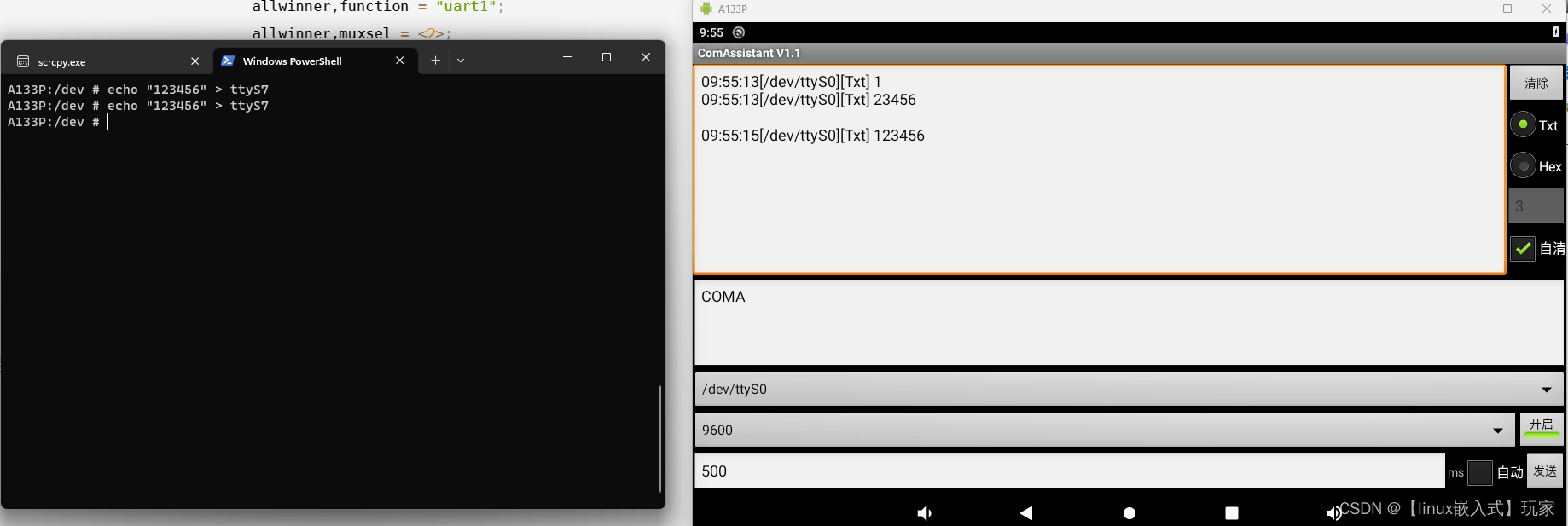
最后UART0就可以正常收到数据了。
总结:
虽然这个485调试花了很多时间,但是学会了很多调试技巧。
在全平台手动拉高拉低,物理手动拉低(镊子短接地)
对485了解更加深刻
对硬件原理图更加得心应手得找到想要的信息了
![[MAUI 项目实战] 手势控制音乐播放器: 手势交互](https://img-blog.csdnimg.cn/img_convert/f5848c99eeec45cac180e1c9f5c4c825.gif)


