光电编码器,是一种通过光电转换将输出轴上的机械几何位移量转换成脉冲或数字量的传感器。这是应用最多的传感器,光电编码器是由光源、光码盘和光敏元件组成。光栅盘是在一定直径的圆板上等分地开通若干个长方形孔。由于光电码盘与电动机同轴,电动机旋转时,光栅盘与电动机同速旋转,经发光二极管等电子元件组成的检测装置检测输出若干脉冲信号,通过计算每秒光电编码器输出脉冲的个数就能反映当前电动机的转速。此外,为判断旋转方向,码盘还可提供相位相差90º的两路脉冲信号。根据检测原理,编码器可分为光学式、磁式、感应式和电容式。根据其刻度方法及信号输出形式,可分为增量式、绝对式以及混合式三种。
增量式编码器是直接利用光电转换原理输出三组方波脉冲A、B和Z相;A、B两组脉冲相位差90º,从而可方便地判断出旋转方向,而Z相为每转一个脉冲,用于基准点定位。它的优点是原理构造简单,机械平均寿命可在几万小时以上,抗干扰能力强,可靠性高,适合于长距离传输。其缺点是无法输出轴转动的绝对位置信息。
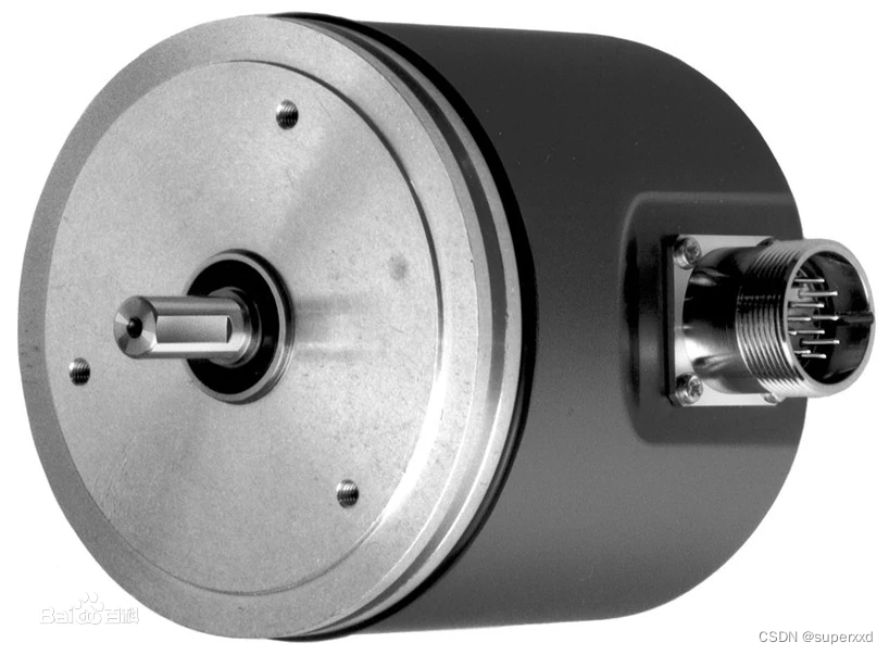
本应用采用增量式编码器进行速度和里程的精确测量,在软件设计上采用中断方式采集编码器输入的脉冲信号,本例的脉冲转一圈输出2000个脉冲。采用M/T测速原理,利用PIC32的定时器作为时间参照系,与采集的脉冲数一起进行比例运算,得出实时速度,并可以实现里程的累计预算。应用于实时测速和里程双测量的应用,大量应用于速度校正,里程计量,恒速控制等工业测量控制场景。
//************************************************************
//Copyright(C)2010
//					 编码器采样算法源文件
//文件名称:Encoder.c
//文件标识:(内参)
//摘    要:
//			1.配合头文件使用;
//			2.
//			3.
//
//当前版本:1.0
//作    者:xxd
//完成日期:2010.7.7
//
//取代版本:无
//原 作 者:无
//完成日期:无
//encoder  2000脉冲/每转
// |<------------M1--------------------------->|
// |----|    |----|    |----         |----|    |----|
// |    |    |    |    |    .........|    |    |    | 编码器脉冲
//_|    |____|    |____|             |    |____|    |
// |<-------------M2-------------------------->|
// ||||||||||||||||||||||||||||||||||||||||||||||||||||||||||
// |||||||||||||||||||||||||||||||||||||||||||||||||||||||||| f
// ||||||||||||||||||||||||||||||||||||||||||||||||||||||||||
// M/T测速原理图

//采用脉冲捕获技术实现改进的M/T法对增量式编码器进行速度和角度的实时采集
//M/T法测速是表示同时测量一定个数的编码器脉冲和产生这些脉冲所花的时间,在
//整个速度范围内都有较好的准确性,但对于低速,该法需要较长的检测时间才能
//保证结果的准确性,无法满足转速检测系统的快速动态响应指标,原因为采样周
//期确定为产生M1个编码器脉冲的时间,随着转速升高,编码器脉冲频率变大,采
//样周期变小,相对误差就增大了
//        60f     M1
//    N=------ * ----
//         P      M2
//P-------->光电编码器每转的脉冲数 本编码器为2000
//M1------->光电编码器脉冲计数值
//M2------->时钟脉冲计数值
//N-------->转速
//算法改进:
//根据速度情况实时改变M1的值,速度降低则减少M1的值,以改善低速段测速的动态响应性能
//算法软件上采用在高速段增加M1值使采样周期基本不变。因而其相对误差也基本不变,在低
//转速段M1值可降到1,满足系统的动态响应要求
//采用PIC32MX捕获模块和两个定时器实现对输入脉冲的上升沿或下降沿和时钟脉冲准确计数,
//采样周期为10ms
//RC2,接入脚为DIN5,增量编码器输出脉冲接入本脚
//编码器脉冲上升沿触发捕获模块,并将直接计数TIMER3中的数字计数值,在1毫秒的系统时钟中断中
//以每10次计算一次速度
//********************************************************************************

#define  ENCODER_GLOABLE
#include "encoder.h"
#include "Evc300Control.h"

/* Private variables ---------------------------------------------------------*/
static INT16S hPrevious_angle=0, hSpeed_Buffer[SPEED_BUFFER_SIZE], hRot_Speed=0;
static INT8U bSpeed_Buffer_Index = 0;
static volatile INT16U hEncoder_Timer_Overflow=0;
static BOOLEAN bIs_First_Measurement = TRUE;
static BOOLEAN bError_Speed_Measurement = FALSE;

/*******************************************************************************
* Function Name  : ENC_Init
* Description    : General Purpose Timer x set-up for encoder speed/position
*                  sensors
* Input          : None
* Output         : None
* Return         : None
*******************************************************************************/
void ENC_Init(void)
{

  //Clear interrupt flag
    mT3ClearIntFlag();
    ENC_Clear_Speed_Buffer();
    // Setup Timer 3
    OpenTimer3(T3_ON |T3_SOURCE_EXT | T3_PS_1_1, ENCODER_TIMER_TICK);

   // set up the timer interrupt with a priority of 2
    ConfigIntTimer3(T3_INT_ON | T3_INT_PRIOR_3 | T3_INT_SUB_PRIOR_1);

    mT3IntEnable(1);
/*
T3CON = 0x0; // Stop Timer and clear control register
T3CONSET = 0x0002; // Set prescaler at 1:256, external clock source
TMR3 = 0x0; // Clear timer register
PR3 = ENCODER_TIMER_TICK; // Load period register
T3CONSET = 0x8000; // Start Timer
mT3SetIntPriority(1);
mT3IntEnable(1);
*/
}
void ENC_Close()
{
   CloseTimer3();
}
/*******************************************************************************
* Function Name  : ENC_Get_Electrical_Angle
* Description    : Returns the absolute electrical Rotor angle
* Input          : None
* Output         : None
* Return         : Rotor electrical angle: 0 -> 0 degrees,
*                                          S16_MAX-> 180 degrees,
*                                          S16_MIN-> -180 degrees
*                  Mechanical angle can be derived calling this function and
*                  dividing by POLE_PAIR_NUM
*******************************************************************************/
INT16S ENC_Get_Electrical_Angle(void)
{
  INT32S temp;

  temp = (INT32S)(ReadTimer3()) * (INT32S)(U32_MAX / (ENCODER_PPR));
  temp *= POLE_PAIR_NUM;
  return((INT16S)(temp/65536)); // INT16S result
}

/*******************************************************************************
* Function Name  : ENC_Get_Mechanical_Angle
* Description    : Returns the absolute mechanical Rotor angle
* Input          : None
* Output         : None
* Return         : Rotor mechanical angle: 0 -> 0 degrees, S16_MAX-> 180 degrees,
                                            S16_MIN-> -180 degrees
*******************************************************************************/
INT16S ENC_Get_Mechanical_Angle(void)
{
  INT32S temp;

  temp = (INT32S)(ReadTimer3()) * (INT32S)(U32_MAX / (ENCODER_PPR)) ;
  return((INT16S)(temp/65536)); // INT16S result
}

/*******************************************************************************
* Function Name  : ENC_ResetEncoder
* Description    : Write the encoder counter with the value corresponding to
*                  ALIGNMENT_ANGLE
* Input          : None
* Output         : None
* Return         : None
*******************************************************************************/
void ENC_ResetEncoder(void)
{
  //Reset counter
  WriteTimer3(COUNTER_RESET);
}


/*******************************************************************************
* Function Name  : ENC_Clear_Speed_Buffer
* Description    : Clear speed buffer used for average speed calculation
* Input          : None
* Output         : None
* Return         : None
*******************************************************************************/
void ENC_Clear_Speed_Buffer(void)
{
  INT32U i;

  for (i=0;i<SPEED_BUFFER_SIZE;i++)
  {
    hSpeed_Buffer[i] = 0;
  }
  bIs_First_Measurement = TRUE;
}

/*******************************************************************************
* Function Name  : ENC_Calc_Rot_Speed
* Description    : Compute return latest speed measurement
* Input          : None
* Output         : INT16S
* Return         : Return motor speed in 0.1 Hz resolution. Since the encoder is
                   used as speed sensor, this routine will return the mechanical
                   speed of the motor (NOT the electrical frequency)
                   Mechanical frequency is equal to electrical frequency/(number
                   of pair poles).
*******************************************************************************/
INT16S ENC_Calc_Rot_Speed(void)
{
  INT32S wDelta_angle;
  INT16U hEnc_Timer_Overflow_sample_one, hEnc_Timer_Overflow_sample_two;
  INT16U hCurrent_angle_sample_one, hCurrent_angle_sample_two;
  signed long long temp;
  INT16S haux;

  if (!bIs_First_Measurement)
  {
    // 1st reading of overflow counter
    hEnc_Timer_Overflow_sample_one = hEncoder_Timer_Overflow;
    // 1st reading of encoder timer counter
    hCurrent_angle_sample_one = ReadTimer3();
    // 2nd reading of overflow counter
    hEnc_Timer_Overflow_sample_two = hEncoder_Timer_Overflow;
    // 2nd reading of encoder timer counter
    hCurrent_angle_sample_two = ReadTimer3();

    // Reset hEncoder_Timer_Overflow and read the counter value for the next
    // measurement
    hEncoder_Timer_Overflow = 0;
    haux = ReadTimer3();

    if (hEncoder_Timer_Overflow != 0)
    {
      haux = ReadTimer3();
      hEncoder_Timer_Overflow = 0;
    }

    if (hEnc_Timer_Overflow_sample_one != hEnc_Timer_Overflow_sample_two)
    { //Compare sample 1 & 2 and check if an overflow has been generated right
      //after the reading of encoder timer. If yes, copy sample 2 result in
      //sample 1 for next process
      hCurrent_angle_sample_one = hCurrent_angle_sample_two;
      hEnc_Timer_Overflow_sample_one = hEnc_Timer_Overflow_sample_two;
    }
 /*
    if ( (ENCODER_TIMER->CR1 & TIM_CounterMode_Down) == TIM_CounterMode_Down)
    {// encoder timer down-counting
      wDelta_angle = (INT32S)(hCurrent_angle_sample_one - hPrevious_angle -
                    (hEnc_Timer_Overflow_sample_one) * (4*ENCODER_PPR));
    }
    else
*/
    {//encoder timer up-counting
      wDelta_angle = (INT32S)(hCurrent_angle_sample_one - hPrevious_angle +
                    (hEnc_Timer_Overflow_sample_one) * (4*ENCODER_PPR));
    }

    // speed computation as delta angle * 1/(speed sempling time)
    temp = (signed long long)(wDelta_angle * SPEED_SAMPLING_FREQ);
    temp *= SPEED_RESOLVING;  //  resolution
    temp /= (ENCODER_PPR);

  } //is first measurement, discard it
  else
  {
    bIs_First_Measurement = FALSE;
    temp = 0;
    hEncoder_Timer_Overflow = 0;
    haux = ReadTimer3();
    // Check if hEncoder_Timer_Overflow is still zero. In case an overflow IT
    // occured it resets overflow counter and wPWM_Counter_Angular_Velocity
    if (hEncoder_Timer_Overflow != 0)
    {
      haux = ReadTimer3();
      hEncoder_Timer_Overflow = 0;
    }
  }

  hPrevious_angle = haux;

  return((INT16S) temp);
}

/*******************************************************************************
* Function Name  : ENC_Get_Mechanical_Speed
* Description    : Export the value of the smoothed motor speed computed in
*                  ENC_Calc_Average_Speed function
* Input          : None
* Output         : INT16S
* Return         : Return motor speed in 0.1 Hz resolution. This routine
                   will return the average mechanical speed of the motor.
*******************************************************************************/

INT16S ENC_Get_Mechanical_Speed(void)
{
  return(hRot_Speed);
}
#define PI 3.14159
#define S_PERHOUR   3600 //每小时的秒数
//nRollerDiameter直径单位毫米
float ENC_Get_Line_Speed(int nRollerDiameter)
{
   float fSpeed=0;
   fSpeed=((PI*nRollerDiameter*hRot_Speed*S_PERHOUR)/SPEED_RESOLVING)/1000/1000;//线速度公里每小时
  return(hRot_Speed);
}

/*******************************************************************************
* Function Name  : ENC_Calc_Average_Speed
* Description    : Compute smoothed motor speed based on last SPEED_BUFFER_SIZE
                   informations and store it variable
* Input          : None
* Output         : INT16S
* Return         : Return rotor speed in 0.1 Hz resolution. This routine
                   will return the average mechanical speed of the motor.
*******************************************************************************/
void ENC_Calc_Average_Speed(void)
{
  INT32S wtemp;
  INT16U hAbstemp;
  INT32U i;
  INT8U static bError_counter;

  wtemp = ENC_Calc_Rot_Speed();
  hAbstemp = ( wtemp < 0 ? - wtemp :  wtemp);

/* Checks for speed measurement errors when in RUN State and saturates if
                                                                    necessary*/
  if (EVC300_State  == RUN)
  {
    if(hAbstemp <=MINIMUM_MECHANICAL_SPEED)
    {
      if (wtemp < 0)
      {
        wtemp = -(INT32S)(MINIMUM_MECHANICAL_SPEED);
      }
      else
      {
        wtemp = MINIMUM_MECHANICAL_SPEED;
      }
      bError_counter++;
    }
    else  if (hAbstemp > MAXIMUM_MECHANICAL_SPEED)
          {
            if (wtemp < 0)
            {
              wtemp = -(INT32S)(MAXIMUM_MECHANICAL_SPEED);
            }
            else
            {
              wtemp = MAXIMUM_MECHANICAL_SPEED;
            }
            bError_counter++;
          }
          else
          {
            bError_counter = 0;
          }

    if (bError_counter >= MAXIMUM_ERROR_NUMBER)
    {
     bError_Speed_Measurement = TRUE;
    }
    else
    {
     bError_Speed_Measurement = FALSE;
    }
  }//end if(state==RUN)
  else
  {
    bError_Speed_Measurement = FALSE;
    bError_counter = 0;
  }

/* Compute the average of the read speeds */

  hSpeed_Buffer[bSpeed_Buffer_Index] = (INT16S)wtemp;
  bSpeed_Buffer_Index++;

  if (bSpeed_Buffer_Index == SPEED_BUFFER_SIZE)
  {
    bSpeed_Buffer_Index = 0;
  }

  wtemp=0;

  for (i=0;i<SPEED_BUFFER_SIZE;i++)
    {
    wtemp += hSpeed_Buffer[i];
    }
  wtemp /= SPEED_BUFFER_SIZE;

  hRot_Speed = ((INT16S)(wtemp));
}

/*******************************************************************************
* Function Name  : ENC_ErrorOnFeedback
* Description    : Check for possible errors on speed measurement when State is
*                  RUN. After MAXIMUM_ERROR_NUMBER consecutive speed measurement
*                  errors, the function return TRUE, else FALSE.
*                  Function return
* Input          : None
* Output         : INT16S
* Return         : boolean variable
*******************************************************************************/
BOOLEAN ENC_ErrorOnFeedback(void)
{
 return(bError_Speed_Measurement);
}

/*******************************************************************************
* Function Name : ENC_Start_Up
* Description   : The purpose of this function is to perform the alignment of
*
* Input : details the input parameters.
* Output : details the output parameters.
* Return : details the return value.
*******************************************************************************/
void ENC_Start_Up(void)
{
    EVC300_State = RUN;
}

/*******************************************************************************
* Function Name  : TIMx_IRQHandler
* Description    : This function handles TIMx Update interrupt request.
                   Encoder unit connected to TIMx (x = 2,3 or 4)
* Input          : None
* Output         : None
* Return         : None
*******************************************************************************/
#ifdef USE_IRQ_MAC
void __attribute__( (interrupt(ipl1), vector(12))) BSP_TIM3ISR( void );
#endif
  void TIM3_IRQHandler(void)
  {
    mT3ClearIntFlag();
    if (hEncoder_Timer_Overflow != U16_MAX)
    {
     hEncoder_Timer_Overflow++;
    }

  }


/******************* (C) COPYRIGHT 2008  *****END OF FILE****/
