STM32模拟I2C协议获取HMC5883L电子罗盘磁角度数据(HAL)
HMC5883L 传感器采用霍尼韦尔各向异性磁阻(AMR)技术,应用于罗盘和三轴磁场角度检测领域,常用于水平物体转动的角度识别。HMC5883L 采用I2C总线接口,2.16~3.6V供电范围,带有校准测试功能。
HMC5883L的硬件连接
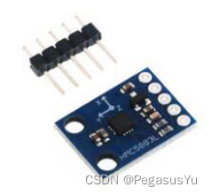
HMC5883L的硬件连接有5个管脚,除了VCC和GND,以及I2C的SCK和SDA,还有一根INT中断线,用于向MCU报告数据可读取。
HMC5883L的寄存器说明
HMC5883L有如下的一些寄存器,按作用分为4种:
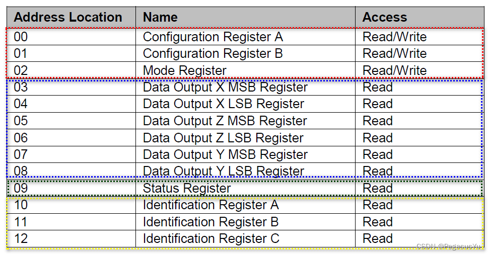
地址00~02用于配置测试过程中的采样平均次数,数据输出率,测量配置(对应正常或自检测试),增益配置,测量模式(正常或自检测试)。
地址03~08存放测试结果数据,每轴16位,用两个字节存放,注意这6个地址对应的顺序是 X轴–Z轴–Y轴,而不是 X轴–Y轴–Z轴。
地址09是状态的读寄存器,可以通过读取状态获得结果数据是否可读取,替代的方式使用HMC5883L输出的上升沿硬件中断线。
地址10~12存放一些识别码,一般用于读出比较,验证I2C总线访问是否成功。
STM32工程基本配置
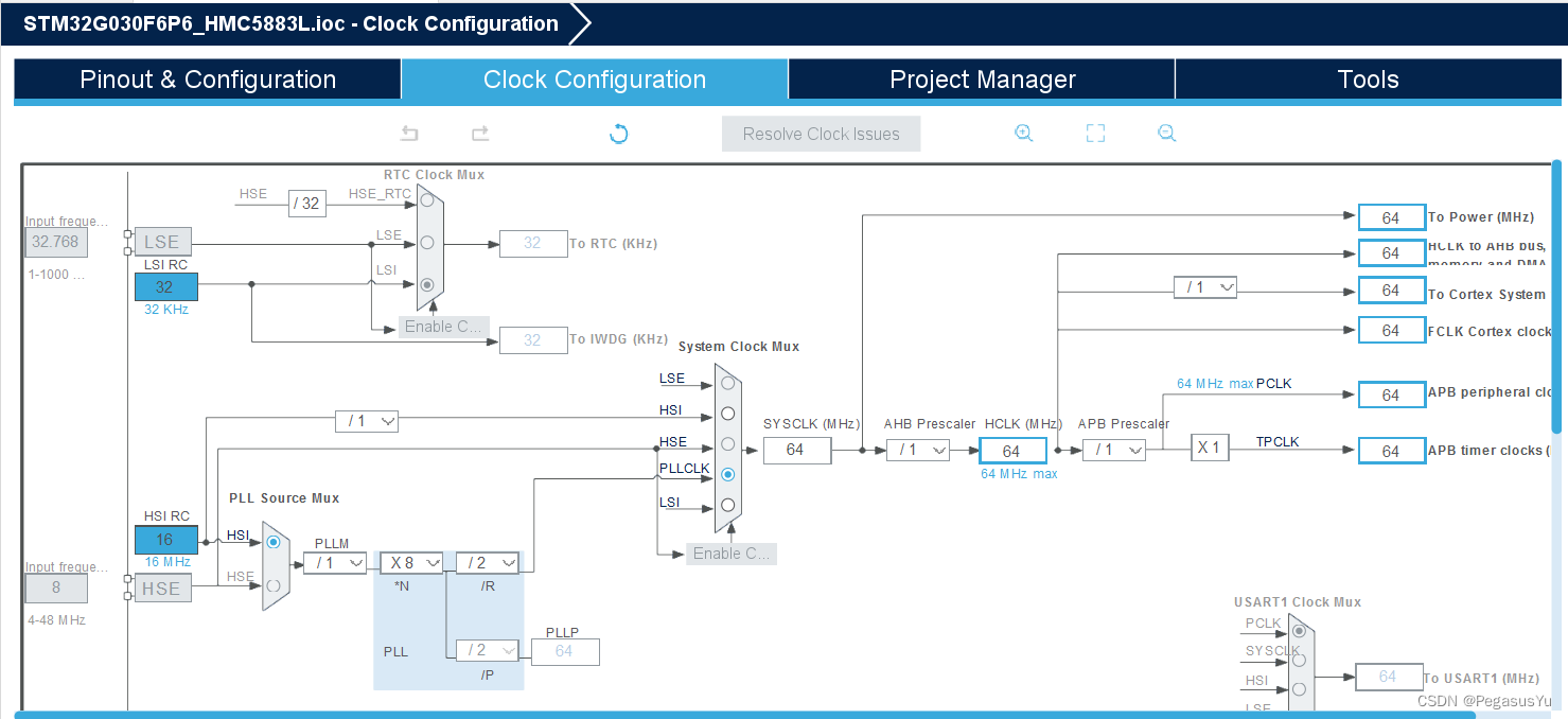
这里以STM32G030F6P6以及STM32CUBEIDE开发平台为例,通过模拟I2C访问HMC5883L的方式,实现地磁角度的识别,实现的功能有:
- 写读HMC5883L内部寄存器
- 配置HMC5883L为正常工作模式,并获取地磁角度数据
- 配置HMC5883L为自检工作模式,实现自检校准系数的应用
- 实现HMC5883L的温度校准系数的生成和应用
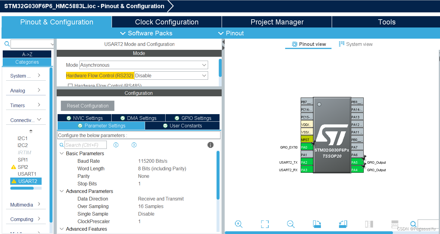
首先建立基本工程并配置时钟:
配置UART2串口用于打印输出:
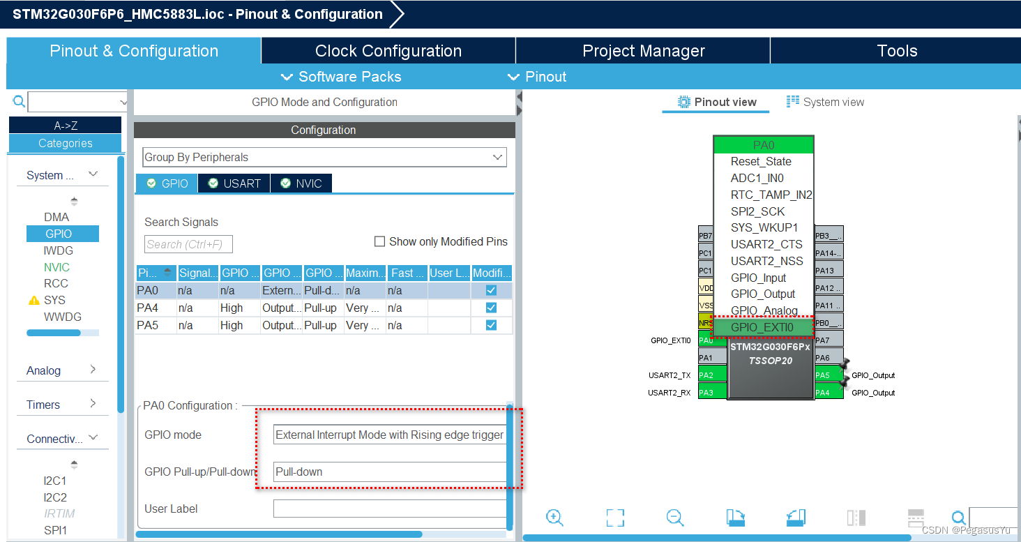
任选三个GPIO用于接口HMC5883L,这里用:
PA0: INT
PA4: SCK
PA5: SDA
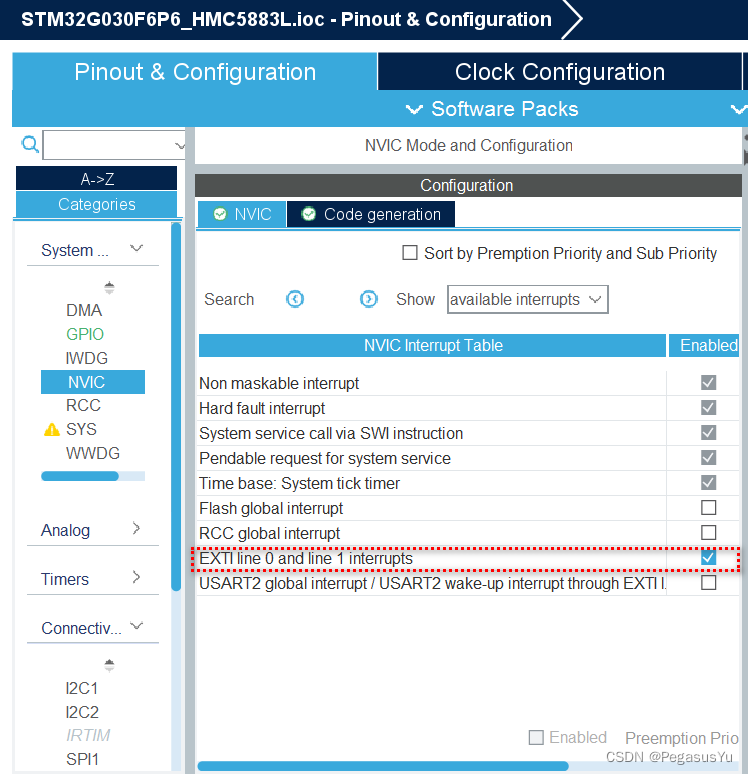
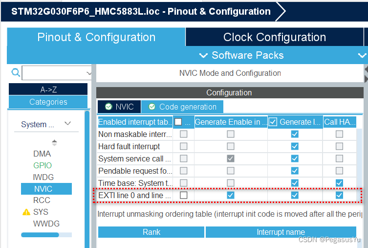
PA0配置为上升沿触发中断管脚并使能中断:
I2C配置为Open-drain模式:
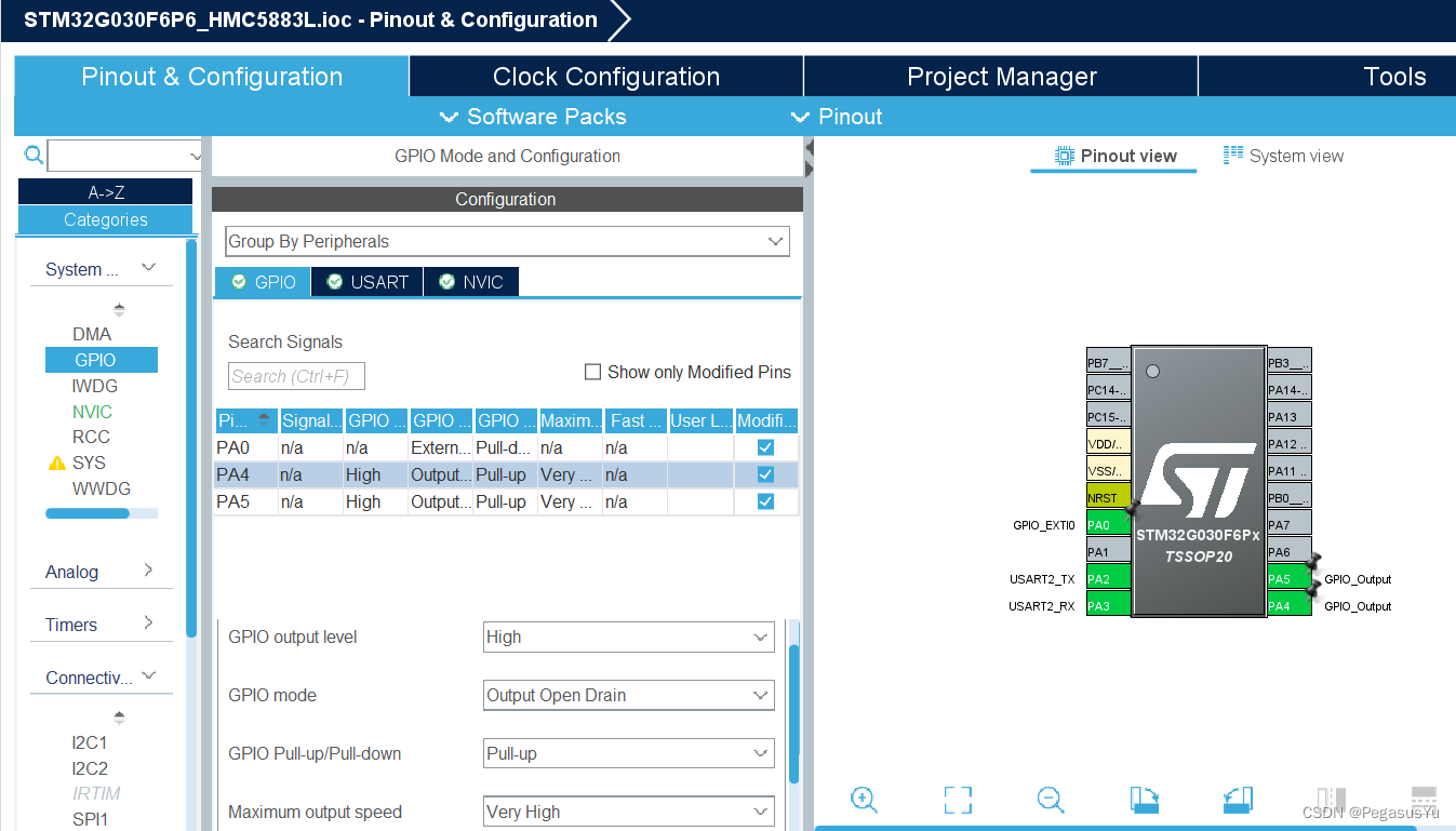
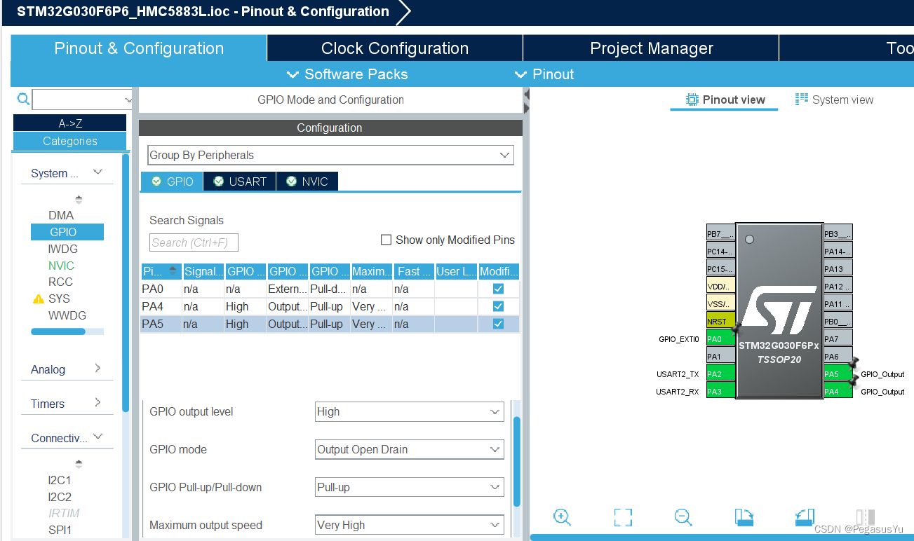
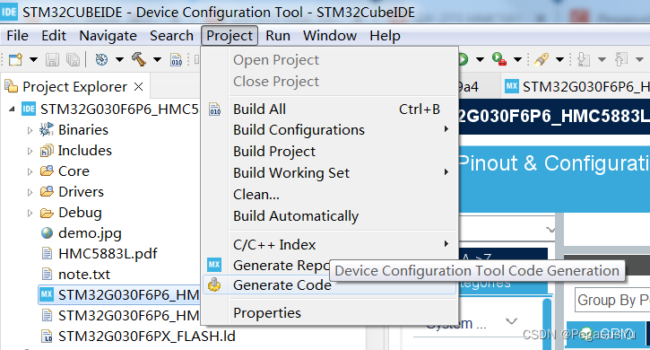
保存并生成初始工程代码:
注意如果代码编译后空间不够,参考 STM32 region `FLASH‘ overflowed by xxx bytes 问题解决
STM32工程组件代码
-
工程里会使用printf打印输出,相关的代码部分说明参考 STM32 UART串口printf函数应用及浮点打印代码空间节省 (HAL)
-
模拟I2C的实现部分要用到微秒级延时函数,相关的代码部分说明参考 STM32 HAL us delay(微秒延时)的指令延时实现方式及优化
I2C基本访问的代码如下:
void I2C_Init(void)
{

	SCL_OUT_H;
	SDA_OUT_H;
	PY_Delay_us_t(2000000); //Provide device stability time

}

void I2C_Start(void)
{
	PY_Delay_us_t(us_num) ;
	SDA_OUT_H;
	SCL_OUT_H;
	PY_Delay_us_t(us_num/2) ;
	SDA_OUT_L;
	PY_Delay_us_t(us_num/2) ;
	SCL_OUT_L;
}

void I2C_Stop(void)
{
	SCL_OUT_L;
	PY_Delay_us_t(us_num) ;
	SDA_OUT_L;
	PY_Delay_us_t(us_num) ;
	SCL_OUT_H;
	PY_Delay_us_t(us_num) ;
	SDA_OUT_H;
	PY_Delay_us_t(us_num) ;
}

void I2C_Write_Ack(void)
{

    PY_Delay_us_t(us_num/2) ;
	SDA_OUT_L;
	PY_Delay_us_t(us_num/2) ;
	SCL_OUT_H;
	PY_Delay_us_t(us_num) ;
	SCL_OUT_L;
	SDA_OUT_H;

}

uint8_t I2C_Read_Ack(void)
{
	uint8_t status=0;

	SCL_OUT_L;
	PY_Delay_us_t(us_num/2) ;
	SDA_OUT_H;
	PY_Delay_us_t(us_num/2) ;
	status = SDA_IN;
	SCL_OUT_H;
	PY_Delay_us_t(us_num) ;
	SCL_OUT_L;
	SDA_OUT_L;

	return status;

}


void I2C_Send_Byte(uint8_t txd){


    for(uint8_t i=0;i<8;i++)
    {
    	PY_Delay_us_t(us_num/2) ;
        if((txd&0x80)>>7) SDA_OUT_H;
        else SDA_OUT_L;
        txd<<=1;
        PY_Delay_us_t(us_num/2) ;
        SCL_OUT_H;
        PY_Delay_us_t(us_num) ;
		SCL_OUT_L;
    }

    SDA_OUT_L;
}

uint8_t I2C_Read_Byte(unsigned char rdack)
{
	uint8_t rxd=0;


    for(uint8_t i=0;i<8;i++ )
	{
    	SCL_OUT_L;
    	PY_Delay_us_t(us_num/2) ;
    	SDA_OUT_H;
    	PY_Delay_us_t(us_num/2) ;
    	SCL_OUT_H;
        rxd<<=1;
        if(SDA_IN) rxd++;
        PY_Delay_us_t(us_num) ;
    }

    SCL_OUT_L;
    SDA_OUT_H;

    if (rdack) I2C_Write_Ack();

    return rxd;
}
3. HMC5883L的访问操作代码:
#define CRA 0x00
#define CRB 0x01
#define MR 0x02
#define DOXMR 0x03
#define DOXLR 0x04
#define DOZMR 0x05
#define DOZLR 0x06
#define DOYMR 0x07
#define DOYLR 0x08
#define SR 0x09
#define IRA 0x0A
#define IRB 0x0B
#define IRC 0x0C
#define SelfTest_EN 1
uint8_t SF=0; //Self Test Flag
void PY_HMC5883L_WriteReg(uint8_t WrAddr, uint8_t data)
{
uint8_t daddr;
daddr = 0x3c; //HMC5883L device address (0x1E<<1)
I2C_Start();
I2C_Send_Byte(daddr);
I2C_Read_Ack();
I2C_Send_Byte(WrAddr);
I2C_Read_Ack();
I2C_Send_Byte(data);
I2C_Read_Ack();
I2C_Stop();
}
uint8_t PY_HMC5883L_ReadReg(uint8_t RdAddr)
{
uint8_t RegValue = 0;
uint8_t daddr;
daddr = 0x3c; //HMC5883L device address (0x1E<<1)
I2C_Start();
I2C_Send_Byte(daddr);
I2C_Read_Ack();
I2C_Send_Byte(RdAddr);
I2C_Read_Ack();
I2C_Start();
I2C_Send_Byte(daddr+1);
I2C_Read_Ack();
RegValue=I2C_Read_Byte(0);
I2C_Stop();
return RegValue;
}
/*Note:
To minimize the communication between the master and this device, the address pointer updated automatically without master intervention.
This automatic address pointer update has two additional features. First when address 12 or higher is accessed the pointer updates to address 00 and secondly when address 08 is reached, the pointer rolls back to address 03. Logically, the address pointer operation functions as shown below.
If (address pointer = 08) then address pointer = 03
Else if (address pointer >= 12) then address pointer = 0
Else (address pointer) = (address pointer) + 1
*/
int XD, YD, ZD;
uint16_t Angle;
double XFactor = 1.0, YFactor = 1.0, ZFactor = 1.0; //Correction factor coming for self test process
double XFactor_T = 1.0, YFactor_T = 1.0, ZFactor_T = 1.0; //Correction factor coming for self test process for temperature impact
void PY_HMC5883L_ReadData(void)
{
uint8_t data[6];
uint16_t x, y, z;
double angle;
uint8_t daddr;
daddr = 0x3c; //HMC5883L device address (0x1E<<1)
I2C_Start();
I2C_Send_Byte(daddr);
I2C_Read_Ack();
I2C_Send_Byte(0x03);
I2C_Read_Ack();
I2C_Start();
I2C_Send_Byte(daddr+1);
I2C_Read_Ack();
data[0]=I2C_Read_Byte(1);
data[1]=I2C_Read_Byte(1);
data[2]=I2C_Read_Byte(1);
data[3]=I2C_Read_Byte(1);
data[4]=I2C_Read_Byte(1);
data[5]=I2C_Read_Byte(0);
I2C_Stop();
x = (((uint16_t)data[0])<<8)|((uint16_t)data[1]);
z = (((uint16_t)data[2])<<8)|((uint16_t)data[3]);
y = (((uint16_t)data[4])<<8)|((uint16_t)data[5]);
if((x>>15)!=0) XD = -(0x10000-x);
else XD = x;
if((y>>15)!=0) YD = -(0x10000-y);
else YD = y;
if((z>>15)!=0) ZD = -(0x10000-z);
else ZD = z;
angle = atan2((double)YD*YFactor*YFactor_T,(double)XD*XFactor*XFactor_T);
if(angle<0) angle += 6.28318530718 ; //Converted to range: 0 ~ 2π
Angle = angle*(360/6.2831853071); //Converted to °
}
/*
SELF TEST OPERATION
To check the HMC5883L for proper operation, a self test feature in incorporated in which the sensor offset straps are excited to create a nominal field strength (bias field) to be measured. To implement this self test, the least significant bits (MS1 and MS0) of configuration register A are changed from 00 to 01.
Then, by placing the mode register into single-measurement mode (0x01), two data acquisition cycles will be made on each magnetic vector. The first acquisition will be a set pulse followed shortly by measurement data of the external field. The second acquisition will have the offset strap excited (about 10 mA) in the positive bias mode for X, Y, and Z axes to create about a ±1.1 gauss self test field plus the external field. The first acquisition values will be subtracted from the second acquisition, and the net measurement will be placed into the data output registers.
If the configuration register B is left at the factory default value of 0x40, values around +951 ADC LSB (1.16 Ga * 820 LSB/Ga) will be placed in the X and Y data output registers and around +886 (1.08 Ga * 1820 LSB/Ga) in Z data output register. To leave the self test mode, change MS1 and MS0 bit of the configuration register A back to 00. Also change the mode register if single-measurement mode is not the intended mode of operation.
*/
void PY_HMC5883L_SELF_TEST(void)
{
SF=1;
XFactor = 1.0; YFactor = 1.0; ZFactor = 1.0;
PY_HMC5883L_WriteReg(CRA, 0X71);//samples average: 8; data output rate: 15Hz; measure mode: self test of positive bias
PY_HMC5883L_WriteReg(CRB, 0X20);//gain: ± 1.3 Ga
PY_HMC5883L_WriteReg(MR, 0X01); //Single-Measurement Mode
HAL_NVIC_ClearPendingIRQ(EXTI0_1_IRQn);
}
/*
Alternatively, the built-in self test can be used to periodically compensate the scaling errors due to temperature variations.
A compensation factor can be found by comparing the self test outputs with the ones obtained at a known temperature.
For example, if the self test output is 1130 at room temperature and 1150 at the current temperature then a scale factor of
(1130/1150) should be applied to all current magnetic readings. A temperature sensor is not required using this method.
*/
int XD_T0, YD_T0, ZD_T0;
int XD_T1, YD_T1, ZD_T1;
void PY_HMC5883L_T0Param(void)
{
SF=2;
XFactor_T = 1.0; YFactor_T = 1.0; ZFactor_T = 1.0;
PY_HMC5883L_WriteReg(CRA, 0X71);//samples average: 8; data output rate: 15Hz; measure mode: self test of positive bias
PY_HMC5883L_WriteReg(CRB, 0X20);//gain: ± 1.3 Ga
PY_HMC5883L_WriteReg(MR, 0X01); //Single-Measurement Mode
HAL_NVIC_ClearPendingIRQ(EXTI0_1_IRQn);
while(SF!=0) PY_Delay_us_t(1000);
PY_HMC5883L_WriteReg(CRA, 0X70);//samples average: 8; data output rate: 15Hz; measure mode: normal
PY_HMC5883L_WriteReg(CRB, 0X20);//gain: ± 1.3 Ga
PY_HMC5883L_WriteReg(MR, 0X00);//continuous-measurement mode
HAL_NVIC_ClearPendingIRQ(EXTI0_1_IRQn);
}
void PY_HMC5883L_T1Param(void)
{
SF=3;
XFactor_T = 1.0; YFactor_T = 1.0; ZFactor_T = 1.0;
PY_HMC5883L_WriteReg(CRA, 0X71);//samples average: 8; data output rate: 15Hz; measure mode: self test of positive bias
PY_HMC5883L_WriteReg(CRB, 0X20);//gain: ± 1.3 Ga
PY_HMC5883L_WriteReg(MR, 0X01); //Single-Measurement Mode
HAL_NVIC_ClearPendingIRQ(EXTI0_1_IRQn);
while(SF!=0) PY_Delay_us_t(1000);
PY_HMC5883L_WriteReg(CRA, 0X70);//samples average: 8; data output rate: 15Hz; measure mode: normal
PY_HMC5883L_WriteReg(CRB, 0X20);//gain: ± 1.3 Ga
PY_HMC5883L_WriteReg(MR, 0X00);//continuous-measurement mode
HAL_NVIC_ClearPendingIRQ(EXTI0_1_IRQn);
}
void PY_HMC5883L_Init(void)
{
uint8_t Reg[13];
Reg[0] = PY_HMC5883L_ReadReg(CRA);
Reg[1] = PY_HMC5883L_ReadReg(CRB);
Reg[2] = PY_HMC5883L_ReadReg(MR);
Reg[3] = PY_HMC5883L_ReadReg(DOXMR);
Reg[4] = PY_HMC5883L_ReadReg(DOXLR);
Reg[5] = PY_HMC5883L_ReadReg(DOZMR);
Reg[6] = PY_HMC5883L_ReadReg(DOZLR);
Reg[7] = PY_HMC5883L_ReadReg(DOYMR);
Reg[8] = PY_HMC5883L_ReadReg(DOYLR);
Reg[9] = PY_HMC5883L_ReadReg(SR);
Reg[10] = PY_HMC5883L_ReadReg(IRA); //data = 0x48
Reg[11] = PY_HMC5883L_ReadReg(IRB); //data = 0x34
Reg[12] = PY_HMC5883L_ReadReg(IRC); //data = 0x33
if(!((Reg[10]==0x48)&&(Reg[11]==0x34)&&(Reg[12]==0x33)))
{
printf("HMC5883 I2C access failure!\r\n");
printf("HMC5883 regs: 0x%x 0x%x 0x%x 0x%x 0x%x 0x%x 0x%x 0x%x 0x%x 0x%x 0x%x 0x%x 0x%x\r\n", Reg[0], Reg[1], Reg[2], Reg[3], Reg[4], Reg[5], Reg[6], Reg[7], Reg[8], Reg[9], Reg[10], Reg[11], Reg[12]);
return PY_HMC5883L_Init();
}
else
{
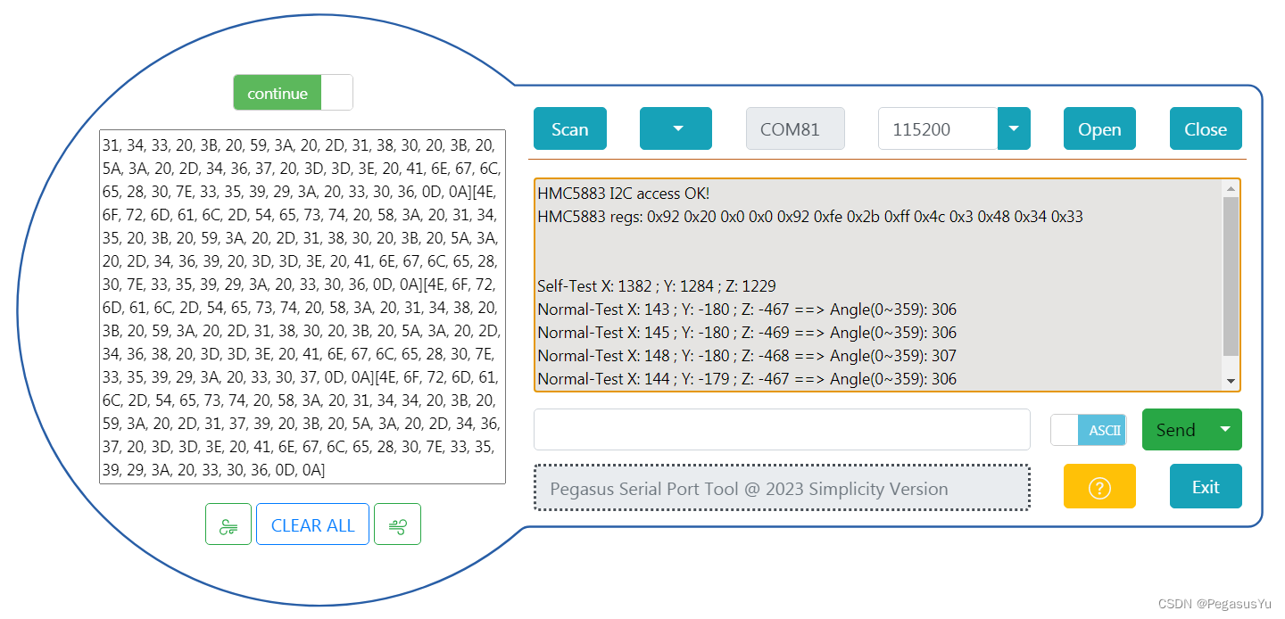
printf("HMC5883 I2C access OK!\r\n");
printf("HMC5883 regs: 0x%x 0x%x 0x%x 0x%x 0x%x 0x%x 0x%x 0x%x 0x%x 0x%x 0x%x 0x%x 0x%x\r\n", Reg[0], Reg[1], Reg[2], Reg[3], Reg[4], Reg[5], Reg[6], Reg[7], Reg[8], Reg[9], Reg[10], Reg[11], Reg[12]);
if(SelfTest_EN)
{
PY_HMC5883L_SELF_TEST();
while(SF!=0) PY_Delay_us_t(1000);
}
PY_HMC5883L_WriteReg(CRA, 0X70);//samples average: 8; data output rate: 15Hz; measure mode: normal
PY_HMC5883L_WriteReg(CRB, 0X20);//gain: ± 1.3 Ga
PY_HMC5883L_WriteReg(MR, 0X00);//continuous-measurement mode
HAL_NVIC_ClearPendingIRQ(EXTI0_1_IRQn);
}
}
而在GPIO的中断函数里做读取和处理:
void HAL_GPIO_EXTI_Rising_Callback(uint16_t GPIO_Pin)
{
	const float cr = 1.1*1090;  //1.1Gauss * 1090LSB/Gauss

	if (GPIO_Pin==GPIO_PIN_0)
	{
		PY_HMC5883L_ReadData();
		HAL_NVIC_ClearPendingIRQ(EXTI0_1_IRQn);

		if(SF==1)
		{
			printf("\r\n\r\nSelf-Test X: %d ; Y: %d ; Z: %d\r\n\r\n", XD, YD, ZD);
            XFactor = cr/XD;
            YFactor = cr/YD;
            ZFactor = cr/ZD;

			SF = 0;
		}
		else if(SF==2)
		{
            XD_T0 = XD;
            YD_T0 = YD;
            ZD_T0 = ZD;
            printf("\r\n\r\nT0 parameter test and set done!\r\n\r\n", XD, YD, ZD);

            SF = 0;
		}
		else if(SF==3)
		{
            XD_T1 = XD;
            YD_T1 = YD;
            ZD_T1 = ZD;
            printf("\r\n\r\nT1 parameter test and set done!\r\n\r\n", XD, YD, ZD);

            XFactor_T = XD_T0/XD_T1;
            YFactor_T = YD_T0/YD_T1;
            ZFactor_T = ZD_T0/ZD_T1;

            SF = 0;
		}
		else
		{
			printf("Normal-Test X: %d ; Y: %d ; Z: %d ==> Angle(0~359): %d\r\n", XD, YD, ZD, Angle);
		}

	}
}
STM32工程完整代码
完整的工程代码如下:
/* USER CODE BEGIN Header */
/**
  ******************************************************************************
  * @file           : main.c
  * @brief          : Main program body
  ******************************************************************************
  * @attention
  *
  * Copyright (c) 2022 STMicroelectronics.
  * All rights reserved.
  *
  * This software is licensed under terms that can be found in the LICENSE file
  * in the root directory of this software component.
  * If no LICENSE file comes with this software, it is provided AS-IS.
  *
  ******************************************************************************
  */
/*Written by Pegasus Yu in 2022*/
/* USER CODE END Header */
/* Includes ------------------------------------------------------------------*/
#include "main.h"

/* Private includes ----------------------------------------------------------*/
/* USER CODE BEGIN Includes */
#include <math.h>
#include "usart.h"
/* USER CODE END Includes */

/* Private typedef -----------------------------------------------------------*/
/* USER CODE BEGIN PTD */
__IO float usDelayBase;
void PY_usDelayTest(void)
{
  __IO uint32_t firstms, secondms;
  __IO uint32_t counter = 0;

  firstms = HAL_GetTick()+1;
  secondms = firstms+1;

  while(uwTick!=firstms) ;

  while(uwTick!=secondms) counter++;

  usDelayBase = ((float)counter)/1000;
}

void PY_Delay_us_t(uint32_t Delay)
{
  __IO uint32_t delayReg;
  __IO uint32_t usNum = (uint32_t)(Delay*usDelayBase);

  delayReg = 0;
  while(delayReg!=usNum) delayReg++;
}

void PY_usDelayOptimize(void)
{
  __IO uint32_t firstms, secondms;
  __IO float coe = 1.0;

  firstms = HAL_GetTick();
  PY_Delay_us_t(1000000) ;
  secondms = HAL_GetTick();

  coe = ((float)1000)/(secondms-firstms);
  usDelayBase = coe*usDelayBase;
}


void PY_Delay_us(uint32_t Delay)
{
  __IO uint32_t delayReg;

  __IO uint32_t msNum = Delay/1000;
  __IO uint32_t usNum = (uint32_t)((Delay%1000)*usDelayBase);

  if(msNum>0) HAL_Delay(msNum);

  delayReg = 0;
  while(delayReg!=usNum) delayReg++;
}
/* USER CODE END PTD */

/* Private define ------------------------------------------------------------*/
/* USER CODE BEGIN PD */
#define us_num 10

#define SCL_OUT_H HAL_GPIO_WritePin(GPIOA, GPIO_PIN_4, GPIO_PIN_SET)
#define SCL_OUT_L HAL_GPIO_WritePin(GPIOA, GPIO_PIN_4, GPIO_PIN_RESET)
#define SDA_OUT_H HAL_GPIO_WritePin(GPIOA, GPIO_PIN_5, GPIO_PIN_SET)
#define SDA_OUT_L HAL_GPIO_WritePin(GPIOA, GPIO_PIN_5, GPIO_PIN_RESET)
#define SDA_IN HAL_GPIO_ReadPin(GPIOA, GPIO_PIN_5)

#define INT_IN HAL_GPIO_ReadPin(GPIOA, GPIO_PIN_6)

void I2C_Init(void)
{

	SCL_OUT_H;
	SDA_OUT_H;
	PY_Delay_us_t(2000000); //Provide device stability time

}

void I2C_Start(void)
{
	PY_Delay_us_t(us_num) ;
	SDA_OUT_H;
	SCL_OUT_H;
	PY_Delay_us_t(us_num/2) ;
	SDA_OUT_L;
	PY_Delay_us_t(us_num/2) ;
	SCL_OUT_L;
}

void I2C_Stop(void)
{
	SCL_OUT_L;
	PY_Delay_us_t(us_num) ;
	SDA_OUT_L;
	PY_Delay_us_t(us_num) ;
	SCL_OUT_H;
	PY_Delay_us_t(us_num) ;
	SDA_OUT_H;
	PY_Delay_us_t(us_num) ;
}

void I2C_Write_Ack(void)
{

    PY_Delay_us_t(us_num/2) ;
	SDA_OUT_L;
	PY_Delay_us_t(us_num/2) ;
	SCL_OUT_H;
	PY_Delay_us_t(us_num) ;
	SCL_OUT_L;
	SDA_OUT_H;

}

uint8_t I2C_Read_Ack(void)
{
	uint8_t status=0;

	SCL_OUT_L;
	PY_Delay_us_t(us_num/2) ;
	SDA_OUT_H;
	PY_Delay_us_t(us_num/2) ;
	status = SDA_IN;
	SCL_OUT_H;
	PY_Delay_us_t(us_num) ;
	SCL_OUT_L;
	SDA_OUT_L;

	return status;

}


void I2C_Send_Byte(uint8_t txd){


    for(uint8_t i=0;i<8;i++)
    {
    	PY_Delay_us_t(us_num/2) ;
        if((txd&0x80)>>7) SDA_OUT_H;
        else SDA_OUT_L;
        txd<<=1;
        PY_Delay_us_t(us_num/2) ;
        SCL_OUT_H;
        PY_Delay_us_t(us_num) ;
		SCL_OUT_L;
    }

    SDA_OUT_L;
}

uint8_t I2C_Read_Byte(unsigned char rdack)
{
	uint8_t rxd=0;


    for(uint8_t i=0;i<8;i++ )
	{
    	SCL_OUT_L;
    	PY_Delay_us_t(us_num/2) ;
    	SDA_OUT_H;
    	PY_Delay_us_t(us_num/2) ;
    	SCL_OUT_H;
        rxd<<=1;
        if(SDA_IN) rxd++;
        PY_Delay_us_t(us_num) ;
    }

    SCL_OUT_L;
    SDA_OUT_H;

    if (rdack) I2C_Write_Ack();

    return rxd;
}

#define CRA 0x00
#define CRB 0x01
#define MR 0x02
#define DOXMR 0x03
#define DOXLR 0x04
#define DOZMR 0x05
#define DOZLR 0x06
#define DOYMR 0x07
#define DOYLR 0x08
#define SR 0x09
#define IRA 0x0A
#define IRB 0x0B
#define IRC 0x0C

#define SelfTest_EN 1
uint8_t SF=0;  //Self Test Flag

void PY_HMC5883L_WriteReg(uint8_t WrAddr, uint8_t data)
{
	  uint8_t daddr;
	  daddr = 0x3c; //HMC5883L device address (0x1E<<1)

	  I2C_Start();
	  I2C_Send_Byte(daddr);
	  I2C_Read_Ack();
  	  I2C_Send_Byte(WrAddr);
  	  I2C_Read_Ack();
  	  I2C_Send_Byte(data);
  	  I2C_Read_Ack();
  	  I2C_Stop();

}

uint8_t PY_HMC5883L_ReadReg(uint8_t RdAddr)
{

	  uint8_t RegValue = 0;
	  uint8_t daddr;
	  daddr = 0x3c; //HMC5883L device address (0x1E<<1)

	  I2C_Start();
	  I2C_Send_Byte(daddr);
	  I2C_Read_Ack();
  	  I2C_Send_Byte(RdAddr);
  	  I2C_Read_Ack();

  	  I2C_Start();
	  I2C_Send_Byte(daddr+1);
	  I2C_Read_Ack();
	  RegValue=I2C_Read_Byte(0);
  	  I2C_Stop();

	  return RegValue;
}

/*Note:
To minimize the communication between the master and this device, the address pointer updated automatically without master intervention.
This automatic address pointer update has two additional features. First when address 12 or higher is accessed the pointer updates to address 00 and secondly when address 08 is reached, the pointer rolls back to address 03. Logically, the address pointer operation functions as shown below.
If (address pointer = 08) then address pointer = 03
Else if (address pointer >= 12) then address pointer = 0
Else (address pointer) = (address pointer) + 1
*/
int XD, YD, ZD;
uint16_t Angle;
double XFactor = 1.0,  YFactor = 1.0,  ZFactor = 1.0; //Correction factor coming for self test process
double XFactor_T = 1.0,  YFactor_T = 1.0,  ZFactor_T = 1.0; //Correction factor coming for self test process for temperature impact
void PY_HMC5883L_ReadData(void)
{
      uint8_t data[6];
      uint16_t x, y, z;
	  double angle;

	  uint8_t daddr;
	  daddr = 0x3c; //HMC5883L device address (0x1E<<1)

	  I2C_Start();
	  I2C_Send_Byte(daddr);
	  I2C_Read_Ack();
  	  I2C_Send_Byte(0x03);
  	  I2C_Read_Ack();

  	  I2C_Start();
	  I2C_Send_Byte(daddr+1);
	  I2C_Read_Ack();
	  data[0]=I2C_Read_Byte(1);
	  data[1]=I2C_Read_Byte(1);
	  data[2]=I2C_Read_Byte(1);
	  data[3]=I2C_Read_Byte(1);
	  data[4]=I2C_Read_Byte(1);
	  data[5]=I2C_Read_Byte(0);
  	  I2C_Stop();

  	  x = (((uint16_t)data[0])<<8)|((uint16_t)data[1]);
  	  z = (((uint16_t)data[2])<<8)|((uint16_t)data[3]);
  	  y = (((uint16_t)data[4])<<8)|((uint16_t)data[5]);

  	  if((x>>15)!=0) XD = -(0x10000-x);
  	  else XD = x;

  	  if((y>>15)!=0) YD = -(0x10000-y);
  	  else YD = y;

  	  if((z>>15)!=0) ZD = -(0x10000-z);
  	  else ZD = z;

  	  angle = atan2((double)YD*YFactor*YFactor_T,(double)XD*XFactor*XFactor_T);

  	  if(angle<0) angle += 6.28318530718 ; //Converted to range: 0 ~ 2π
  	  Angle = angle*(360/6.2831853071);    //Converted to °
}

/*
SELF TEST OPERATION
To check the HMC5883L for proper operation, a self test feature in incorporated in which the sensor offset straps are excited to create a nominal field strength (bias field) to be measured. To implement this self test, the least significant bits (MS1 and MS0) of configuration register A are changed from 00 to 01.
Then, by placing the mode register into single-measurement mode (0x01), two data acquisition cycles will be made on each magnetic vector. The first acquisition will be a set pulse followed shortly by measurement data of the external field. The second acquisition will have the offset strap excited (about 10 mA) in the positive bias mode for X, Y, and Z axes to create about a ±1.1 gauss self test field plus the external field. The first acquisition values will be subtracted from the second acquisition, and the net measurement will be placed into the data output registers.
If the configuration register B is left at the factory default value of 0x40, values around +951 ADC LSB (1.16 Ga * 820 LSB/Ga) will be placed in the X and Y data output registers and around +886 (1.08 Ga * 1820 LSB/Ga) in Z data output register. To leave the self test mode, change MS1 and MS0 bit of the configuration register A back to 00. Also change the mode register if single-measurement mode is not the intended mode of operation.
*/
void PY_HMC5883L_SELF_TEST(void)
{
    SF=1;
    XFactor = 1.0; YFactor = 1.0; ZFactor = 1.0;
	PY_HMC5883L_WriteReg(CRA, 0X71);//samples average: 8; data output rate: 15Hz; measure mode: self test of positive bias
	PY_HMC5883L_WriteReg(CRB, 0X20);//gain: ± 1.3 Ga
	PY_HMC5883L_WriteReg(MR, 0X01); //Single-Measurement Mode
	HAL_NVIC_ClearPendingIRQ(EXTI0_1_IRQn);
}

/*
Alternatively, the built-in self test can be used to periodically compensate the scaling errors due to temperature variations.
A compensation factor can be found by comparing the self test outputs with the ones obtained at a known temperature.
For example, if the self test output is 1130 at room temperature and 1150 at the current temperature then a scale factor of
(1130/1150) should be applied to all current magnetic readings. A temperature sensor is not required using this method.
 */
int XD_T0, YD_T0, ZD_T0;
int XD_T1, YD_T1, ZD_T1;
void PY_HMC5883L_T0Param(void)
{
    SF=2;
    XFactor_T = 1.0; YFactor_T = 1.0; ZFactor_T = 1.0;
	PY_HMC5883L_WriteReg(CRA, 0X71);//samples average: 8; data output rate: 15Hz; measure mode: self test of positive bias
	PY_HMC5883L_WriteReg(CRB, 0X20);//gain: ± 1.3 Ga
	PY_HMC5883L_WriteReg(MR, 0X01); //Single-Measurement Mode
	HAL_NVIC_ClearPendingIRQ(EXTI0_1_IRQn);

	while(SF!=0) PY_Delay_us_t(1000);

	PY_HMC5883L_WriteReg(CRA, 0X70);//samples average: 8; data output rate: 15Hz; measure mode: normal
	PY_HMC5883L_WriteReg(CRB, 0X20);//gain: ± 1.3 Ga
	PY_HMC5883L_WriteReg(MR, 0X00);//continuous-measurement mode
	HAL_NVIC_ClearPendingIRQ(EXTI0_1_IRQn);
}

void PY_HMC5883L_T1Param(void)
{
    SF=3;
    XFactor_T = 1.0; YFactor_T = 1.0; ZFactor_T = 1.0;
	PY_HMC5883L_WriteReg(CRA, 0X71);//samples average: 8; data output rate: 15Hz; measure mode: self test of positive bias
	PY_HMC5883L_WriteReg(CRB, 0X20);//gain: ± 1.3 Ga
	PY_HMC5883L_WriteReg(MR, 0X01); //Single-Measurement Mode
	HAL_NVIC_ClearPendingIRQ(EXTI0_1_IRQn);

	while(SF!=0) PY_Delay_us_t(1000);

	PY_HMC5883L_WriteReg(CRA, 0X70);//samples average: 8; data output rate: 15Hz; measure mode: normal
	PY_HMC5883L_WriteReg(CRB, 0X20);//gain: ± 1.3 Ga
	PY_HMC5883L_WriteReg(MR, 0X00);//continuous-measurement mode
	HAL_NVIC_ClearPendingIRQ(EXTI0_1_IRQn);
}


void PY_HMC5883L_Init(void)
{
	uint8_t Reg[13];

	Reg[0] = PY_HMC5883L_ReadReg(CRA);
	Reg[1] = PY_HMC5883L_ReadReg(CRB);
	Reg[2] = PY_HMC5883L_ReadReg(MR);
	Reg[3] = PY_HMC5883L_ReadReg(DOXMR);
	Reg[4] = PY_HMC5883L_ReadReg(DOXLR);
	Reg[5] = PY_HMC5883L_ReadReg(DOZMR);
	Reg[6] = PY_HMC5883L_ReadReg(DOZLR);
	Reg[7] = PY_HMC5883L_ReadReg(DOYMR);
	Reg[8] = PY_HMC5883L_ReadReg(DOYLR);
	Reg[9] = PY_HMC5883L_ReadReg(SR);
	Reg[10] = PY_HMC5883L_ReadReg(IRA); //data = 0x48
	Reg[11] = PY_HMC5883L_ReadReg(IRB); //data = 0x34
	Reg[12] = PY_HMC5883L_ReadReg(IRC); //data = 0x33

      if(!((Reg[10]==0x48)&&(Reg[11]==0x34)&&(Reg[12]==0x33)))
      {
    	  printf("HMC5883 I2C access failure!\r\n");
    	  printf("HMC5883 regs: 0x%x 0x%x 0x%x 0x%x 0x%x 0x%x 0x%x 0x%x 0x%x 0x%x 0x%x 0x%x 0x%x\r\n", Reg[0], Reg[1], Reg[2], Reg[3], Reg[4], Reg[5], Reg[6], Reg[7], Reg[8], Reg[9], Reg[10], Reg[11], Reg[12]);
    	  return PY_HMC5883L_Init();
      }
      else
      {
    	  printf("HMC5883 I2C access OK!\r\n");
    	  printf("HMC5883 regs: 0x%x 0x%x 0x%x 0x%x 0x%x 0x%x 0x%x 0x%x 0x%x 0x%x 0x%x 0x%x 0x%x\r\n", Reg[0], Reg[1], Reg[2], Reg[3], Reg[4], Reg[5], Reg[6], Reg[7], Reg[8], Reg[9], Reg[10], Reg[11], Reg[12]);

    	  if(SelfTest_EN)
    	  {
    		  PY_HMC5883L_SELF_TEST();
    		  while(SF!=0) PY_Delay_us_t(1000);
    	  }

    	  PY_HMC5883L_WriteReg(CRA, 0X70);//samples average: 8; data output rate: 15Hz; measure mode: normal
    	  PY_HMC5883L_WriteReg(CRB, 0X20);//gain: ± 1.3 Ga
    	  PY_HMC5883L_WriteReg(MR, 0X00);//continuous-measurement mode
    	  HAL_NVIC_ClearPendingIRQ(EXTI0_1_IRQn);
      }
}
/* USER CODE END PD */

/* Private macro -------------------------------------------------------------*/
/* USER CODE BEGIN PM */

/* USER CODE END PM */

/* Private variables ---------------------------------------------------------*/
UART_HandleTypeDef huart2;

/* USER CODE BEGIN PV */
uint8_t TStatsu = 0;
/* USER CODE END PV */

/* Private function prototypes -----------------------------------------------*/
void SystemClock_Config(void);
static void MX_GPIO_Init(void);
static void MX_USART2_UART_Init(void);
/* USER CODE BEGIN PFP */

/* USER CODE END PFP */

/* Private user code ---------------------------------------------------------*/
/* USER CODE BEGIN 0 */

/* USER CODE END 0 */

/**
  * @brief  The application entry point.
  * @retval int
  */
int main(void)
{
  /* USER CODE BEGIN 1 */

  /* USER CODE END 1 */

  /* MCU Configuration--------------------------------------------------------*/

  /* Reset of all peripherals, Initializes the Flash interface and the Systick. */
  HAL_Init();

  /* USER CODE BEGIN Init */

  /* USER CODE END Init */

  /* Configure the system clock */
  SystemClock_Config();

  /* USER CODE BEGIN SysInit */

  /* USER CODE END SysInit */

  /* Initialize all configured peripherals */
  MX_GPIO_Init();
  MX_USART2_UART_Init();
  /* USER CODE BEGIN 2 */
  PY_usDelayTest();
  PY_usDelayOptimize();

  I2C_Init();

  PY_HMC5883L_Init();

  /* USER CODE END 2 */

  /* Infinite loop */
  /* USER CODE BEGIN WHILE */
  while (1)
  {
	  PY_Delay_us_t(1);
    /* USER CODE END WHILE */

    /* USER CODE BEGIN 3 */
  }
  /* USER CODE END 3 */
}

/**
  * @brief System Clock Configuration
  * @retval None
  */
void SystemClock_Config(void)
{
  RCC_OscInitTypeDef RCC_OscInitStruct = {0};
  RCC_ClkInitTypeDef RCC_ClkInitStruct = {0};

  /** Configure the main internal regulator output voltage
  */
  HAL_PWREx_ControlVoltageScaling(PWR_REGULATOR_VOLTAGE_SCALE1);

  /** Initializes the RCC Oscillators according to the specified parameters
  * in the RCC_OscInitTypeDef structure.
  */
  RCC_OscInitStruct.OscillatorType = RCC_OSCILLATORTYPE_HSI;
  RCC_OscInitStruct.HSIState = RCC_HSI_ON;
  RCC_OscInitStruct.HSIDiv = RCC_HSI_DIV1;
  RCC_OscInitStruct.HSICalibrationValue = RCC_HSICALIBRATION_DEFAULT;
  RCC_OscInitStruct.PLL.PLLState = RCC_PLL_ON;
  RCC_OscInitStruct.PLL.PLLSource = RCC_PLLSOURCE_HSI;
  RCC_OscInitStruct.PLL.PLLM = RCC_PLLM_DIV1;
  RCC_OscInitStruct.PLL.PLLN = 8;
  RCC_OscInitStruct.PLL.PLLP = RCC_PLLP_DIV2;
  RCC_OscInitStruct.PLL.PLLR = RCC_PLLR_DIV2;
  if (HAL_RCC_OscConfig(&RCC_OscInitStruct) != HAL_OK)
  {
    Error_Handler();
  }

  /** Initializes the CPU, AHB and APB buses clocks
  */
  RCC_ClkInitStruct.ClockType = RCC_CLOCKTYPE_HCLK|RCC_CLOCKTYPE_SYSCLK
                              |RCC_CLOCKTYPE_PCLK1;
  RCC_ClkInitStruct.SYSCLKSource = RCC_SYSCLKSOURCE_PLLCLK;
  RCC_ClkInitStruct.AHBCLKDivider = RCC_SYSCLK_DIV1;
  RCC_ClkInitStruct.APB1CLKDivider = RCC_HCLK_DIV1;

  if (HAL_RCC_ClockConfig(&RCC_ClkInitStruct, FLASH_LATENCY_2) != HAL_OK)
  {
    Error_Handler();
  }
}

/**
  * @brief USART2 Initialization Function
  * @param None
  * @retval None
  */
static void MX_USART2_UART_Init(void)
{

  /* USER CODE BEGIN USART2_Init 0 */

  /* USER CODE END USART2_Init 0 */

  /* USER CODE BEGIN USART2_Init 1 */

  /* USER CODE END USART2_Init 1 */
  huart2.Instance = USART2;
  huart2.Init.BaudRate = 115200;
  huart2.Init.WordLength = UART_WORDLENGTH_8B;
  huart2.Init.StopBits = UART_STOPBITS_1;
  huart2.Init.Parity = UART_PARITY_NONE;
  huart2.Init.Mode = UART_MODE_TX_RX;
  huart2.Init.HwFlowCtl = UART_HWCONTROL_NONE;
  huart2.Init.OverSampling = UART_OVERSAMPLING_16;
  huart2.Init.OneBitSampling = UART_ONE_BIT_SAMPLE_DISABLE;
  huart2.Init.ClockPrescaler = UART_PRESCALER_DIV1;
  huart2.AdvancedInit.AdvFeatureInit = UART_ADVFEATURE_NO_INIT;
  if (HAL_UART_Init(&huart2) != HAL_OK)
  {
    Error_Handler();
  }
  /* USER CODE BEGIN USART2_Init 2 */

  /* USER CODE END USART2_Init 2 */

}

/**
  * @brief GPIO Initialization Function
  * @param None
  * @retval None
  */
static void MX_GPIO_Init(void)
{
  GPIO_InitTypeDef GPIO_InitStruct = {0};

  /* GPIO Ports Clock Enable */
  __HAL_RCC_GPIOA_CLK_ENABLE();

  /*Configure GPIO pin Output Level */
  HAL_GPIO_WritePin(GPIOA, GPIO_PIN_4|GPIO_PIN_5, GPIO_PIN_SET);

  /*Configure GPIO pin : PA0 */
  GPIO_InitStruct.Pin = GPIO_PIN_0;
  GPIO_InitStruct.Mode = GPIO_MODE_IT_RISING;
  GPIO_InitStruct.Pull = GPIO_PULLDOWN;
  HAL_GPIO_Init(GPIOA, &GPIO_InitStruct);

  /*Configure GPIO pins : PA4 PA5 */
  GPIO_InitStruct.Pin = GPIO_PIN_4|GPIO_PIN_5;
  GPIO_InitStruct.Mode = GPIO_MODE_OUTPUT_OD;
  GPIO_InitStruct.Pull = GPIO_PULLUP;
  GPIO_InitStruct.Speed = GPIO_SPEED_FREQ_VERY_HIGH;
  HAL_GPIO_Init(GPIOA, &GPIO_InitStruct);

  /* EXTI interrupt init*/
  HAL_NVIC_SetPriority(EXTI0_1_IRQn, 1, 0);
  HAL_NVIC_EnableIRQ(EXTI0_1_IRQn);

}

/* USER CODE BEGIN 4 */
void HAL_GPIO_EXTI_Rising_Callback(uint16_t GPIO_Pin)
{
	const float cr = 1.1*1090;  //1.1Gauss * 1090LSB/Gauss

	if (GPIO_Pin==GPIO_PIN_0)
	{
		PY_HMC5883L_ReadData();
		HAL_NVIC_ClearPendingIRQ(EXTI0_1_IRQn);

		if(SF==1)
		{
			printf("\r\n\r\nSelf-Test X: %d ; Y: %d ; Z: %d\r\n\r\n", XD, YD, ZD);
            XFactor = cr/XD;
            YFactor = cr/YD;
            ZFactor = cr/ZD;

			SF = 0;
		}
		else if(SF==2)
		{
            XD_T0 = XD;
            YD_T0 = YD;
            ZD_T0 = ZD;
            printf("\r\n\r\nT0 parameter test and set done!\r\n\r\n", XD, YD, ZD);

            SF = 0;
		}
		else if(SF==3)
		{
            XD_T1 = XD;
            YD_T1 = YD;
            ZD_T1 = ZD;
            printf("\r\n\r\nT1 parameter test and set done!\r\n\r\n", XD, YD, ZD);

            XFactor_T = XD_T0/XD_T1;
            YFactor_T = YD_T0/YD_T1;
            ZFactor_T = ZD_T0/ZD_T1;

            SF = 0;
		}
		else
		{
			printf("Normal-Test X: %d ; Y: %d ; Z: %d ==> Angle(0~359): %d\r\n", XD, YD, ZD, Angle);
		}

	}
}
/* USER CODE END 4 */

/**
  * @brief  This function is executed in case of error occurrence.
  * @retval None
  */
void Error_Handler(void)
{
  /* USER CODE BEGIN Error_Handler_Debug */
  /* User can add his own implementation to report the HAL error return state */
  __disable_irq();
  while (1)
  {
  }
  /* USER CODE END Error_Handler_Debug */
}

#ifdef  USE_FULL_ASSERT
/**
  * @brief  Reports the name of the source file and the source line number
  *         where the assert_param error has occurred.
  * @param  file: pointer to the source file name
  * @param  line: assert_param error line source number
  * @retval None
  */
void assert_failed(uint8_t *file, uint32_t line)
{
  /* USER CODE BEGIN 6 */
  /* User can add his own implementation to report the file name and line number,
     ex: printf("Wrong parameters value: file %s on line %d\r\n", file, line) */
  /* USER CODE END 6 */
}
#endif /* USE_FULL_ASSERT */
使用及校准说明
使用说明:
程序启动后,先读取HMC5883L的识别码,如果正确向后执行,不正确就循环打印报错信息。
根据自测使能标识,决定是否执行自检测试,如果不执行自检测试,则配置为正常模式,然后在INT管脚中断里读取数据并解析。解析的数据为360度内的角度值,报告为0到359度。如果执行自检测试,则通过计算获得校准系数用于以后的正常模式数据校准,自检后配置为正常模式。
可选进行温度一致性校准,将T1温度的值回归到基准T0温度的值。因此在传感器静止时,在T0温度时执行一次PY_HMC5883L_T0Param(), 然后在T1温度时执行一次 PY_HMC5883L_T1Param(),就实现了温度校准系数的生成和应用。
校准原理说明:
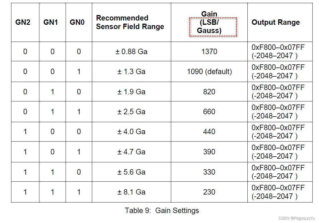
自测校准模式触发HMC5883L自动进行两次测试,第一次测试环境三轴的磁强度,然后在每轴上增加1.1高斯量,再测试三轴的磁强度,然后将结果相减得到绝对变化量,也就是对应1.1高斯的实际变量化,而1.1高斯量的理论变化量可以通过设定的增益等级对应的单位高斯变化量计算而得。从而可以得到每轴的校准系数=理论变化量/实际变化量。
温度校准模式可以在温度变化产生影响时,将不同温度T1的测试值回归到特定温度T0的对应值。在T0温度做自检测试得到对应1.1高斯变化的检测数值变化量,而在T1温度做自检测试也得到对应1.1高斯变化的检测数值变化量,由于温度不同产生的影响,这两个数值变化量不同,因此可以产生温度校准系数=value(T0)/value(T1), 将T1温度的检测值乘以系数,就得到如果是在T0温度做测试会得到的结果值。
测试效果
串口打印输出的效果如下:
校准扩展
可以基于实际环境和应用进行进一步的校准,如在设定的一些角度位如0度,45,90度,135度,180度,225度,270度,315度进行角度测试,将结果和理论值比较,从而再次产生分段校准系数。一般针对水平面运动精度就已足够。如果涉及三维运动,则要进行更复杂的转换和校准。
例程下载
STM32G030模拟I2C协议获取HMC5883L电子罗盘磁角度数据 (HAL)例程
–End–


![[4]PCB设计实验|LPWAN物联网系统解决方案 |LoRa模块/LoRa网关/云平台/LoRa应用案例|9:30~10:00](https://img-blog.csdnimg.cn/6cb9d7d0af104fd9862817ac73ef30bb.png)