ArduPilot开源代码之H743+BMI270x2+ChibiOS配置适配
- 1. 源由
- 2. 配置适配
- 2.1 bootloader配置
- 2.2 flight controller配置
- 3. 4.3.6固件编译
- Step 1: 获取源代码
- Step 2: 准备编译环境
- Step 3: 复制配置文件
- Step 4: 编译bootloader
- Step 5: 编译飞控
- 4. 基础配置
- 4.1 机型配置
- 4.2 IMU校准
- 4.3 电机校准
- 4.4. ELRS接收机
- 4.5 飞行模式配置
- 4.6 功能配置
- 5. 总结
- 6. 参考资料
1. 源由
Betaflight转ArduPilot飞行,体验更好的GCS控制体验。
目前,模型的配置情况:
- Mark4
- H743 BMI270 x 2
- EFM8 Bluejay
- Motor 2205 2450RPM x 4
- GPS BN880
- CRSF Receiver
- mavlink esp32
- FOXEER Toothless 2
- PandaRC VT5804M L1 (Buzzer/Mic/IRC Protocol) 5.8G
飞控硬件实际情况:
- 控制器:STM32H743VI H6
- 陀螺仪:BMI270
- 气压计:DPS310
- 黑匣子:128MB
- PWM输出:10CH
- 舵机输出:2CH
- 通用串口:8CH
- 输入电源:3-6SLipo
- 输出电源:5V/2.5A, 9V/3A
- 重量:8.8g
- 外形尺寸:37mm x 37mm
- 安装孔位:30.5mm x 30.5mm
2. 配置适配
根据Matek H743和原厂AOCODARC配置文件,通过对ArduPilot硬件配置文件的学习和22轮实践,调试/验证,H743-BMI270x2-v22.zip。
将每行的内容,尽量结合配置文件给出描述,详细开发文档详见:Porting to a new flight controller board
2.1 bootloader配置
# hw definition file for processing by chibios_pins.py
#

# MCU class and specific type
MCU STM32H7xx STM32H743xx

# board ID for firmware load
APJ_BOARD_ID 1018

# crystal frequency, setup to use external oscillator
OSCILLATOR_HZ 8000000

FLASH_SIZE_KB 2048

# bootloader starts at zero offset
FLASH_RESERVE_START_KB 0

# use last 2 pages for flash storage
# H743 has 16 pages of 128k each
STORAGE_FLASH_PAGE 14

# the location where the bootloader will put the firmware
# the H743 has 128k sectors
FLASH_BOOTLOADER_LOAD_KB 128


# order of UARTs (and USB). Allow bootloading on USB and telem1
SERIAL_ORDER OTG1 #UART7

# UART7 (telem1)
#PE7 UART7_RX UART7 NODMA
#PE8 UART7_TX UART7 NODMA

# PA10 IO-debug-console
PA11 OTG_FS_DM OTG1
PA12 OTG_FS_DP OTG1

PA13 JTMS-SWDIO SWD
PA14 JTCK-SWCLK SWD

PE3 LED_BOOTLOADER OUTPUT LOW
define HAL_LED_ON 0

# Add CS pins to ensure they are high in bootloader
PC15 IMU1_CS CS
PB12 MAX7456_CS CS
PE11 IMU2_CS CS
PD3  FLASH_CS CS
2.2 flight controller配置
# hw definition file for processing by chibios_pins.py
# for AOCODARC H743 Dual, and it's for Daniel's copter:
# Version 22: BMI270 + DPS310 + X8(4 motor with bddshot used)

# This hwdef.dat file contains a lot of comments so it can act as a
# reference for developers adding new boards.

# The hwdef.dat file defines all the hardware peripherals and pins for
# a port of ArduPilot to a board using the ChibiOS HAL. You should be
# able to write the hwdef.dat file for a new board with just the
# schematic for the board.

# This file is processed by chibios_hwdef.py to create hwdef.h for
# this board. You may find it useful to run chibios_hwdef.py manually
# when building this file for a new board. The resulting hwdef.h file
# is formatted to make it quite readable. It is strongly suggested
# that you read the resulting hwdef.h file when porting to a new board
# to make sure it has resulted in what you want.

# You should read this file in conjunction with the schematic for your
# board, the datasheet for the MCU for your board and the python
# tables file that we have extracted from the datasheet for your
# MCU. The python tables file is particularly important, so if you
# haven't seen it before go and look at it now. For the STM32F427 it
# it called STM32F427xx.py and it is in the hwdef/script/ directory
# inside the HAL_ChibiOS directory. That file tells you what each pin
# can do (the alternate functions table) and what DMA channels can be
# used for each peripheral type. The alternative functions table is
# particularly useful when doing a new hwdef.dat file as you can work
# out peripheral numbers given a port/pin name.

# We need to start off by saying what main CPU is on the board. There
# are two CPU identifiers that you need to specify. The first is the
# ChibiOS MCU type. The second string needs to match the name of a config
# file in the libraries/AP_HAL_ChibiOS/hwdef/script directory.
# In this case we are using a H743 MCU, so we select STM32H743xx to match the
# STM32H743xx.py file in the script directory. If you are supporting a
# board type that doesn't have a python hardware database file yet
# then you will need to create one. There are scripts in the scripts
# directory to help with that by parsing the STM32 datasheets to
# extract the required DMA and alternate function tables.

# MCU class and specific type
MCU STM32H7xx STM32H743xx

# Now we need to specify the APJ_BOARD_ID. This is the ID that the
# bootloader presents to GCS software so it knows if this firmware is
# suitable for the board. Please see
# https://github.com/ArduPilot/Bootloader/blob/master/hw_config.h for
# a list of current board IDs. If you add a new board type then please
# get it added to that repository so we don't get conflicts.

# Note that APJ is "ArduPilot JSON Firmware Format".

# board ID for firmware load
APJ_BOARD_ID 1018

# Now you need to say what crystal frequency you have for this
# board. All of the clocks are scaled against this. Typical values are
# 24000000 or 8000000.

# crystal frequency, setup to use external oscillator
OSCILLATOR_HZ 8000000

# Now the size of flash in kilobytes, for creating the ld.script.

# flash size
FLASH_SIZE_KB 2048

env OPTIMIZE -Os

# bootloader takes first sector
FLASH_RESERVE_START_KB 128

# On some boards you will need to also set the various PLL values. See
# the defaults in common/mcuconf.h, and use the define mechanism
# explained later in this file to override values suitable for your
# board. Refer to your MCU datasheet or examples from supported boards
# in ChibiOS for the right values.

# Now define the voltage the MCU runs at. This is needed for ChibiOS
# to set various internal driver limits. It is in 0.01 volt units.


# This is the STM32 timer that ChibiOS will use for the low level
# driver. This must be a 32 bit timer. We currently only support
# timers 2, 3, 4, 5 and 21. See hal_st_lld.c in ChibiOS for details.

# ChibiOS system timer
STM32_ST_USE_TIMER 12
define CH_CFG_ST_RESOLUTION 16

# Now define which UART is used for printf(). We rarely use printf()
# in ChibiOS, so this is really only for debugging very early startup
# in drivers.

# Serial port for stdout. This is optional. If you leave it out then
# output from printf() lines will go to the ArduPilot console, which is the
# first UART in the SERIAL_ORDER list.  But note that some startup code
# runs before USB is set up.
# The value for STDOUT_SERIAL is a serial device name, and must be for a
# serial device for which pins are defined in this file. For example, SD7
# is for UART7 (SD7 == "serial device 7" in ChibiOS).
#STDOUT_SERIAL SD7
#STDOUT_BAUDRATE 57600

# Now the USB setup, if you have USB. All of these settings are
# option, and the ones below are the defaults. It ends up creating a
# USB ID on Linux like this:
# /dev/serial/by-id/usb-ArduPilot_fmuv3_3E0031000B51353233343932-if00
# If creating a board for a RTF vehicle you may wish to customise these.

# USB setup
USB_STRING_MANUFACTURER "DanielDual"

# Now we define the pins that USB is connected on.
PA11 OTG_FS_DM OTG1
PA12 OTG_FS_DP OTG1

# OTG USB Detect
PE2 EXT_CS2 CS

# These are the pins for SWD debugging with a STlinkv2 or black-magic probe.
PA13 JTMS-SWDIO SWD
PA14 JTCK-SWCLK SWD

# Now the first SPI bus. At minimum you need SCK, MISO and MOSI pin
# definitions. You can add speed modifiers if you want them, otherwise
# the defaults for the peripheral class are used.

# SPI1 for IMU1 (BMI270)
PC15 IMU1_CS CS
PA5 SPI1_SCK SPI1
PA6 SPI1_MISO SPI1
PD7 SPI1_MOSI SPI1

# This is the invensense data-ready pin. We don't use it in the
# default driver.
#PB2 MPU_DRDY INPUT

# SPI2 for MAX7456 OSD
PB12 MAX7456_CS CS
PB13 SPI2_SCK SPI2
PB14 SPI2_MISO SPI2
PB15 SPI2_MOSI SPI2

# This is the invensense data-ready pin. We don't use it in the
# default driver.
#PE15 MPU_DRDY INPUT

# SPI3 for SPI flash - W25N01GV
PD3 FLASH_CS CS
PB3 SPI3_SCK SPI3
PB4 SPI3_MISO SPI3
PB5 SPI3_MOSI SPI3

# SPI4 for IMU2 (BMI270)
PE11 IMU2_CS CS
PE12 SPI4_SCK SPI4
PE13 SPI4_MISO SPI4
PE14 SPI4_MOSI SPI4

# Now define the order that I2C buses are presented in the hal.i2c API
# in ArduPilot. For historical reasons inherited from HAL_PX4 the
# 'external' I2C bus should be bus 1 in hal.i2c, and internal I2C bus
# should be bus 0. On fmuv3 the STM32 I2C1 is our external bus and
# I2C2 is our internal bus, so we need to setup the order as I2C2
# followed by I2C1 in order to achieve the conventional order that
# drivers expect.

# two I2C bus, order of I2C buses
I2C_ORDER I2C2 I2C1

# Now the first I2C bus. The pin speeds are automatically setup
# correctly, but can be overridden here if needed.

# I2C1
PB6 I2C1_SCL I2C1
PB7 I2C1_SDA I2C1

# I2C2
PB10 I2C2_SCL I2C2
PB11 I2C2_SDA I2C2

# Now define the primary battery connectors. The labels we choose here
# are used to create defines for pins in the various drivers, so
# choose names that match existing board setups where possible. Here
# we define two pins PA2 and PA3 for voltage and current sensing, with
# a scale factor of 1.0 and connected on ADC1. The pin number this
# maps to in hal.adc is automatically determined using the datasheet
# tables in STM32F427xx.py.

# ADC for Power
PC0 BATT_VOLTAGE_SENS ADC1 SCALE(1)
PC1 BATT_CURRENT_SENS ADC1 SCALE(1)

# This adds a C define which sets up the ArduPilot architecture
# define. Any line starting with 'define' is copied literally as
# a #define in the hwdef.h header.

# Now setup the default battery pins driver analog pins and default
# scaling for the power brick.

define HAL_BATT_MONITOR_DEFAULT 4
define HAL_BATT_VOLT_PIN 10
define HAL_BATT_CURR_PIN 11
define HAL_BATT_VOLT_SCALE 11.0
define HAL_BATT_CURR_SCALE 40.0

# ADC for airspeed
PC4 PRESSURE_SENS ADC1 SCALE(2)
define HAL_DEFAULT_AIRSPEED_PIN 4

# ADC for rssi
PC5 RSSI_ADC ADC1
define BOARD_RSSI_ANA_PIN 8

# Define a LED, mapping it to GPIO(0). LOW will illuminate the LED
# PE12 FMU_LED_AMBER OUTPUT HIGH OPENDRAIN GPIO(0)
# green LED1 marked as B/E
# blue LED0 marked as ACT
PE3 LED0 OUTPUT LOW GPIO(90) # blue
PE4 LED1 OUTPUT LOW GPIO(91) # orange
define HAL_GPIO_A_LED_PIN 91
define HAL_GPIO_B_LED_PIN 90
define HAL_GPIO_LED_OFF 1

# Now the serial ordering. These map to the SERIALn_ parameter numbers
# If you use a shorter list then HAL_Empty::UARTDriver
# objects are substituted for later UARTs, or you can leave a gap by
# listing one or more of the uarts as EMPTY.

# The normal usage of this ordering is:
# 1) SERIAL0: console (primary mavlink, usually USB)
# 2) SERIAL1: Telemetry
# 3) SERIAL2: Optical Flow
# 4) SERIAL3: GPS
# 5) SERIAL4: VTX
# 6) SERIAL5: ESC Telemetry
# 7) SERIAL6: spare
# 8) SERIAL7: RC input

# order of UARTs (and USB)
SERIAL_ORDER OTG1 UART4 UART8 USART2 USART3 USART6 UART7 USART1

# Now we start on the pin definitions. Every pin used by ArduPilot
# needs to be in this file. The pins in this file can be defined in any order.

# The format is P+port+pin. So PC4 is portC pin4.
# For every pin the second column is the label. If this is a
# peripheral that has an alternate function defined in the STM32
# datasheet then the label must be the name of that alternative
# function. The names are looked up in the python database for this
# MCU. Please see STM32F427xx.py for the F427 database. That database
# is used to automatically fill in the alternative function (and later
# for the DMA channels).

# The third column is the peripheral type. This must be one of the
# following: UARTn, USARTn, OTGn, SPIn, I2Cn, ADCn, TIMn, SWD, SDIO,
# INPUT, OUTPUT, CS.

# The fourth and later columns are for modifiers on the pin. The
# possible modifiers are:
# pin speed: SPEED_VERYLOW, SPEED_LOW, SPEED_MEDIUM, SPEED_HIGH
# pullup: PULLUP, PULLDOWN, FLOATING
# out type: OPENDRAIN, PUSHPULL
# default value: LOW, HIGH

# Additionally, each class of pin peripheral can have extra modifiers
# suitable for that pin type. For example, for an OUTPUT you can map
# it to a GPIO number in hal.gpio using the GPIO(n) modifier. For ADC
# inputs you can apply a scaling factor (to bring it to unit volts)
# using the SCALE(x) modifier. See the examples below for more
# modifiers, or read the python code in chibios_hwdef.py.

# Now we define UART4 which is for the GPS. Be careful
# of the difference between USART and UART. Check the STM32F427xx.py
# if unsure which it is. For a UART we need to specify at least TX and
# RX pins.

# USART1 (RC input), SERIAL7
PA9  USART1_TX USART1 NODMA
PA10 TIM1_CH3 TIM1 RCININT PULLDOWN LOW

# as an alternative config setup the RX6 pin as a uart. This allows
# for bi-directional UART based receiver protocols such as FPort
# without any extra hardware
PA10 USART1_RX USART1 NODMA ALT(1)

# This sets up the UART for talking to the IOMCU. Note that it is
# vital that this UART has DMA available. See the DMA settings below
# for more information.

# USART2 (GPS), SERIAL3
PD5 USART2_TX USART2
PD6 USART2_RX USART2

# USART3 (VTX), SERIAL4
PD8 USART3_TX USART3 NODMA
PD9 USART3_RX USART3 NODMA

# UART4 (Telemetry), SERIAL1
PB8 UART4_RX UART4 NODMA
PB9 UART4_TX UART4 NODMA

# USART6 (ESC Telemetry), SERIAL5*
PC6 USART6_TX USART6
PC7 USART6_RX USART6

# UART7 (spare), SERIAL6*
PE7 UART7_RX UART7 NODMA
PE8 UART7_TX UART7 NODMA

# UART8 (Optical Flow), SERIAL2
PE0 UART8_RX UART8 NODMA
PE1 UART8_TX UART8 NODMA

# Now we start defining some PWM pins. We also map these pins to GPIO
# values, so users can set BRD_PWM_COUNT to choose how many of the PWM
# outputs on the primary MCU are setup as PWM and how many as
# GPIOs. To match HAL_PX4 we number the GPIOs for the PWM outputs
# starting at 50.

# Motors
PB0  TIM3_CH3 TIM3  PWM(1)  GPIO(50) BIDIR
PB1  TIM3_CH4 TIM3  PWM(2)  GPIO(51)
PA0  TIM2_CH1 TIM2  PWM(3)  GPIO(52) BIDIR
PA1  TIM2_CH2 TIM2  PWM(4)  GPIO(53)
PA2  TIM5_CH3 TIM5  PWM(5)  GPIO(54) BIDIR
PA3  TIM5_CH4 TIM5  PWM(6)  GPIO(55)
PD12 TIM4_CH1 TIM4  PWM(7)  GPIO(56) BIDIR
PD13 TIM4_CH2 TIM4  PWM(8)  GPIO(57)


# This defines the PWM pin for the buzzer (if there is one). It is
# also mapped to a GPIO output so you can play with the buzzer via
# MAVLink relay commands if you want to.

# PWM output for buzzer/Beeper
PA15 BUZZER OUTPUT GPIO(32) LOW
define HAL_BUZZER_PIN 32

# This defines a couple of general purpose outputs, mapped to GPIO
# numbers 1 and 2 for users.

# GPIOs for pinio
PD10  PINIO1 OUTPUT GPIO(81) LOW
PD11  PINIO2 OUTPUT GPIO(82) LOW

# DMA Priority
DMA_PRIORITY SPI1* SPI4*
DMA_NOSHARE SPI1* SPI4* TIM3* TIM2* TIM5* TIM4*

# use last 2 pages for flash storage
# H743 has 16 pages of 128k each
STORAGE_FLASH_PAGE 14
define HAL_STORAGE_SIZE 32768

# Now the SPI device table. This table creates all accessible SPI
# devices, giving the name of the device (which is used by device
# drivers to open the device), plus which SPI bus it it on, what
# device ID will be used (which controls the IDs used in parameters
# such as COMPASS_DEV_ID, so we can detect when the list of devices
# changes between reboots for calibration purposes), the SPI mode to
# use, and the low and high speed settings for the device.

# You can define more SPI devices than you actually have, to allow for
# flexibility in board setup, and the driver code can probe to see
# which are responding.

# The DEVID values and device names are chosen to match the PX4 port
# of ArduPilot so users don't need to re-do their accel and compass
# calibrations when moving to ChibiOS.

# spi devices
SPIDEV bmi270_1      SPI1 DEVID1 IMU1_CS      MODE3 10*MHZ 10*MHZ
SPIDEV bmi270_2      SPI4 DEVID1 IMU2_CS      MODE3 10*MHZ 10*MHZ
SPIDEV dataflash     SPI3 DEVID1 FLASH_CS     MODE3 104*MHZ 104*MHZ
SPIDEV osd           SPI2 DEVID4 MAX7456_CS   MODE0  10*MHZ 10*MHZ

# two IMUs
IMU BMI270 SPI:bmi270_1 ROTATION_ROLL_180_YAW_90
IMU BMI270 SPI:bmi270_2 ROTATION_ROLL_180

# DPS310 integrated on I2C2 bus, multiple possible choices for external barometer
BARO DPS310 I2C:0:0x76

# no built-in compass, but probe the i2c bus for all possible
# external compass types
define ALLOW_ARM_NO_COMPASS
define HAL_PROBE_EXTERNAL_I2C_COMPASSES
define HAL_I2C_INTERNAL_MASK 0
define HAL_COMPASS_AUTO_ROT_DEFAULT 2

# setup for OSD
define OSD_ENABLED 1
define HAL_OSD_TYPE_DEFAULT 1
ROMFS_WILDCARD libraries/AP_OSD/fonts/font*.bin

# enable logging to dataflash
define HAL_LOGGING_DATAFLASH_DRIVER AP_Logger_W25N01GV
3. 4.3.6固件编译
Step 1: 获取源代码
# git clone https://github.com/ArduPilot/ardupilot.git
# git checkout Copter-4.3.6
# git submodule update --init --recursive
Step 2: 准备编译环境
详见:ArduPilot飞控AOCODARC-H7DUAL固件编译
注:正式编译前,最好清理下./waf distclean。
Step 3: 复制配置文件
将H743-BMI270x2-v22.zip解压,移动到libraries\AP_HAL_ChibiOS\hwdef目录下
Step 4: 编译bootloader
./Tools/scripts/build_bootloaders.py H743_BMI270x2_v22
Step 5: 编译飞控
首先,同步下子模块的同步,确保所有子模块都已经下载到本地后,再开始编译。
# ./Tools/gittools/submodule-sync.sh
根据配置文件对飞控进行配置,生成相应的头文件。
# ./waf configure --board H743_BMI270x2_v22
编译飞控固件
# ./waf copter
4. 基础配置
4.1 机型配置
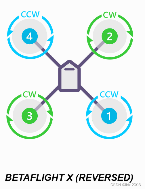
根据模型进行配置,笔者是X型的反装电机。因为是从Betaflight转过来,可以认为是Betaflight X reversed配置。
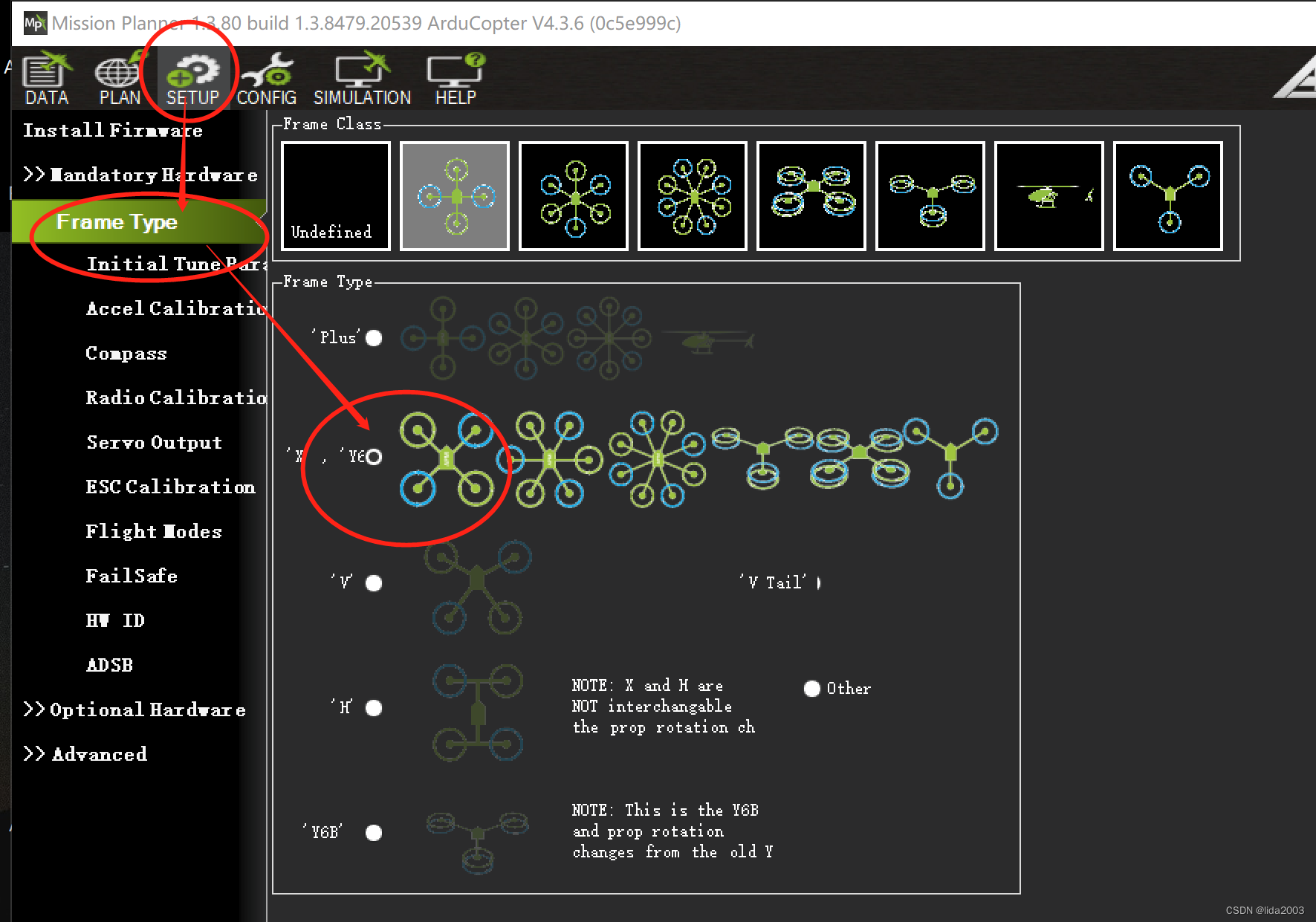
笔者是选择了Betaflight配置构型。
需要进一步,确认一下参数是否正确。
FRAME_CLASS = 1 //quad
FRAME_TYPE = 18 // betaflight x reversed
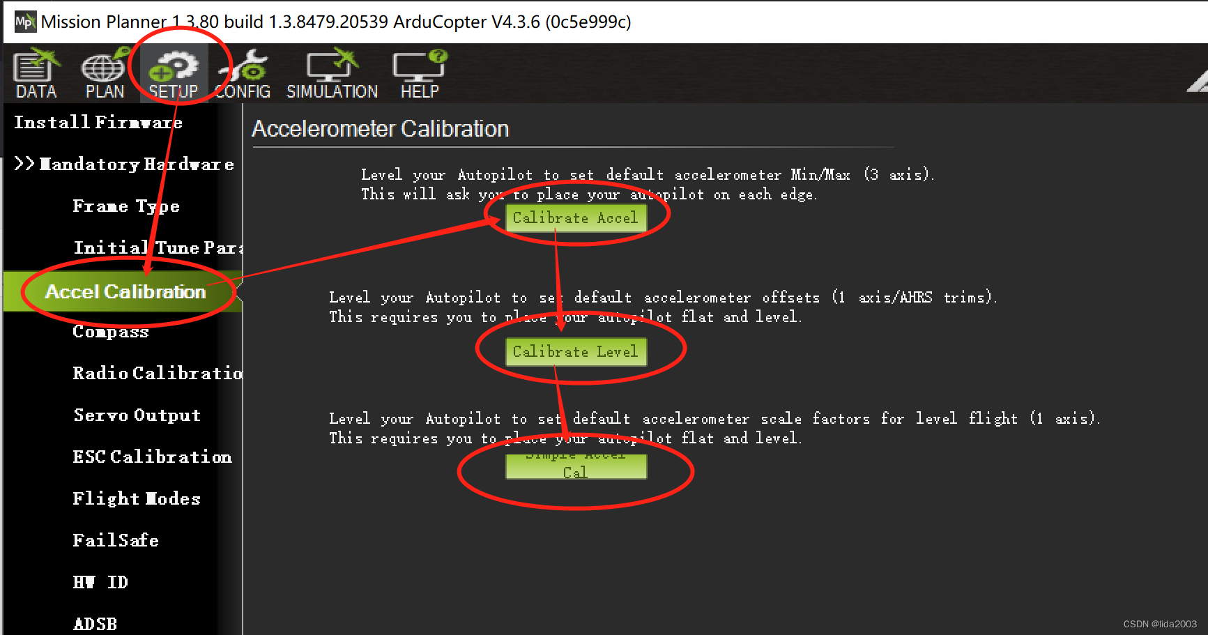
4.2 IMU校准
因为是双IMU,所以请确认一下参数是否使用正确的配置。
EK3_IMU_MASK = 3 //表示使用两个IMU硬件
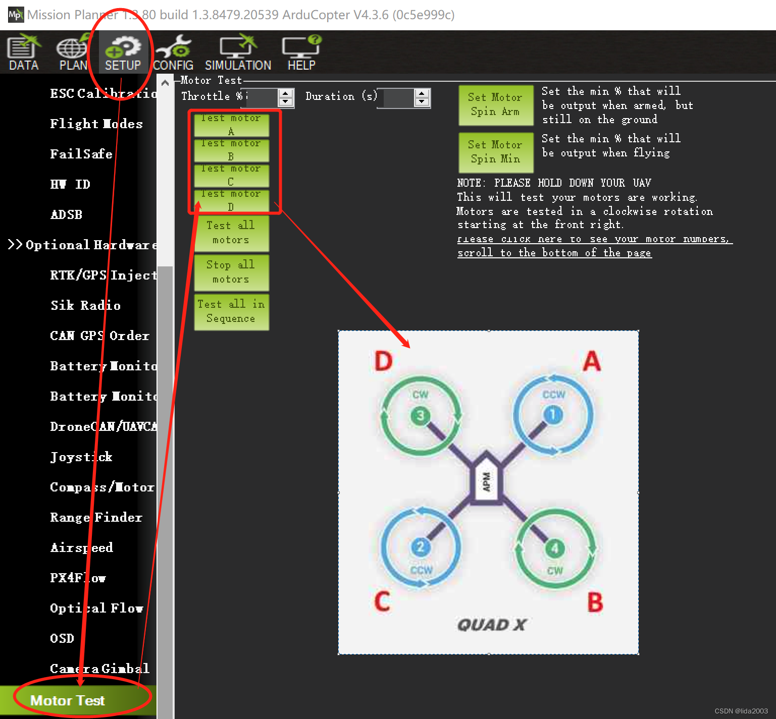
4.3 电机校准
笔者使用的是BlueJay固件,支持bi-directional dshot600。
注:这里从配置的角度是这么设置的,但是目前尚未看到双向dshot给出的RPM值。
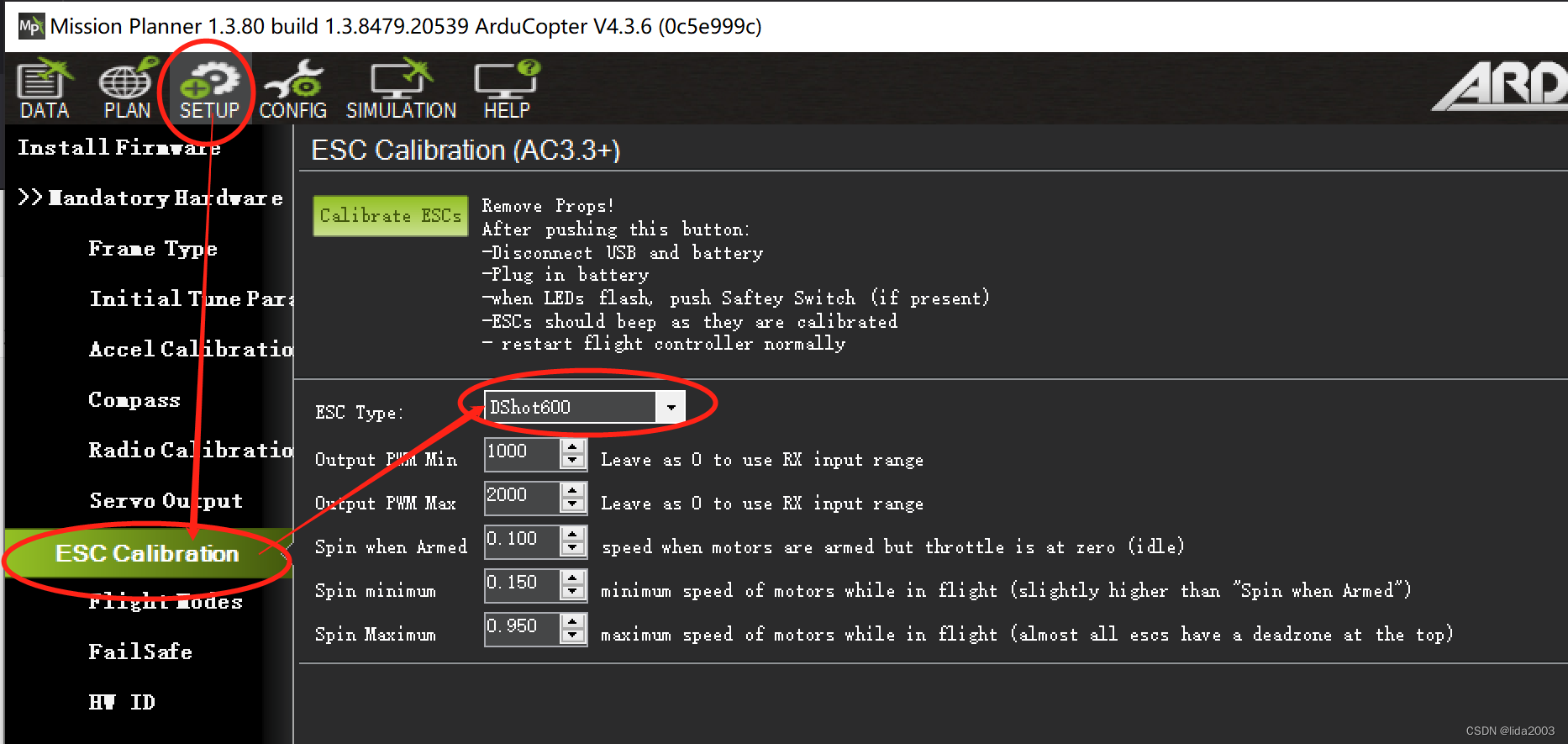
后台参数请确认:
SERIAL5_PROTOCOL = 16 //ESC telemetry
MOT_PWM_TYPE 6 // Dshot600
SERVO_BLH_AUTO 1
SERVO_BLH_TRATE 10 //10Hz
SERVO_BLH_BDMASK 15
SERVO_BLH_POLES 12
SERVO_BLH_OTYPE 6 //dshot600
SERVO_DSHOT_ESC 2 //BLHeli_S
SERVO_DSHOT_RATE 0 //default 1khz
对于电机测试顺序如下:
注:要确保顺序一致,如有问题,请不要起飞,因为肯定飞不起来的。
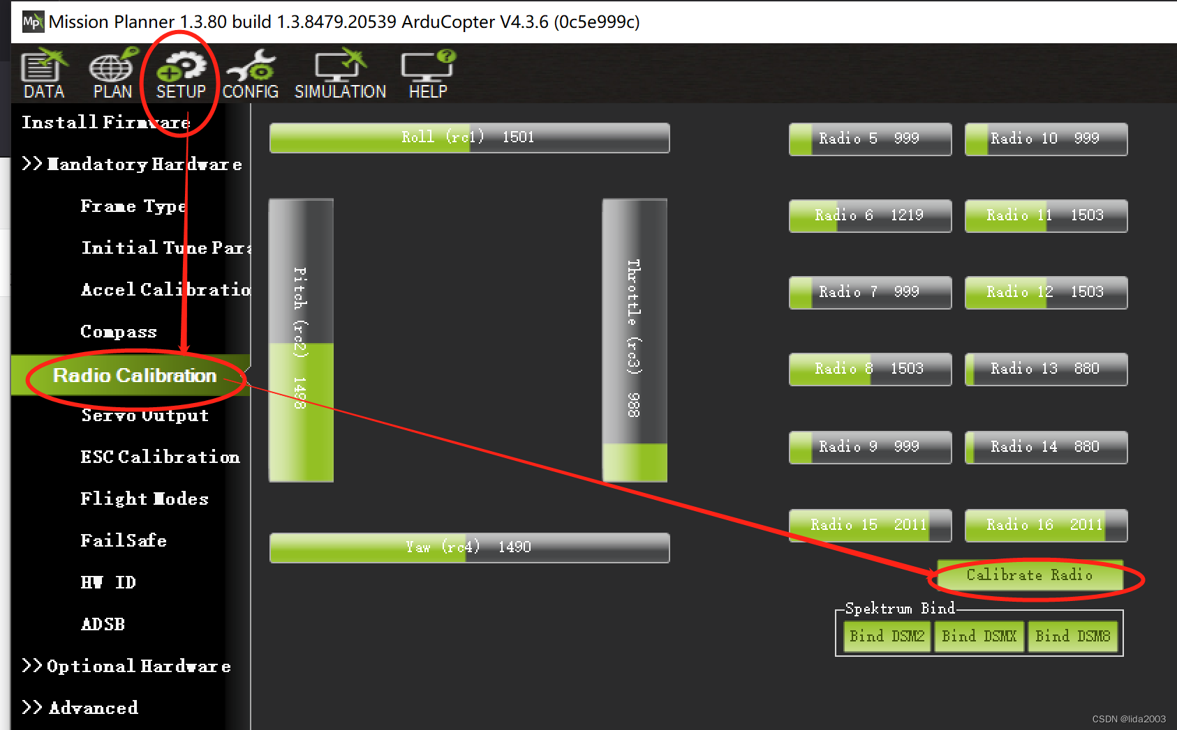
4.4. ELRS接收机
BRD_ALT_CONFIG 1
SERIAL7_PROTOCOL = 23
SERIAL7_OPTIONS = 0
RC_PROTOCOLS = 1
RSSI_TYPE = 3
RC_OPTIONS 544 //RC_OPTIONS turn on Bit 9th which is “Suppress CRSF mode/rate message for ELRS systems”.
SERIAL7_BAUD = 115
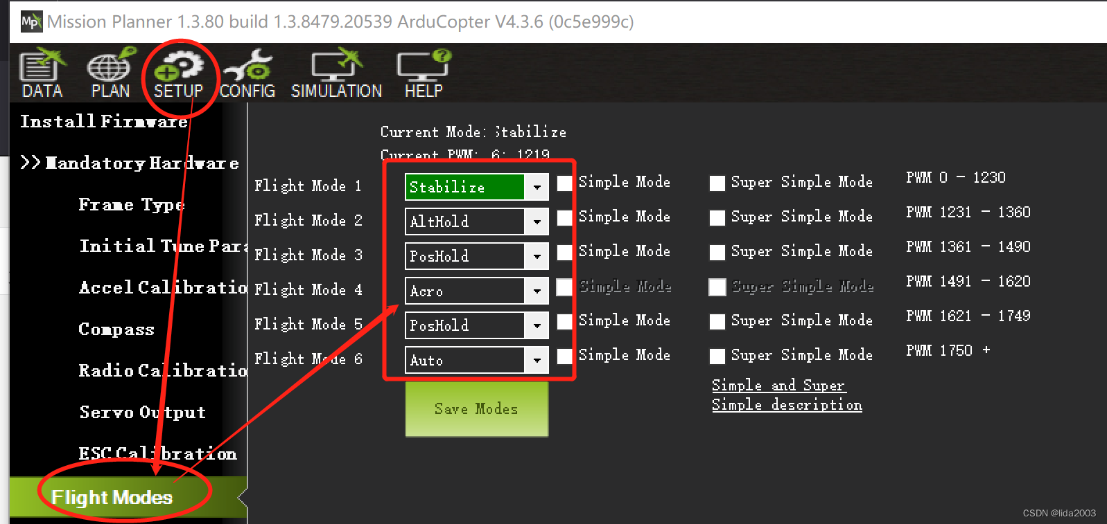
4.5 飞行模式配置
请根据各自遥控器上的设置选择哪个通道作为飞行模式。
FLTMODE_CH 6
注:笔者采用TX12配置A+C,进行6个模式选择。
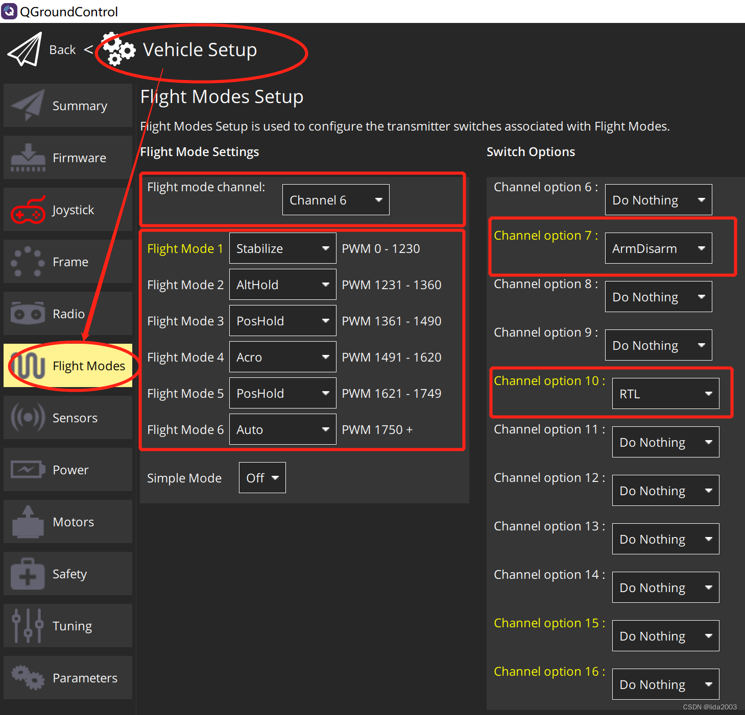
4.6 功能配置
QGC功能在遥控设置这块比较好,因此,推荐设置【RTL】和【ArmDisarm】功能。
5. 总结
上述配置,经过实际试飞:
【1】稳定悬停;
【2】前进/后退/左倾/右倾正常;
【3】电压显示正常
【4】磁力计正常
【5】GPS正常
已知问题:
【1】VTX尚不能正常工作
【2】飞控直接上电启动连MP,姿态显示异常(先连QGC再连MP正常)
【3】双向Dshot似乎并未正常工作,RPM转速未在MP上看到
【4】mavlink esp32尚未启用
鉴于目前资源缺少,从厂家和ArduPilot官方反馈的技术信息有限,可能需要折腾一段时间。
注:后续会继续更新,确保整体功能正常,合适远航位置!
6. 参考资料
【1】BetaFlight Mark4 H7 Dual270 + BN880 + CRSF 配置存档
【2】ArduPilot硬件AOCODARC H7DUAL配置文件讨论
【3】ArduPilot飞控AOCODARC-H7DUAL固件编译
【4】ArduPilot Kakute F7 AIO DIYF450 without GPS配置
【5】ArduPilot: Porting to a new flight controller board
【6】ArduPilot: esc-calibration
【7】ArduPilot: common-dshot-escs