CenterFusion数据处理函数__getitem__解析
- 1. 图像数据处理
- 1.1 通过利用nuScence_COCO实例化对象获取图像以及相关数据的信息
- 1.2 获取图像数据增强的相关参数:中心点c,尺度scale,旋转rotia和翻转flip
- 1.3 根据生成的参数生成仿射矩阵来对图像进行仿射变换
- 1.4 生成的仿射变换后的图像进行图像增强
- 2. 点云数据处理
- 2.1 从image_info中加载点云数据
- 2.2 将点云都投影到仿射变换后的图像坐标系,同时对图像外的点进行过滤
- 2.3 生成柱状体,同时将柱状体投影到仿射变换后的图像坐标系
- 2.4 根据柱状体生成雷达特征
- 3. anns标注数据的处理
- 4. __getitem__(self, index)代码注释总结
CenterFusion的数据处理函数__getitem__()在/Centerfusion/src/lib/dataset/datasets/generic_dataset.py下的GenericDataset类中
在经过convert_nuScenes.py后会生成nuScence_COCO格式的json文件,分别为train.json, val.json, mini_train.json, mini_val.json, test.json这五个文件(这里顺便提一下由于生成的train.json和val.json比较大所以在训练的时候需要比较多的内存来加载这两个数据集,如果是申请的云服务器或者docker需要多申请一些内存,应该在80G以上可以满足需求(五一训练时内存占用在70G以上80G以下)。这里调试过程使用的是mini_train.json和mini_val.json)
接下来主要分析__getitem__()这个函数,该函数在generic_dataset.py文件的99行,该函数分为图像处理部分和点云处理部分
1. 图像数据处理
1.1 通过利用nuScence_COCO实例化对象获取图像以及相关数据的信息
getitem()函数,\CenterFusion\src\lib\dataset\generic_dataset.py文件的99行
def __getitem__(self, index):
  opt = self.opt  # 获取参数配置
  img, anns, img_info, img_path = self._load_data(index)  # 加载图像数据、标注数据、图像信息和图像路径
  '''
  加载图像、标注信息、图像信息和图像路径
  img(图像), anns(标注信息), image_info(图像信息), img_path(图像路径)
  '''
  height, width = img.shape[0], img.shape[1] # 获取图像高度和宽度
首先介绍_load_data()函数,该函数在generic_dataset.py文件的225行,该函数根据传入的index来获取coco实例中的数据,在GenericDataset类的初始化中,已经初始化了一个nuScence_COCO数据集对象。
ps:nuScence_COCO数据集对象详见->CenterFusion数据集nuScence_COCO格式
def _load_data(self, index):
  coco = self.coco
  img_dir = self.img_dir
  img_id = self.images[index]
  img, anns, img_info, img_path = self._load_image_anns(img_id, coco, img_dir)

  return img, anns, img_info, img_path
其中调用了_load_image_anns()函数,该函数在generic_dataset.py文件的216行
def _load_image_anns(self, img_id, coco, img_dir):
  img_info = coco.loadImgs(ids=[img_id])[0]
  '''
  详见-> https://blog.csdn.net/qq_34972053/article/details/130620003
    "images": [{"id": int,                             #图片ID
                "file_name": "文件路径",                #图片文件相对路径,相对于当前文件的上一级目录
                "calib": [3x4矩阵],                     #摄像头内外参标定矩阵
                "video_id": int,                       #对应"video"key中的ID
                "frame_id": int,                       #对应的视频帧数
                "sensor_id": 1,                        #对应的摄像头ID,取值范围1-6,顺序为'CAM_FRONT', 'CAM_FRONT_RIGHT', 'CAM_BACK_RIGHT', 'CAM_BACK', 'CAM_BACK_LEFT', 'CAM_FRONT_LEFT'
                "sample_token": "",                    #记录该场景的具体的一个sample的token值
                "trans_matrix": [4x4矩阵],              #世界坐标系到相机坐标系的转换矩阵  刚体变换
                "velocity_trans_matrix": [4x4矩阵],     #世界坐标系到相机坐标系的速度转换矩阵
                "width": int,                          #图片像素宽度
                "height": int,                         #图片像素高度
                "pose_record_trans": [1x3矩阵],         #世界坐标系到车辆坐标系平移矩阵
                "pose_record_rot": [1x4矩阵],           #世界坐标系到车辆坐标系旋转矩阵
                "cs_record_trans": [1x3矩阵],           #车辆坐标系到摄像头坐标系平移矩阵
                "cs_record_rot": [1x4矩阵],             #车辆坐标系到摄像头坐标系旋转矩阵
                "radar_pc": [18x123矩阵],               #该场景及之前3sweep的雷达点云信息x y z dyn_prop id rcs vx vy vx_comp vy_comp is_quality_valid ambig_state x_rms y_rms invalid_state pdh0 vx_rms vy_rms
                "camera_intrinsic": [3x3矩阵]           #相机内参矩阵
                }
  '''
  file_name = img_info['file_name']
  img_path = os.path.join(img_dir, file_name)
  ann_ids = coco.getAnnIds(imgIds=[img_id])
  anns = copy.deepcopy(coco.loadAnns(ids=ann_ids))
  '''
  详见-> https://blog.csdn.net/qq_34972053/article/details/130620003
  "annotations": [{"id": int,                      #annotation ID
                 "image_id": int,               #对应"images"中的ID
                 "category_id": int,            #对应"categories"中类别的ID
                 "dim": [1x3矩阵],               #h高/w宽/l长,单位m
                 "location": [1x3矩阵],          #前两项为xy中心点坐标位置,单位m,第三项与"depth"相同为box的深度
                 "depth": double,               #box的深度
                 "occluded": 0,                 #0  交通堵塞
                 "truncated": 0,                #0  截断(卡帧)
                 "rotation_y": ,                #标注目标yaw角
                 "amodel_center": [1x2矩阵],     #标注目标中心点像素坐标xy
                 "iscrowd": 0,                  #0  是否有人群
                 "track_id": int,               #目标跟踪ID
                 "attributes": int,             #对应"attributes"中目标运动属性ID
                 "bbox": [1x4矩阵],              #像素坐标系下标注数据x,y,w,h
                 "area": double,                #像素坐标系下标注面积
                 "alpha": double                #在相机坐标系中的旋转角度,范围 [-pi..pi]
                }
  '''
  img = cv2.imread(img_path)
  return img, anns, img_info, img_path
通过以上两个函数就获得了img(图像), anns(标注信息), image_info(图像信息), img_path(图像路径)。
1.2 获取图像数据增强的相关参数:中心点c,尺度scale,旋转rotia和翻转flip
继续分析分析__getitem__()函数,\CenterFusion\src\lib\dataset\generic_dataset.py文件的104行:
    ## 根据深度从远到近对标注信息进行排序
    new_anns = sorted(anns, key=lambda k: k['depth'], reverse=True)

    ## 从图像中获取原始图像的中心和比例
    # 中心点
    c = np.array([img.shape[1] / 2., img.shape[0] / 2.], dtype=np.float32)
    # 比例尺度,取图像较大的一边作为基准,如果未设置not_max_crop参数,尺度为图像宽高,否则按照not_max_crop的设置取尺度
    s = max(img.shape[0], img.shape[1]) * 1.0 if not self.opt.not_max_crop \
      else np.array([img.shape[1], img.shape[0]], np.float32)
    # 数据增强参数,包括尺度、旋转和是否翻转
    aug_s, rot, flipped = 1, 0, 0

    ## 训练集的数据增强
    if 'train' in self.split:
      c, aug_s, rot = self._get_aug_param(c, s, width, height) # 计算中心点、尺度和旋转角度的增强参数
      s = s * aug_s # 更新比例
      ## 判断是否要对图像进行垂直翻转
      if np.random.random() < opt.flip:  # 随机翻转
        flipped = 1 # 记录当前img是否flipped
        img = img[:, ::-1, :]
        anns = self._flip_anns(anns, width) # 翻转标注信息
其中调用了_get_aug_param()函数,该函数在generic_dataset.py文件的319行
def _get_aug_param(self, c, s, width, height, disturb=False):
  if (not self.opt.not_rand_crop) and not disturb:
    '''
    如果对图像进行裁剪的话,
    首先生成一个新的aug_s(比例是一个小数),
    之后分别在宽高方向生成裁剪的大小,
    最后在裁剪的区域内生成新的中心点
    '''
    aug_s = np.random.choice(np.arange(0.6, 1.4, 0.1))
    w_border = self._get_border(128, width)
    h_border = self._get_border(128, height)
    c[0] = np.random.randint(low=w_border, high=width - w_border)
    c[1] = np.random.randint(low=h_border, high=height - h_border)

  else:
      '''
    如果不进行裁剪的话,
    直接在图像本身上生成新的中心点及aug_s(比例是一个小数)
    '''
    sf = self.opt.scale
    cf = self.opt.shift
    # if type(s) == float:
    #   s = [s, s]
    temp = np.random.randn()*cf
    c[0] += s * np.clip(temp, -2*cf, 2*cf)
    c[1] += s * np.clip(np.random.randn()*cf, -2*cf, 2*cf)
    aug_s = np.clip(np.random.randn()*sf + 1, 1 - sf, 1 + sf)


  if np.random.random() < self.opt.aug_rot:
    '''
    判断是否需要进行旋转,需要旋转计算rot,不需要旋转rot置为0
    np.random.random()生成0~1之间的浮点数,
    self.opt.aug_rot的默认值在opts.py的201行,默认值为0,进入else逻辑
    '''
    rf = self.opt.rotate
    rot = np.clip(np.random.randn()*rf, -rf*2, rf*2)
    '''
    其中self.opt.rotate是一个参数,表示旋转的最大角度。
    该参数的默认值在opts.py的204行,默认值为0
    代码中通过np.random.randn()生成一个标准正态分布的随机数,
    乘以self.opt.rotate得到旋转的角度,
    再使用np.clip()函数将旋转角度限制在-rf*2和rf*2之间,
    最终得到的rot就是最终的旋转角度
    '''
  else:
    rot = 0

  return c, aug_s, rot
得到了新的参数c(中心点坐标), aug_s(比例系数), rot(旋转角度)通过上述获得了新的参数来对图像进行仿射变换。
1.3 根据生成的参数生成仿射矩阵来对图像进行仿射变换
继续分析分析__getitem__()函数,\CenterFusion\src\lib\dataset\generic_dataset.py文件的122行:
# 获取仿射变换矩阵
trans_input = get_affine_transform(
  c, s, rot, [opt.input_w, opt.input_h])  # 获取输入图像的仿射变换矩阵
trans_output = get_affine_transform(
  c, s, rot, [opt.output_w, opt.output_h])  # 获取输出图像的仿射变换矩阵
其中在获取仿射变换矩阵时调用了get_affine_transform()函数,该函数在
\CenterFusion\src\lib\utils\image.py文件的37行
def get_affine_transform(center,
                         scale,
                         rot,
                         output_size,
                         shift=np.array([0, 0], dtype=np.float32),
                         inv=0):
    if not isinstance(scale, np.ndarray) and not isinstance(scale, list):
        scale = np.array([scale, scale], dtype=np.float32)

    scale_tmp = scale
    src_w = scale_tmp[0]
    dst_w = output_size[0] # opt.input_w || opt.output_w
    dst_h = output_size[1] # opt.input_h || opt.output_h
    # 角度制转弧度制
    rot_rad = np.pi * rot / 180
    # 经[0, src_w * -0.5]的平移后的点调用旋转矩阵,
    # 但是由于旋转角度rot为0所以旋转不发生变化,仅有w方向平移
    src_dir = get_dir([0, src_w * -0.5], rot_rad)
    dst_dir = np.array([0, dst_w * -0.5], np.float32)

    src = np.zeros((3, 2), dtype=np.float32)
    dst = np.zeros((3, 2), dtype=np.float32)
    # 第一个点 中心点加上平移
    src[0, :] = center + scale_tmp * shift
    # 第二个点 中心点加上w平移和旋转
    src[1, :] = center + src_dir + scale_tmp * shift
    # 第一个点 原中心点
    dst[0, :] = [dst_w * 0.5, dst_h * 0.5]
    # 第二个点 原中心点加上在w方向平移二分之一
    dst[1, :] = np.array([dst_w * 0.5, dst_h * 0.5], np.float32) + dst_dir
    # 第三个点 由第一和第二个点生成
    src[2:, :] = get_3rd_point(src[0, :], src[1, :])
    dst[2:, :] = get_3rd_point(dst[0, :], dst[1, :])
    '''
    在原图和输入网络的图像中找三对对应点,从而生成仿射变换的矩阵,用于原始图像的数据增强
    首先对原图的中心点进行平移,记作c'
    第一个点:s'和目标图形的中心点d',坐标分别记为(x1,y1),(x2,y2),
    第二个点:第二个点的坐标为(x1,y1-800),(x2,y2-400),由于目标图像相对于原始图像缩小了一倍所以这里对应的减去了一半所产生的点为(a1,b1)(a2,b2)
    第三个点:首先根据第一个点和第二个点两个向量相减生成一个方向,之后用第二个点的向量加上该方向生成第三个点
             对于原始图像,第三个点首先生成方向向量(a1-x1,b1-y1),之后再用第二个点加上上述方向向量调整后的值(a1-b1+y1,b1+a1-x1)
             对于目标图像也进行相同的操作
    之后根据上述三对点生成对应的仿射变换矩阵用于输入图像的数据增强
    '''
    if inv:
        trans = cv2.getAffineTransform(np.float32(dst), np.float32(src))
    else:
        trans = cv2.getAffineTransform(np.float32(src), np.float32(dst))

    return trans
cv2.getAffineTransform()简要介绍OpenCV: cv Namespace Reference
返回相应3点对的2x3仿射变换,仿射变换,指一个向量空间进行线性变换+平移变成另外一个向量空间,它需要一个变换矩阵,而由于仿射变换较为复杂,一般很难找出这个矩阵,于是opencv提供了cv2.getAffineTransform()函数

cv2.getAffineTransForm()通过找原图像中三个点的坐标和变换图像的相应三个点坐标,创建一个2X3的矩阵。最后这个矩阵会被传给函数cv2.warpAffine()
cv2.getAffineTransform( src , dst)
| 函数作用 | 构建变换矩阵 |
|---|---|
| src | 原图像三个点的坐标 |
| dst | 原图像三个点在变换后相应的坐标 |
1.4 生成的仿射变换后的图像进行图像增强
继续分析分析__getitem__()函数,\CenterFusion\src\lib\dataset\generic_dataset.py文件的126行:
# 获取网络输入图像
inp = self._get_input(img, trans_input)
# # 初始化输出字典,包含输入图像
ret = {'image': inp}
# # 初始化ground truth检测信息,包含边框、得分、类别和中心点
gt_det = {'bboxes': [], 'scores': [], 'clses': [], 'cts': []}
其中在获取仿射变换矩阵时调用了_get_input()函数,该函数在\CenterFusion\src\lib\dataset\generic_dataset.py文件的629行
def _get_input(self, img, trans_input):
    inp = cv2.warpAffine(img, trans_input,
                        (self.opt.input_w, self.opt.input_h),
                        flags=cv2.INTER_LINEAR)

    inp = (inp.astype(np.float32) / 255.)
    if 'train' in self.split and not self.opt.no_color_aug:
      color_aug(self._data_rng, inp, self._eig_val, self._eig_vec)
    inp = (inp - self.mean) / self.std
    inp = inp.transpose(2, 0, 1)
    '''
    对原始图像利用生成的仿射变换函数进行变换得到输入图像(800*448*3)
    之后对图像进行颜色增强在亮度,对比度,和饱和度上进行增强:
    1、首先用图像生成对应的灰度图
    2、用通过处理灰度图来和原始图像来对图像进行颜色增强,具体可以参考代码中的颜色增强函数
    最后将图像进行均值方差归一化后在将图像维度转换成(C,H,W)作为网络的输入
    '''
    return inp
cv2.warpAffine()简要介绍OpenCV: cv Namespace Reference
得到仿射变换处理后的图像
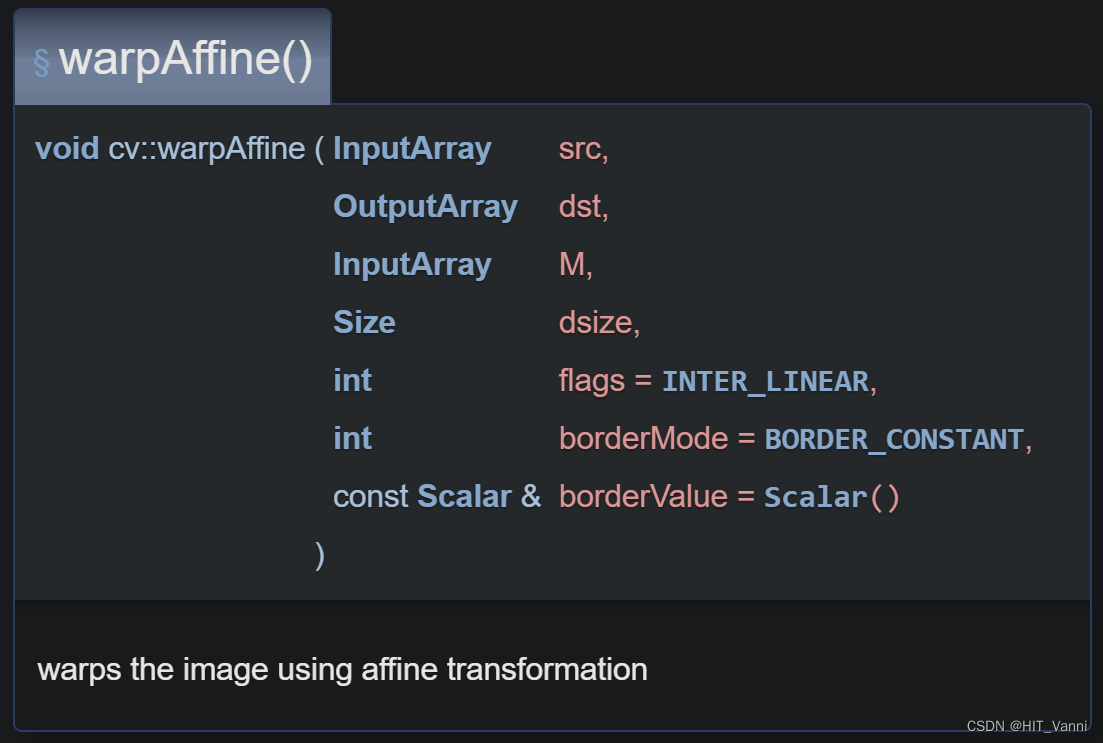
def warpAffine(src, M, dsize, dst=None, flags=None, borderMode=None, borderValue=None)
src:输入图像
M:运算矩阵,2行3列的,数据类型要求是float32位及以上
dsize:运算后矩阵的大小,也就是输出图片的尺寸
dst:输出图像
flags:插值方法的组合,与resize函数中的插值一样,可以查看cv2.resize
borderMode:像素外推方法,详情参考官网
borderValue:在恒定边框的情况下使用的borderValue值;默认情况下,它是 0
至此,完成了对图像部分数据处理。
2. 点云数据处理
2.1 从image_info中加载点云数据
这里的毫米波雷达点云数据在convert_Nuscenes.py中已经转换到了相机坐标系下
getitem()函数,\CenterFusion\src\lib\dataset\generic_dataset.py文件的131行
#  加载点云数据
if opt.pointcloud:
  pc_2d, pc_N, pc_dep, pc_3d = self._load_pc_data(img, img_info,
    trans_input, trans_output, flipped)  #  加载点云数据
  ret.update({ 'pc_2d': pc_2d,
               'pc_3d': pc_3d,
               'pc_N': pc_N,
               'pc_dep': pc_dep })   # 将点云数据添加到输出字典
首先对点与数据进行加载并处理,调用了_load_pc_data()函数,该函数在\CenterFusion\src\lib\dataset\generic_dataset.py文件的376行
  def _load_pc_data(self, img, img_info, inp_trans, out_trans, flipped=0):
    #点云原始特征一共有18维
    #x y z dyn_prop id rcs vx vy vx_comp vy_comp is_quality_valid ambig_state x_rms y_rms invalid_state pdh0 vx_rms vy_rms
    #这里在加载点云数据的时候已经转换到了相机坐标系下,所以此时的第三维是深度信息,xy分别是相机坐标系下的坐标
    img_height, img_width = img.shape[0], img.shape[1]
    radar_pc = np.array(img_info.get('radar_pc', None)) # 加载点云数据
    if radar_pc is None:
      return None, None, None, None

    # 计算到该点的距离
    depth = radar_pc[2,:]

    # 按距离过滤点云
    if self.opt.max_pc_dist > 0:                  # 过滤点云中距离过近的点
      mask = (depth <= self.opt.max_pc_dist)      # opt.max_pc_dist默认值为100.0m
      radar_pc = radar_pc[:,mask]
      depth = depth[mask]

    # 对毫米波雷达点云增加z方向偏置
    # train.sh中设置opt.pc_z_offset为0,故没有执行这一步
    if self.opt.pc_z_offset != 0:
      radar_pc[1,:] -= self.opt.pc_z_offset

    # 映射指向图像并过滤外部的图像
    pc_2d, mask = map_pointcloud_to_image(radar_pc, np.array(img_info['camera_intrinsic']),
                              img_shape=(img_info['width'],img_info['height']))
    '''
    这里主要注释一下,因为论文作者在进行数据转换的时候(convert_Nuscenes.py)就已经将雷达点转换到向相机坐标系中
    所以在这里只是需要把相机坐标系根据相机的内参转换到图像坐标系就可以了
    同时再转换过后有可能有的点不在图像范围内上述函数也将这些点给去掉了
    '''
    pc_3d = radar_pc[:,mask]

    # 按距离对点云进行排序
    ind = np.argsort(pc_2d[2,:])
    pc_2d = pc_2d[:,ind]
    pc_3d = pc_3d[:,ind]

    # 当图像进行翻转操作时对点云也进行翻转操作
    if flipped:
      pc_2d = self._flip_pc(pc_2d,  img_width)
      pc_3d[0,:] *= -1  # flipping the x dimension
      pc_3d[8,:] *= -1  # flipping x velocity (x is right, z is front)

    pc_2d, pc_3d, pc_dep = self._process_pc(pc_2d, pc_3d, img, inp_trans, out_trans, img_info)
    pc_N = np.array(pc_2d.shape[1])
        # pad point clouds with zero to avoid size mismatch error in dataloader
    n_points = min(self.opt.max_pc, pc_2d.shape[1])
    pc_z = np.zeros((pc_2d.shape[0], self.opt.max_pc))
    pc_z[:, :n_points] = pc_2d[:, :n_points]
    pc_3dz = np.zeros((pc_3d.shape[0], self.opt.max_pc))
    pc_3dz[:, :n_points] = pc_3d[:, :n_points]
        '''
        这里是为了防止在输入的时候尺度不一致导致出现问题,所以在这里将所有雷达点的个数都变成1000,
        前N个都是雷达点本身的特征,后边都是用0补齐的
        '''
    return pc_z, pc_N, pc_dep, pc_3dz
2.2 将点云都投影到仿射变换后的图像坐标系,同时对图像外的点进行过滤
_load_pc_data()中调用了_process_pc()函数,该函数在\CenterFusion\src\lib\dataset\generic_dataset.py文件的425行
def _process_pc(self, pc_2d, pc_3d, img, inp_trans, out_trans, img_info):
    img_height, img_width = img.shape[0], img.shape[1]

    # transform points
    mask = None
    if len(self.opt.pc_feat_lvl) > 0:
      pc_feat, mask = self._transform_pc(pc_2d, out_trans, self.opt.output_w, self.opt.output_h)
      '''
      这里由于作者论文中是将雷达处理后的到的特征与图像中用于回归的特则进行拼接,
      所以这里的数据转换就是对投影到图像上的雷达点转换到输出特征维度上,
      生成与图像特征相同大小的雷达特征
      同时将转换后的雷达点不在特征宽高内的点进行过滤
      '''
      pc_hm_feat = np.zeros((len(self.opt.pc_feat_lvl), self.opt.output_h, self.opt.output_w), np.float32)
      #用于保存生成的雷达特征
    if mask is not None:
      pc_N = np.array(sum(mask))
      pc_2d = pc_2d[:,mask]
      pc_3d = pc_3d[:,mask]
    else:
      pc_N = pc_2d.shape[1]

    # create point cloud pillars
    if self.opt.pc_roi_method == "pillars":
      pillar_wh = self.create_pc_pillars(img, img_info, pc_2d, pc_3d, inp_trans, out_trans)
    # generate point cloud channels
    for i in range(pc_N-1, -1, -1):
      for feat in self.opt.pc_feat_lvl:
        point = pc_feat[:,i]
        depth = point[2]
        ct = np.array([point[0], point[1]])
        ct_int = ct.astype(np.int32)

        if self.opt.pc_roi_method == "pillars":
          wh = pillar_wh[:,i]
          b = [max(ct[1]-wh[1], 0),
              ct[1],
              max(ct[0]-wh[0]/2, 0),
              min(ct[0]+wh[0]/2, self.opt.output_w)]
          b = np.round(b).astype(np.int32)

        elif self.opt.pc_roi_method == "hm":
          radius = (1.0 / depth) * self.opt.r_a + self.opt.r_b
          radius = gaussian_radius((radius, radius))
          radius = max(0, int(radius))
          x, y = ct_int[0], ct_int[1]
          height, width = pc_hm_feat.shape[1:3]
          left, right = min(x, radius), min(width - x, radius + 1)
          top, bottom = min(y, radius), min(height - y, radius + 1)
          b = np.array([y - top, y + bottom, x - left, x + right])
          b = np.round(b).astype(np.int32)

        if feat == 'pc_dep':
          channel = self.opt.pc_feat_channels['pc_dep']
          pc_hm_feat[channel, b[0]:b[1], b[2]:b[3]] = depth

        if feat == 'pc_vx':
          vx = pc_3d[8,i]
          channel = self.opt.pc_feat_channels['pc_vx']
          pc_hm_feat[channel, b[0]:b[1], b[2]:b[3]] = vx

        if feat == 'pc_vz':
          vz = pc_3d[9,i]
          channel = self.opt.pc_feat_channels['pc_vz']
          pc_hm_feat[channel, b[0]:b[1], b[2]:b[3]] = vz
        '''
        这里用于生成特征,特征的维度是3*112*200的,其中3个通道使用的雷达特征分别为pc_dep,pc_vx,pc_vz
        同时将框对应的位置在每个通道上用对应的属性进行赋值得到pc_hm_feat
        '''
    return pc_2d, pc_3d, pc_hm_feat
_process_pc()中调用了_transform_pc()函数,该函数在\CenterFusion\src\lib\dataset\generic_dataset.py文件的605行。
这里对点云的数据转换就是对投影到图像上的雷达点转换到经过仿射变换的输出特征维度上,同时删除图像范围以外的毫米波雷达点
def _transform_pc(self, pc_2d, trans, img_width, img_height, filter_out=True):

  if pc_2d.shape[1] == 0:
    return pc_2d, []

  pc_t = np.expand_dims(pc_2d[:2,:].T, 0)   # [3,N] -> [1,N,2]
  t_points = cv2.transform(pc_t, trans)     # 传入旋转矩阵及原始点位坐标,得到与变换后图片对应的点坐标点
  t_points = np.squeeze(t_points,0).T       # [1,N,2] -> [2,N]

  # 删除图像范围以外的毫米波雷达点
  if filter_out:
    mask = (t_points[0,:]<img_width) \
            & (t_points[1,:]<img_height) \
            & (0<t_points[0,:]) \
            & (0<t_points[1,:])
    out = np.concatenate((t_points[:,mask], pc_2d[2:,mask]), axis=0)
  else:
    mask = None
    out = np.concatenate((t_points, pc_2d[2:,:]), axis=0)

  return out, mask
2.3 生成柱状体,同时将柱状体投影到仿射变换后的图像坐标系
_process_pc()中调用了create_pc_pillars()函数,该函数在\CenterFusion\src\lib\dataset\generic_dataset.py文件的489行,create_pc_pillars用于生成论文中的柱状体
def create_pc_pillars(self, img, img_info, pc_2d, pc_3d, inp_trans, out_trans):
    pillar_wh = np.zeros((2, pc_3d.shape[1]))
    boxes_2d = np.zeros((0,8,2))
    pillar_dim = self.opt.pillar_dims                 #保存柱状图形的长宽高 0 1 2分别表示h,w,l
    v = np.dot(np.eye(3), np.array([1,0,0]))
    ry = -np.arctan2(v[2], v[0])

    for i, center in enumerate(pc_3d[:3,:].T):
      # Create a 3D pillar at pc location for the full-size image
      box_3d = compute_box_3d(dim=pillar_dim, location=center, rotation_y=ry)
      '''
      为每个雷达点生成柱状体
      1、首先计算物体的在照相机坐标系下,物体的全局方向角,用于表示物体的前进方向
      (我感觉这里是想每个生成的柱状体根据这个角度进行旋转,但是貌似作者这里根据角度生成的是一个单位阵,并没有发生变化)
      2、根据该方位角生成一个三维的旋转矩阵
      3、根据柱状体每个维度上的长度分别生成xyz三个坐标的8个点,这里为每个点生成的柱状体都是一样的
      4、将生成的柱状体移动到雷达点上,生成柱状体的坐标与雷达的坐标相加
      通过上述过程得到了每个雷达点柱状体
      '''
      box_2d = project_to_image(box_3d, img_info['calib']).T  # [2x8]
      '''
      由于生成柱状体的过程都是基于雷达三位点生成的也就是摄像机的坐标系下不是图像的坐标系,同时生成的是3d柱状体
      所以这里将3d柱状体投影到图像坐标系下,以上述雷达投影方式相同
      由于3d的柱状体是8个点所以投影下来就是2*8大小的矩阵
      '''
      ## save the box for debug plots
      if self.opt.debug:
        box_2d_img, m = self._transform_pc(box_2d, inp_trans, self.opt.input_w,
                                            self.opt.input_h, filter_out=False)
        boxes_2d = np.concatenate((boxes_2d, np.expand_dims(box_2d_img.T,0)),0)

      # transform points
      box_2d_t, m = self._transform_pc(box_2d, out_trans, self.opt.output_w, self.opt.output_h)
      #将生成的柱状体转换和图像特征相同的维度
      if box_2d_t.shape[1] <= 1:
        continue

      # get the bounding box in [xyxy] format
      bbox = [np.min(box_2d_t[0,:]),
              np.min(box_2d_t[1,:]),
              np.max(box_2d_t[0,:]),
              np.max(box_2d_t[1,:])] # format: xyxy
         #这里由于投影下来是8个点,但是对于2d来说只需要四个点就够了,所以就去了最外围的点围成的最大的框来表示柱状体的投影特征
      # store height and width of the 2D box
      pillar_wh[0,i] = bbox[2] - bbox[0]
      pillar_wh[1,i] = bbox[3] - bbox[1]
    #这里删除作者DEBUG的部分 在进行模型训练或测试的时候加上–debug 4就可以显示所有的结果图
    return pillar_wh
2.4 根据柱状体生成雷达特征
该步在_process_pc函数中,该步骤在\CenterFusion\src\lib\dataset\generic_dataset.py文件的445行
特征的维度是3112200的,其中3个通道使用的雷达特征分别为pc_dep,pc_vx,pc_vz
    # generate point cloud channels
    for i in range(pc_N-1, -1, -1):
      for feat in self.opt.pc_feat_lvl:
        point = pc_feat[:,i]
        depth = point[2]
        ct = np.array([point[0], point[1]])
        ct_int = ct.astype(np.int32)

        if self.opt.pc_roi_method == "pillars":
          wh = pillar_wh[:,i]
          b = [max(ct[1]-wh[1], 0),
              ct[1],
              max(ct[0]-wh[0]/2, 0),
              min(ct[0]+wh[0]/2, self.opt.output_w)]
          b = np.round(b).astype(np.int32)

        elif self.opt.pc_roi_method == "hm":
          radius = (1.0 / depth) * self.opt.r_a + self.opt.r_b
          radius = gaussian_radius((radius, radius))
          radius = max(0, int(radius))
          x, y = ct_int[0], ct_int[1]
          height, width = pc_hm_feat.shape[1:3]
          left, right = min(x, radius), min(width - x, radius + 1)
          top, bottom = min(y, radius), min(height - y, radius + 1)
          b = np.array([y - top, y + bottom, x - left, x + right])
          b = np.round(b).astype(np.int32)

        if feat == 'pc_dep':
          channel = self.opt.pc_feat_channels['pc_dep']
          pc_hm_feat[channel, b[0]:b[1], b[2]:b[3]] = depth

        if feat == 'pc_vx':
          vx = pc_3d[8,i]
          channel = self.opt.pc_feat_channels['pc_vx']
          pc_hm_feat[channel, b[0]:b[1], b[2]:b[3]] = vx

        if feat == 'pc_vz':
          vz = pc_3d[9,i]
          channel = self.opt.pc_feat_channels['pc_vz']
          pc_hm_feat[channel, b[0]:b[1], b[2]:b[3]] = vz
        '''
        这里用于生成特征,特征的维度是3*112*200的,其中3个通道使用的雷达特征分别为pc_dep,pc_vx,pc_vz
        同时将框对应的位置在每个通道上用对应的属性进行赋值得到pc_hm_feat
        '''
    return pc_2d, pc_3d, pc_hm_feat
到这里完成了点云数据的处理。
3. anns标注数据的处理
getitem()函数,\CenterFusion\src\lib\dataset\generic_dataset.py文件的139行
    pre_cts, track_ids = None, None
    # 对于tracking模式,加载前一帧图像和标注信息
    if opt.tracking:
      pre_image, pre_anns, frame_dist, pre_img_info = self._load_pre_data(
        img_info['video_id'], img_info['frame_id'],
        img_info['sensor_id'] if 'sensor_id' in img_info else 1)  # 加载前一帧图像和标注数据
      # 图像有翻转的情况
      if flipped:
        pre_image = pre_image[:, ::-1, :].copy()
        pre_anns = self._flip_anns(pre_anns, width)
        if pc_2d is not None:
          pc_2d = self._flip_pc(pc_2d,  width)
      if opt.same_aug_pre and frame_dist != 0:
        # 获取仿射变换矩阵
        trans_input_pre = trans_input
        trans_output_pre = trans_output
      else:
        c_pre, aug_s_pre, _ = self._get_aug_param(
          c, s, width, height, disturb=True)  # 获取前一帧图像的中心点、尺度和旋转角度的增强参数
        s_pre = s * aug_s_pre   # 更新前一帧图像的尺度
        trans_input_pre = get_affine_transform(
          c_pre, s_pre, rot, [opt.input_w, opt.input_h])   # 获取前一帧图像的输入仿射变换矩阵
        trans_output_pre = get_affine_transform(
          c_pre, s_pre, rot, [opt.output_w, opt.output_h])   # 获取前一帧图像的输出仿射变换矩阵
      pre_img = self._get_input(pre_image, trans_input_pre)  # 获取前一帧图像的输入图像
      pre_hm, pre_cts, track_ids = self._get_pre_dets(
        pre_anns, trans_input_pre, trans_output_pre)  # 获取前一帧图像的热力图和中心点
      ret['pre_img'] = pre_img  # 将前一帧图像的输入图像添加到输出字典
      if opt.pre_hm:
        ret['pre_hm'] = pre_hm  # 将前一帧图像的热力图添加到输出字典
      if opt.pointcloud:
        pre_pc_2d, pre_pc_N, pre_pc_hm, pre_pc_3d = self._load_pc_data(pre_img, pre_img_info,
            trans_input_pre, trans_output_pre, flipped)  # 加载前一帧图像的点云数据
        ret['pre_pc_2d'] = pre_pc_2d
        ret['pre_pc_3d'] = pre_pc_3d
        ret['pre_pc_N'] = pre_pc_N
        ret['pre_pc_hm'] = pre_pc_hm  # 将前一帧图像的点云数据添加到输出字典
    '''
    这部分针对追踪做的,目前还没做这个
    '''
    ### init samples  初始化样本
    self._init_ret(ret, gt_det)  # 初始化输出字典和ground truth检测信息
    '''
    初始化一些运行网络需要的东西,一方面用于网络的输入,另一方面用于计算损失
    输入的ret中包含的数据为:
    image:仿射变换后的图像     3*448*800
    pc_2d:投影到图像后的雷达点 3*1000(3表示xyz三个方向的特征)
    pc_3d:原始的雷达特征       18*1000(18表示原始的雷达特征)
    pc_N:1000点中有效雷达点的数量
    pc_dep:根据柱状体生成的雷达特征图3*112*200
    输出后增加的雷达特征:
    hm:        在对应类别通道赋值bbox中心点的高斯特征图         10*112*200
    ind: ct[1]*w+ct[0]                    128
    表示把特征变成一维向量后该类别对应的索引
    比如此时的点的坐标是(2,3),w,h分别是3,4;那么ind表示3*3+2
    cat:bbox的类别                  128
    mask:1表示该位置有框            128
    pc_hm:雷达特征                  3*112*200
    该特征是由pc_dep转换生成的,根据视锥体模型来获取到最相关的雷达点,将该雷达点的特征值赋值给对应的bbox来生成pc_hm
    reg:最后预测的为整数,该部分用于保存根据hw计算出来的bbox中心点小数偏置       128*2
    比如:bbox中心点为(22.4,45.6),保存的为(0.4,0.6)
    reg_mask: 表示对应位置有值         128*2
    wh:bbox对应的wh                   128*2
    wh_mask:这个位置有wh              128*2
    nuscenes_att:表示物体的状态       128*8
    一共定义了物体的8种状态,把bbox的对应状态赋值为1
    nuscenes_att_mask:表示该位置有值      128*8
    velocity:box 在相机坐标系中的速度     128*3
    velocity_mask:表示该位置有值          128*3
    dep:Z值*aug_s            128*1
    dep_mask:有无z           128*1
    dim:bbox的lhw            128*3
    dim_mask:有数值          128*3
    amodel_offset:保存根据实际中心点bbox中心点小数偏置   128*2
    amodel_offset_mask:有值   128*2
    rosbin:a小于pi/6或者大于5pi/6第一个位置为0,-pi/6到-5pi/6第二个位置为0      128*2
    rosres:a大于-pi/6或者小于-5pi/6第一个位置为a-(-0.5*pi),-pi/6到-5pi/6第二个位置为a-(0.5*np.pi)      128*2
    ros_mask:表示物体是否旋转             128

    其中用于网络输入的部分为:
    image:应用仿射变换后的图像 3*448*800
    pc_dep:根据柱状体生成的雷达特征图,在进行Secondary Regression Heads用于和图像特征进行拼接
    计算损失的部分:

    '''
    calib = self._get_calib(img_info, width, height)  # 获取标定信息

    # get velocity transformation matrix  获取速度变换矩阵
    if "velocity_trans_matrix" in img_info:
      velocity_mat = np.array(img_info['velocity_trans_matrix'], dtype=np.float32)
    else:
      velocity_mat = np.eye(4)

    num_objs = min(len(anns), self.max_objs)  # 获取目标数量
    for k in range(num_objs):
      ann = anns[k]   # 获取第k个物体标注
      cls_id = int(self.cat_ids[ann['category_id']])  # 获取物体类别ID
      if cls_id > self.opt.num_classes or cls_id <= -999:  # 如果物体类别ID超出了类别数量或为-999,则忽略
        continue
      bbox, bbox_amodal = self._get_bbox_output(
        ann['bbox'], trans_output, height, width)  # 获取边框和遮挡边框
      '''
      ann['bbox']中保存的box的是xyhw,xy表示bbox的左上角坐标
      该函数首先将xyhw转换成xyxy
      之后将bbox框应用和图像一样的仿射变换映射输出维度大小
      最后将bbox限定在图像内,图像外的部分以图象的边缘赋值
      '''
      if cls_id <= 0 or ('iscrowd' in ann and ann['iscrowd'] > 0):   # 如果物体类别ID小于等于0或注释中标记为iscrowd,则忽略
        self._mask_ignore_or_crowd(ret, cls_id, bbox)
        continue
      self._add_instance(
        ret, gt_det, k, cls_id, bbox, bbox_amodal, ann, trans_output, aug_s,
        calib, pre_cts, track_ids)
   if self.opt.debug > 0 or self.enable_meta: # 判断debug是否开启或meta是否启用
     # 对ground truth目标框的格式进行处理
     gt_det = self._format_gt_det(gt_det)
     # 设置信息
     meta = {'c': c, 's': s, 'gt_det': gt_det, 'img_id': img_info['id'],
             'img_path': img_path, 'calib': calib,
             'img_width': img_info['width'], 'img_height': img_info['height'],
             'flipped': flipped, 'velocity_mat':velocity_mat}
     # 将元信息添加到返回的字典中
     ret['meta'] = meta
   # 设置返回的字典项calib
   ret['calib'] = calib
   return ret
getitem()中调用了_add_instance()函数,该函数在\CenterFusion\src\lib\dataset\generic_dataset.py文件的745行
  def _add_instance(
    self, ret, gt_det, k, cls_id, bbox, bbox_amodal, ann, trans_output,
    aug_s, calib, pre_cts=None, track_ids=None):
    h, w = bbox[3] - bbox[1], bbox[2] - bbox[0]
    if h <= 0 or w <= 0:
      return
    radius = gaussian_radius((math.ceil(h), math.ceil(w)))
    '''
    计算高斯圆半径,分为三种情况,自行查看下面参考文献
    参考:https://zhuanlan.zhihu.com/p/452632600
    1、预测框与gt box的两个角点是以r半径的圆外切,gt小于pred
    2、预测的框和GTbox两个角点以r为半径的圆内切,gt大于pred
    3、预测的框和GTbox两个角点以r为半径的圆一个边内切,一个边外切
    考虑真实的框在预测框的内部
    iou=H*W/((H+2R)*(W+2R))从而计算出来R
    最后取上述三钟情况r算出来的最小值
    '''
    radius = max(0, int(radius))
    ct = np.array(
      [(bbox[0] + bbox[2]) / 2, (bbox[1] + bbox[3]) / 2], dtype=np.float32)
    ct_int = ct.astype(np.int32)
    ret['cat'][k] = cls_id - 1
    ret['mask'][k] = 1
    if 'wh' in ret:
      ret['wh'][k] = 1. * w, 1. * h
      ret['wh_mask'][k] = 1
    ret['ind'][k] = ct_int[1] * self.opt.output_w + ct_int[0]
    ret['reg'][k] = ct - ct_int
    ret['reg_mask'][k] = 1
    draw_umich_gaussian(ret['hm'][cls_id - 1], ct_int, radius)

    gt_det['bboxes'].append(
      np.array([ct[0] - w / 2, ct[1] - h / 2,
                ct[0] + w / 2, ct[1] + h / 2], dtype=np.float32))
    gt_det['scores'].append(1)
    gt_det['clses'].append(cls_id - 1)
    gt_det['cts'].append(ct)

    if 'tracking' in self.opt.heads:
      if ann['track_id'] in track_ids:
        pre_ct = pre_cts[track_ids.index(ann['track_id'])]
        ret['tracking_mask'][k] = 1
        ret['tracking'][k] = pre_ct - ct_int
        gt_det['tracking'].append(ret['tracking'][k])
      else:
        gt_det['tracking'].append(np.zeros(2, np.float32))

    if 'ltrb' in self.opt.heads:
      ret['ltrb'][k] = bbox[0] - ct_int[0], bbox[1] - ct_int[1], \
        bbox[2] - ct_int[0], bbox[3] - ct_int[1]
      ret['ltrb_mask'][k] = 1

    ## ltrb_amodal is to use the left, top, right, bottom bounding box representation
    # to enable detecting out-of-image bounding box (important for MOT datasets)
    if 'ltrb_amodal' in self.opt.heads:
      ret['ltrb_amodal'][k] = \
        bbox_amodal[0] - ct_int[0], bbox_amodal[1] - ct_int[1], \
        bbox_amodal[2] - ct_int[0], bbox_amodal[3] - ct_int[1]
      ret['ltrb_amodal_mask'][k] = 1
      gt_det['ltrb_amodal'].append(bbox_amodal)

    if 'nuscenes_att' in self.opt.heads:
      if ('attributes' in ann) and ann['attributes'] > 0:
        att = int(ann['attributes'] - 1)
        ret['nuscenes_att'][k][att] = 1
        ret['nuscenes_att_mask'][k][self.nuscenes_att_range[att]] = 1
      gt_det['nuscenes_att'].append(ret['nuscenes_att'][k])

    if 'velocity' in self.opt.heads:
      if ('velocity_cam' in ann) and min(ann['velocity_cam']) > -1000:
        ret['velocity'][k] = np.array(ann['velocity_cam'], np.float32)[:3]
        ret['velocity_mask'][k] = 1
      gt_det['velocity'].append(ret['velocity'][k])

    if 'hps' in self.opt.heads:
      self._add_hps(ret, k, ann, gt_det, trans_output, ct_int, bbox, h, w)

    if 'rot' in self.opt.heads:
      self._add_rot(ret, ann, k, gt_det)

    if 'dep' in self.opt.heads:
      if 'depth' in ann:
        ret['dep_mask'][k] = 1
        ret['dep'][k] = ann['depth'] * aug_s
        gt_det['dep'].append(ret['dep'][k])
      else:
        gt_det['dep'].append(2)

    if 'dim' in self.opt.heads:
      if 'dim' in ann:
        ret['dim_mask'][k] = 1
        ret['dim'][k] = ann['dim']
        gt_det['dim'].append(ret['dim'][k])
      else:
        gt_det['dim'].append([1,1,1])

    if 'amodel_offset' in self.opt.heads:
      if 'amodel_center' in ann:
        amodel_center = affine_transform(ann['amodel_center'], trans_output)
        ret['amodel_offset_mask'][k] = 1
        ret['amodel_offset'][k] = amodel_center - ct_int
        gt_det['amodel_offset'].append(ret['amodel_offset'][k])
      else:
        gt_det['amodel_offset'].append([0, 0])

    if self.opt.pointcloud:
      ## get pointcloud heatmap
      if self.opt.disable_frustum:
      '''
      对于训练阶段上述是False,测试的时候为True
      由于不知道实际的bbox所以之类直接使用上述生成的雷达特征
      '''
        ret['pc_hm'] = ret['pc_dep']
        if opt.normalize_depth:
          ret['pc_hm'][self.opt.pc_feat_channels['pc_dep']] /= opt.max_pc_dist
      else:
        dist_thresh = get_dist_thresh(calib, ct, ann['dim'], ann['alpha'])
        '''
        首先根据ann['dim']中的lwh生成一个3d的box(用8个点的三维坐标来表示)
        之后根据alpha来计算出全局观测角,之后对上述生成的3dbox进行旋转,来获得真实框的坐标
        最后通过计算8个坐标中z方向的最大值和最小值,利用而这插值的重点来作为阈值(用于之后的视锥体中雷达点的过滤)
        '''
        pc_dep_to_hm(ret['pc_hm'], ret['pc_dep'], ann['depth'], bbox, dist_thresh, self.opt)
_add_instance()中的最后调用了pc_dep_to_hm()函数,该函数在\CenterFusion\src\lib\utils\pointcloud.py文件的338行
在训练过程中,利用视锥体来过滤不需要的雷达点,同时将最小距离的雷达点当作是与物体最相关的来作为最后的雷达特征
def pc_dep_to_hm(pc_hm, pc_dep, dep, bbox, dist_thresh, opt):
    if isinstance(dep, list) and len(dep) > 0:
      dep = dep[0]
    ct = np.array(
      [(bbox[0] + bbox[2]) / 2, (bbox[1] + bbox[3]) / 2], dtype=np.float32)
    bbox_int = np.array([np.floor(bbox[0]),
                         np.floor(bbox[1]),
                         np.ceil(bbox[2]),
                         np.ceil(bbox[3])], np.int32)# format: xyxy

    roi = pc_dep[:, bbox_int[1]:bbox_int[3]+1, bbox_int[0]:bbox_int[2]+1]
    pc_dep = roi[opt.pc_feat_channels['pc_dep']]
    pc_vx = roi[opt.pc_feat_channels['pc_vx']]
    pc_vz = roi[opt.pc_feat_channels['pc_vz']]

    nonzero_inds = np.nonzero(pc_dep)  #返回数组a中非零元素的索引值数组,该部分表示返回含有雷达特征的矩阵坐标信息

    if len(nonzero_inds[0]) > 0:
    #   nonzero_pc_dep = np.exp(-pc_dep[nonzero_inds])
      nonzero_pc_dep = pc_dep[nonzero_inds]
      nonzero_pc_vx = pc_vx[nonzero_inds]
      nonzero_pc_vz = pc_vz[nonzero_inds]

      ## Get points within dist threshold
      within_thresh = (nonzero_pc_dep < dep+dist_thresh) \
              & (nonzero_pc_dep > max(0, dep-dist_thresh))

      pc_dep_match = nonzero_pc_dep[within_thresh]
      pc_vx_match = nonzero_pc_vx[within_thresh]
      pc_vz_match = nonzero_pc_vz[within_thresh]
          '''
          这里首先根据包含雷达点的坐标来获得所有雷达点的深度信息保存在nonzero_pc_dep中,
          之后根据上述得到的阈值将真实深度信息加减阈值以为的雷达点过滤掉,
          其中dep是anns['dep']表示该anns的深度信息,dis_thresh是上文中获取得到的框高度的一半(理性这么理解),
          通过这两个坐标可以得到框在z方向的两个阈值,将该范围外的点进行过滤,分别对depth,vx,vz这三个特征来进行过滤,
          上述过程就是作者提到的利用视锥体来过滤掉一些无关的雷达点,
          结合作者论文中给出的图,我是这么理解代码的,首先这里的深度信息是表示是物体到摄像机的距离,之后阈值的两端分别用的是
          dep-dis-dis_thresh和dep+dis_thresh,同时roi对应着图像中的Image Plane中的红色框,
          所以此时根据现有的深度信息和图像平面的举行就可以构建一个视锥体模型,来过滤点深度信息在视锥体之外的点
          '''
      if len(pc_dep_match) > 0:
        arg_min = np.argmin(pc_dep_match)
        dist = pc_dep_match[arg_min]
        vx = pc_vx_match[arg_min]
        vz = pc_vz_match[arg_min]
        if opt.normalize_depth:
          dist /= opt.max_pc_dist

        w = bbox[2] - bbox[0]
        w_interval = opt.hm_to_box_ratio*(w)
        w_min = int(ct[0] - w_interval/2.)
        w_max = int(ct[0] + w_interval/2.)

        h = bbox[3] - bbox[1]
        h_interval = opt.hm_to_box_ratio*(h)
        h_min = int(ct[1] - h_interval/2.)
        h_max = int(ct[1] + h_interval/2.)

        pc_hm[opt.pc_feat_channels['pc_dep'],
               h_min:h_max+1,
               w_min:w_max+1+1] = dist
        pc_hm[opt.pc_feat_channels['pc_vx'],
               h_min:h_max+1,
               w_min:w_max+1+1] = vx
        pc_hm[opt.pc_feat_channels['pc_vz'],
               h_min:h_max+1,
               w_min:w_max+1+1] = vz
        '''
        这里是找出论文中所说的和物体最对应的雷达的点,由于视锥体中有可能含有多个雷达点,作者取得是最近的雷达点,
        同时我感觉是由于雷达本身构造的特征不能太大,所以作者再利用bbox的时候设置类一个缩放因子,
        将原始的2d的bbox来进行缩放来得到最后的雷达区域,同时雷达区域的值是所有的雷达点中深度信息最小的那个点所对应的特征,
        最后分别对三个特征都进行上述的赋值过程来的到最后的输入雷达特征,
        上述过程针对的是作者所说的训练阶段,使用的用bbox来对雷达特征进行操作的。
        '''
继续分析分析__getitem__()函数,\CenterFusion\src\lib\dataset\generic_dataset.py文件的199行:
    if self.opt.debug > 0 or self.enable_meta: # 判断debug是否开启或meta是否启用
      # 对ground truth目标框的格式进行处理
      gt_det = self._format_gt_det(gt_det)
      # 设置信息
      meta = {'c': c, 's': s, 'gt_det': gt_det, 'img_id': img_info['id'],
              'img_path': img_path, 'calib': calib,
              'img_width': img_info['width'], 'img_height': img_info['height'],
              'flipped': flipped, 'velocity_mat':velocity_mat}
      # 将元信息添加到返回的字典中
      ret['meta'] = meta
    # 设置返回的字典项calib
    ret['calib'] = calib
    return ret
4. getitem(self, index)代码注释总结
def __getitem__(self, index):
    opt = self.opt # 获取参数配置
    img, anns, img_info, img_path = self._load_data(index) # 加载图像数据、标注数据、图像信息和图像路径
    height, width = img.shape[0], img.shape[1] # 获取图像高度和宽度
    ## sort annotations based on depth form far to near,按照深度从远到近对注释进行排序
    new_anns = sorted(anns, key=lambda k: k['depth'], reverse=True)
    ## Get center and scale from image,从图像中获取中心点和尺度
    c = np.array([img.shape[1] / 2., img.shape[0] / 2.], dtype=np.float32) # 中心点
    s = max(img.shape[0], img.shape[1]) * 1.0 if not self.opt.not_max_crop \
      else np.array([img.shape[1], img.shape[0]], np.float32) # 尺度,取图像较大的一边作为基准,如果未设置not_max_crop参数,尺度为图像宽高,否则按照not_max_crop的设置取尺度
    aug_s, rot, flipped = 1, 0, 0 # 数据增强参数,包括尺度、旋转和是否翻转
    ## data augmentation for training set,对于训练集进行数据增强
    if 'train' in self.split:
      c, aug_s, rot = self._get_aug_param(c, s, width, height) # 获取中心点、尺度和旋转角度的增强参数
      s = s * aug_s # 更新尺度
      if np.random.random() < opt.flip: # 随机翻转
        flipped = 1
        img = img[:, ::-1, :]
        anns = self._flip_anns(anns, width)
    trans_input = get_affine_transform(
      c, s, rot, [opt.input_w, opt.input_h]) # 获取输入图像的仿射变换矩阵
    trans_output = get_affine_transform(
      c, s, rot, [opt.output_w, opt.output_h]) # 获取输出图像的仿射变换矩阵
    inp = self._get_input(img, trans_input) # 获取输入图像
    ret = {'image': inp} # 初始化输出字典,包含输入图像
    gt_det = {'bboxes': [], 'scores': [], 'clses': [], 'cts': []} # 初始化ground truth检测信息,包含边框、得分、类别和中心点
    #  load point cloud data,加载点云数据
    if opt.pointcloud:
      pc_2d, pc_N, pc_dep, pc_3d = self._load_pc_data(img, img_info,
        trans_input, trans_output, flipped) # 加载点云数据
      ret.update({ 'pc_2d': pc_2d,
                   'pc_3d': pc_3d,
                   'pc_N': pc_N,
                   'pc_dep': pc_dep }) # 将点云数据添加到输出字典
    pre_cts, track_ids = None, None
    if opt.tracking:
      pre_image, pre_anns, frame_dist, pre_img_info = self._load_pre_data(
        img_info['video_id'], img_info['frame_id'],
        img_info['sensor_id'] if 'sensor_id' in img_info else 1) # 加载前一帧图像和标注数据
      if flipped:
        pre_image = pre_image[:, ::-1, :].copy()
        pre_anns = self._flip_anns(pre_anns, width)
        if pc_2d is not None:
          pc_2d = self._flip_pc(pc_2d,  width)
      if opt.same_aug_pre and frame_dist != 0:
        trans_input_pre = trans_input
        trans_output_pre = trans_output
      else:
        c_pre, aug_s_pre, _ = self._get_aug_param(
          c, s, width, height, disturb=True) # 获取前一帧图像的中心点、尺度和旋转角度的增强参数
        s_pre = s * aug_s_pre # 更新前一帧图像的尺度
        trans_input_pre = get_affine_transform(
          c_pre, s_pre, rot, [opt.input_w, opt.input_h]) # 获取前一帧图像的输入仿射变换矩阵
        trans_output_pre = get_affine_transform(
          c_pre, s_pre, rot, [opt.output_w, opt.output_h]) # 获取前一帧图像的输出仿射变换矩阵
      pre_img = self._get_input(pre_image, trans_input_pre) # 获取前一帧图像的输入图像
      pre_hm, pre_cts, track_ids = self._get_pre_dets(
        pre_anns, trans_input_pre, trans_output_pre) # 获取前一帧图像的热力图和中心点
      ret['pre_img'] = pre_img # 将前一帧图像的输入图像添加到输出字典
      if opt.pre_hm:
        ret['pre_hm'] = pre_hm # 将前一帧图像的热力图添加到输出字典
      if opt.pointcloud:
        pre_pc_2d, pre_pc_N, pre_pc_hm, pre_pc_3d = self._load_pc_data(pre_img, pre_img_info,
            trans_input_pre, trans_output_pre, flipped) # 加载前一帧图像的点云数据
        ret['pre_pc_2d'] = pre_pc_2d
        ret['pre_pc_3d'] = pre_pc_3d
        ret['pre_pc_N'] = pre_pc_N
        ret['pre_pc_hm'] = pre_pc_hm # 将前一帧图像的点云数据添加到输出字典
    ### init samples,初始化样本
    self._init_ret(ret, gt_det) # 初始化输出字典和ground truth检测信息
    calib = self._get_calib(img_info, width, height) # 获取标定信息
    # get velocity transformation matrix,获取速度变换矩阵
    if "velocity_trans_matrix" in img_info:
      velocity_mat = np.array(img_info['velocity_trans_matrix'], dtype=np.float32)
    else:
      velocity_mat = np.eye(4)

    num_objs = min(len(anns), self.max_objs) # 获取物体数量
    for k in range(num_objs):
      ann = anns[k] # 获取第k个物体标注
      cls_id = int(self.cat_ids[ann['category_id']]) # 获取物体类别ID
      if cls_id > self.opt.num_classes or cls_id <= -999: # 如果物体类别ID超出了类别数量或为-999,则忽略
        continue
      bbox, bbox_amodal = self._get_bbox_output(
        ann['bbox'], trans_output, height, width) # 获取边框和遮挡边框
      if cls_id <= 0 or ('iscrowd' in ann and ann['iscrowd'] > 0): # 如果物体类别ID小于等于0或注释中标记为iscrowd,则忽略
        self._mask_ignore_or_crowd(ret, cls_id, bbox)
        continue
      self._add_instance(
        ret, gt_det, k, cls_id, bbox, bbox_amodal, ann, trans_output, aug_s,
        calib, pre_cts, track_ids)
   if self.opt.debug > 0 or self.enable_meta: # 判断debug是否开启或meta是否启用
     # 对ground truth目标框的格式进行处理
     gt_det = self._format_gt_det(gt_det)
     # 设置信息
     meta = {'c': c, 's': s, 'gt_det': gt_det, 'img_id': img_info['id'],
             'img_path': img_path, 'calib': calib,
             'img_width': img_info['width'], 'img_height': img_info['height'],
             'flipped': flipped, 'velocity_mat':velocity_mat}
     # 将元信息添加到返回的字典中
     ret['meta'] = meta
   # 设置返回的字典项calib
   ret['calib'] = calib
   return ret
