基本情况
- 出处:Javanmardi M, Javanmardi E, Gu Y, et al. Towards high-definition 3D urban mapping: Road feature-based registration of mobile mapping systems and aerial imagery[J]. Remote Sensing, 2017, 9(10): 975.
- 原文地址:Remote Sensing | Free Full-Text | Towards High-Definition 3D Urban Mapping: Road Feature-Based Registration of Mobile Mapping Systems and Aerial Imagery
摘要
各种应用程序都使用移动测绘系统 (MMS) 作为主要的 3D 城市遥感平台。 然而,MMS获取的三维数据的准确度和精度高度依赖于车辆自定位的性能,这通常由高端全球导航卫星系统(GNSS)/惯性测量单元(IMU)执行 ) 一体化。 然而,GNSS/IMU 定位质量在高楼林立的密集城市地区显着下降,阻挡和反射卫星信号。 传统地标更新方法通过测量地面控制点 (GCP) 并手动识别数据中的这些点来提高 MMS 精度,这种方法既费力又耗时。 在本文中,我们提出了一个新颖而全面的框架,通过利用从高分辨率空中监视数据中提取的道路特征来自动对 MMS 数据进行地理配准。 所提出的框架包含三个关键步骤:
- (1) 从 MMS 和航拍数据中提取道路特征;
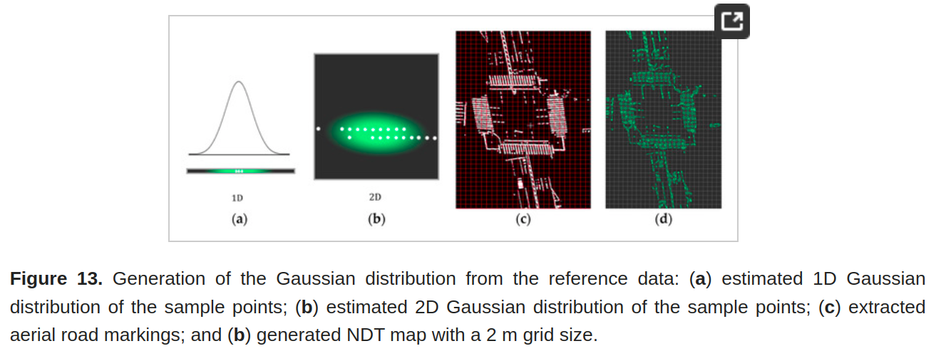
- (2) 从提取的空中道路特征中得到高斯混合模型;
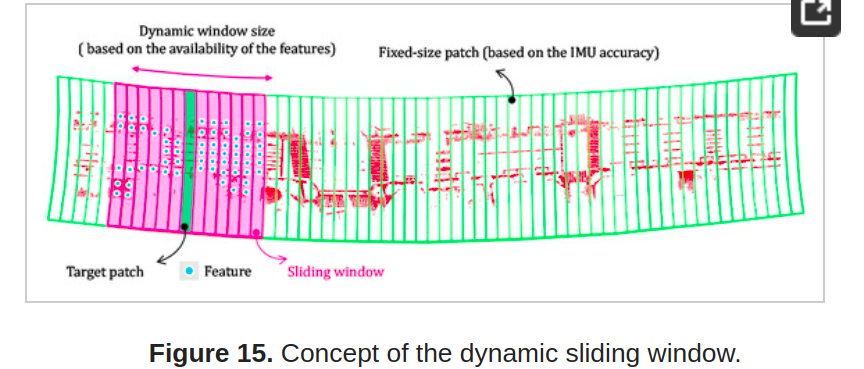
- (3) 使用动态滑动窗口和正态分布变换 (NDT) 将 MMS 数据配准到航空地图。 使用现场数据验证了所提出框架的准确性,证明它是高精度城市测绘的可靠解决方案。
图文
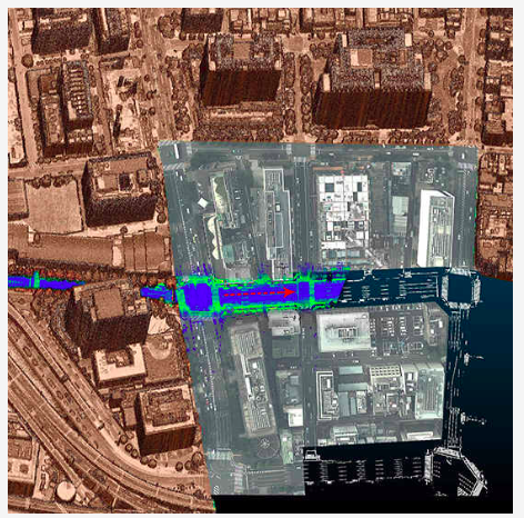
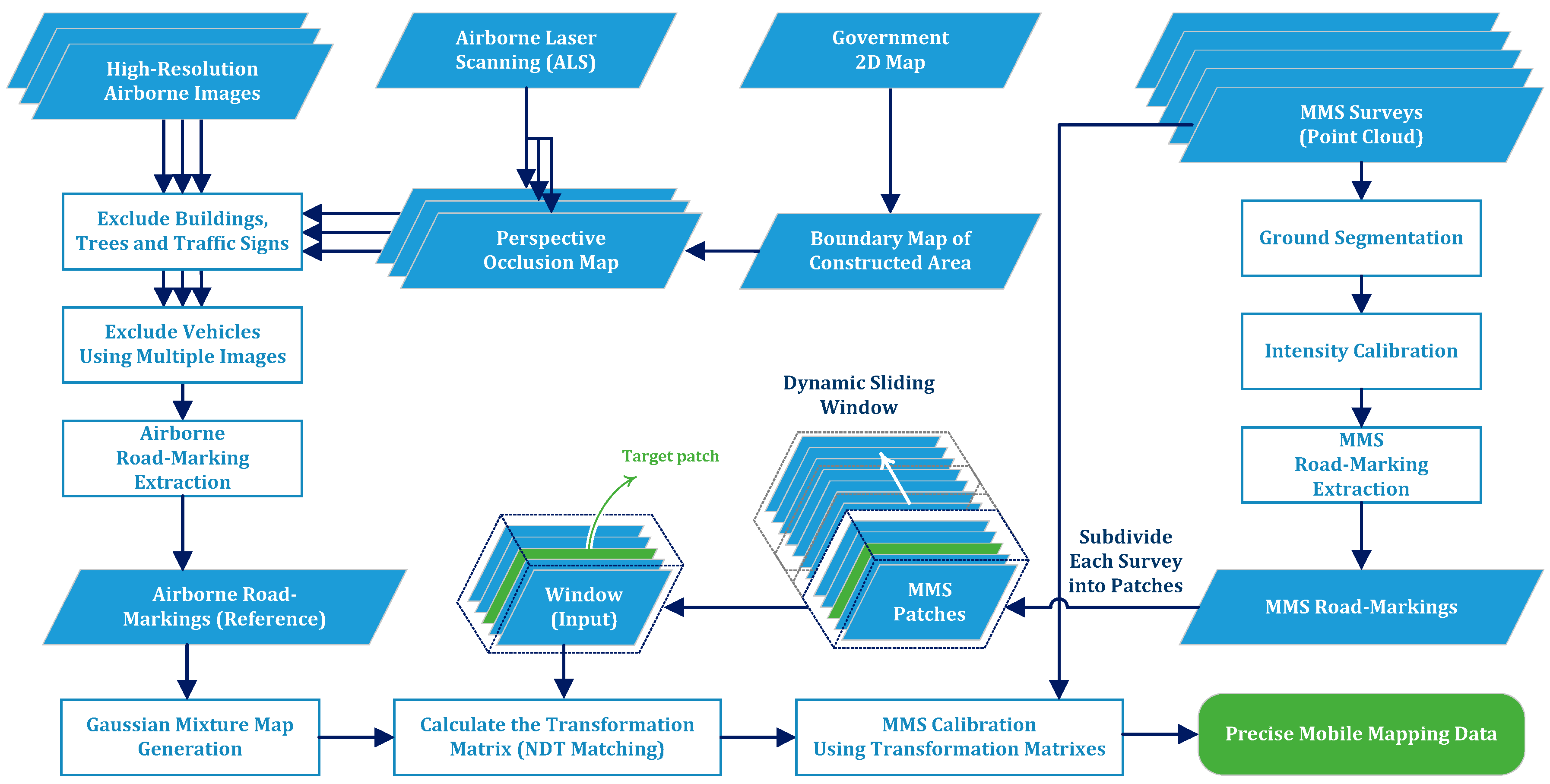
Figure 2. The overall workflow of the proposed framework.

Figure 3. Sample road markings in the aerial images of the Hitotsubashi area in central Tokyo. Some of the problematic areas are highlighted by the red dotted rectangles.

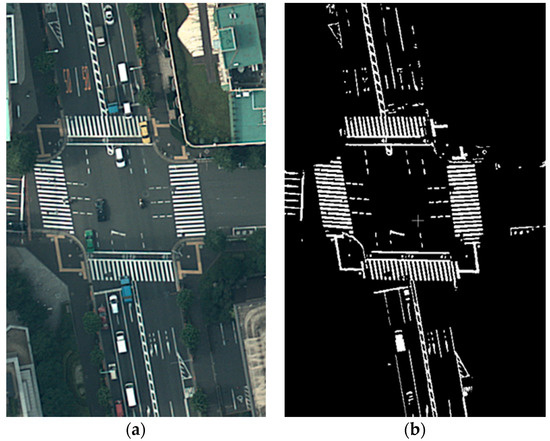
Figure 7. Road marking extraction from an aerial image by adaptive thresholding: (a) a part of the original aerial image; and (b) result of the road marking extraction process.
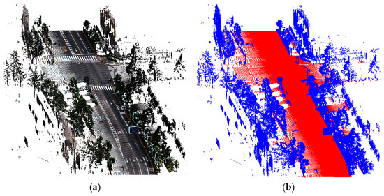
Figure 8. Road segmentation from an MMS point cloud: (a) original MMS point cloud consisting of buildings, trees, vehicles and road signs (RGB color is derived from the camera); and (b) the result of ground segmentation. The red points represent the ground, and the blue points are off-ground.
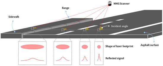
Figure 9. The effect of range and incidence angle on the shape of the laser footprint and the power of the reflected signal. As can be seen, as the range increase and the incidence angle decreases, area of the laser footprint increases, which degrades the quality of sampling.
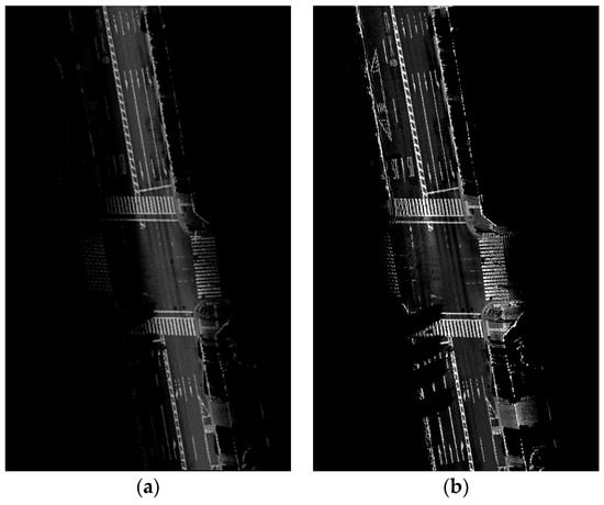
Figure 11. Intensity calibration of MMS point cloud: (a) original intensity of the MMS point cloud; and (b) calibrated intensity using the proposed method.

设备:


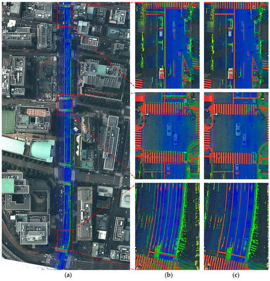
Figure 21. Visual evaluation of the proposed method for survey No. 6: (a) survey route of the MMS on the aerial image (after registration); (b) enlarged view of the original MMS point cloud before registration (the red points are aerial road markings); and (c) enlarged view of the MMS point cloud after applying the proposed method (the red points are aerial road markings).
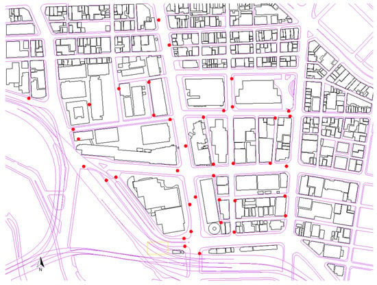
Figure 23. Distribution of the GCPs collected in the experimental area utilizing the total station survey. The GCPs are from the corner points of road signs, which are clearly captured by both the MMS camera and the point cloud.
