Packet Tracer - 配置和验证小型网络
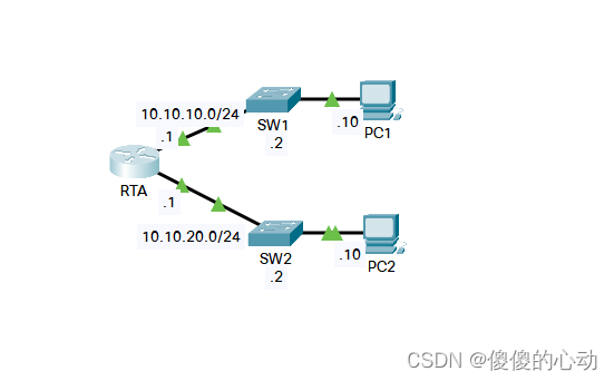
地址分配表
| 设备 | 接口 | IP 地址 | 子网掩码 | 默认网关 |
| RTA | G0/0 | 10.10.10.1 | 255.255.255.0 | 不适用 |
| G0/1 | 10.10.20.1 | 255.255.255.0 | 不适用 | |
| SW1 | VLAN1 | 10.10.10.2 | 255.255.255.0 | 10.10.10.1 |
| SW2 | VLAN1 | 10.10.20.2 | 255.255.255.0 | 10.10.20.1 |
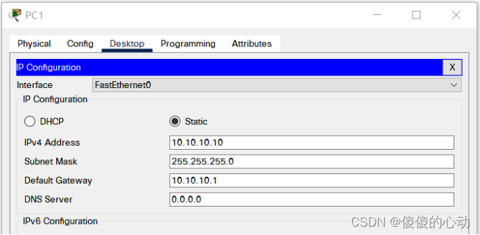
| PC1 | NIC | 10.10.10.10 | 255.255.255.0 | 10.10.10.1 |
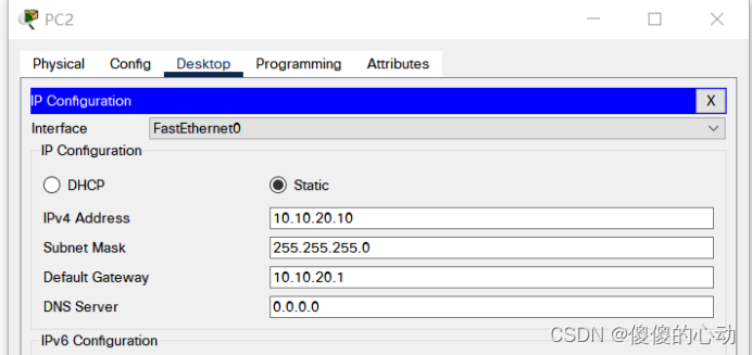
| PC2 | NIC | 10.10.20.10 | 255.255.255.0 | 10.10.20.1 |
目标
第 1 部分:配置设备并验证连接
第 2 部分:用 Show 命令收集信息
背景信息
在本活动中,您应使用基本设置(包括 IP 编址)配置 RTA。 您还应配置 SW1 进行远程管理并配置 PC。 成功验证连接后,您应使用 show 命令收集有关网络的信息。
注:用户 EXEC 密码是 cisco。 特权 EXEC 密码为 class。
拓扑图
第 1 部分: 配置设备并验证连接
步骤 1: 将基本配置应用于 RTA。
a. 使用以下信息和地址分配表,配置 RTA:
· 主机名和横幅
· 线路密码设置为 cisco;加密密码设置为 class
· LAN 接口的 IP 编址和描述
b. 保存配置。
步聚 2: 在 PC1 和 PC2 上配置编址。
a. 使用地址分配表,为 PC1 和 PC2 配置 IP 编址。
b. 测试 PC1 和 PC2 之间的连接。 根据情况进行故障排除。
步骤 3: 配置 SW1 以进行远程管理。
a. 使用地址分配表,配置 SW1 的管理接口。
b. 配置默认网关地址。
c. 保存配置。
第 2 部分: 用 Show 命令收集信息
步骤 1: 从 show interface 命令输出收集信息。
发出以下其中一个命令,然后回答相关问题:
show ip interface brief
show interfaces
show ip interface
哪个命令会显示端口状态?
show ip interface brief
show interfaces
show ip interface
哪个命令仅显示 IP 地址(无子网掩码或前缀)?
show ip interface brief
哪个命令会显示接口中配置的描述?
show interfaces
哪个命令会显示 IP 广播地址?
show interfaces
哪个命令会显示接口的 MAC 地址?
show interfaces
步骤 2: 从 show ip route 命令输出收集信息。
发出以下其中一个命令,然后回答相关问题:
show ip route
show ip route connected
根据 show ip route 命令的输出,路由器已知的网络数量有多少?
2_10.10.10.0/24&10.10.20.0/24
路由表的行开头的 L 表示什么?本地接口
路由表中列出的 /32 前缀表示什么?接口的主机地址
步骤 3: 在接口状态更改后,收集信息。
a. 在 RTA 中,关闭 Gigabit Ethernet 0/0 接口并发出 show ip route command. 现在路由表中显示的网络数量有多少?1_0.10.20.0/24
b. 尝试 ping PC1。 ping 是否成功?没有
c. 发出 show ip interface brief 命令。 Gigabit Ethernet 0/0 接口的状态是什么?在行政上下降(administratively down)
d. 重新激活 Gigabit Ethernet 0/0 接口。 发出 show ip route 命令。 路由表是否重新填充?是的
能从路由表中显示的路由接口状态推断出什么信息?
接口必须处于活动状态才能在路由表中列出。
实验步骤:
RTA:
Router>en

Router#conf t

Enter configuration commands, one per line. End with CNTL/Z.

Router(config)#hostname RTA

RTA(config)#banner motd #This is RTA router#

RTA(config)#line console 0

RTA(config-line)#password cisco

RTA(config-line)#login

RTA(config-line)#exit

RTA(config)#line vty 0 15

RTA(config-line)#password cisco

RTA(config-line)#login

RTA(config-line)#exit

RTA(config)#enable secret class

RTA(config)#int g0/0

RTA(config-if)#description G0/0

RTA(config-if)#ip add 10.10.10.1 255.255.255.0

RTA(config-if)#no shut

RTA(config)#int g0/1

RTA(config-if)#description G0/1

RTA(config-if)#ip add 10.10.20.1 255.255.255.0

RTA(config-if)#no shut
%LINK-5-CHANGED: Interface GigabitEthernet0/0, changed state to up
%LINEPROTO-5-UPDOWN: Line protocol on Interface GigabitEthernet0/0, changed state to up
RTA(config-if)#
%LINK-5-CHANGED: Interface GigabitEthernet0/1, changed state to up
%LINEPROTO-5-UPDOWN: Line protocol on Interface GigabitEthernet0/1, changed state to up
RTA(config-if)#exit
RTA(config)#end
RTA#
%SYS-5-CONFIG_I: Configured from console by console
RTA#wr

Building configuration...

[OK]

RTA#
SW1:
SW1(config)#interface vlan 1

SW1(config-if)#ip address 10.10.10.2 255.255.255.0

SW1(config-if)#no shu

SW1(config-if)#ex

SW1(config)#ip default-gateway 10.10.10.1

SW1(config)#end
SW1#
%SYS-5-CONFIG_I: Configured from console by console
SW1#wr

Building configuration...

[OK]
SW2:
SW2(config)#interface vlan 1

SW2(config-if)#ip add 10.10.20.2 255.255.255.0

SW2(config-if)#no shut

SW2(config-if)#ex

SW2(config)#ip default-gateway 10.10.20.1
SW2#wr
Building configuration...
[OK]PC1:
PC2:
实验链接:https://pan.baidu.com/s/1uKfnXuJtZHEU2NeMDIJ3bQ?pwd=1145
提取码:1145
--来自百度网盘超级会员V2的分享
