一、手动标定
代码工程:GitHub - Livox-SDK/livox_camera_lidar_calibration: Calibrate the extrinsic parameters between Livox LiDAR and camera
这是Livox提供的手动校准Livox雷达和相机之间外参的方法,并在Mid-40,Horizon和Tele-15上进行了验证。其中包含了计算相机内参,获得标定数据,优化计算外参和雷达相机融合应用相关的代码。本方案中使用了标定板角点作为标定目标物,由于Livox雷达非重复性扫描的特点,点云的密度较大,比较易于找到雷达点云中角点的准确位置。相机雷达的标定和融合也可以得到不错的结果。
本方案使用标定板的四个角点来作为目标物 。标定场景最好选择一个较为空旷的环境,这样方便识别标定板,并且保证雷达到标定板有3米以上。这个案例中使用了低反射率泡棉制作的标定板(1m x 1.5m)。需要选取至少10个左右不同的角度和距离来摆放标定板(参考相机内参的标定物摆放),左右位置和不同的偏向角度最好都有采集数据。
编译和修改好的工程代码,所在位置为:
https://download.csdn.net/download/YOULANSHENGMENG/87698893
1.1 环境配置
我的基础环境为 ubuntu20.04 ros neotic pcl 1.10 提前还需要装好 Eigen Ceres
# install Livox_SDK
git clone https://github.com/Livox-SDK/Livox-SDK.git
cd Livox-SDK
sudo ./third_party/apr/apr_build.sh
cd build && cmake ..
make
sudo make install

# install livox_ros_driver
cd ..
git clone https://github.com/Livox-SDK/livox_ros_driver.git ws_livox/src
cd ws_livox
catkin_make

# install camera/lidar calibration package
cd src
git clone https://github.com/Livox-SDK/livox_camera_lidar_calibration.git
cd ..
catkin_make
source devel/setup.bash
编译过程中遇到的问题:
/usr/include/pcl-1.10/pcl/point_types.h: In function ‘const pcl::CPPFSignature& pcl::common::operator-=(pcl::CPPFSignature&, const float&)’:
/usr/include/pcl-1.10/pcl/point_types.h:574:1: error: ‘minusscalar’ is not a member of ‘pcl::traits’
574 | POINT_CLOUD_REGISTER_POINT_STRUCT (pcl::CPPFSignature,
| ^~~~~~~~~~~~~~~~~~~~~~~~~~~~~~~~~
/usr/include/pcl-1.10/pcl/point_types.h:574:1: error: ‘minusscalar’ is not a member of ‘pcl::traits’
574 | POINT_CLOUD_REGISTER_POINT_STRUCT (pcl::CPPFSignature,
| ^~~~~~~~~~~~~~~~~~~~~~~~~~~~~~~~~
/usr/include/pcl-1.10/pcl/point_types.h:574:1: error: ‘minusscalar’ is not a member of ‘pcl::traits’
574 | POINT_CLOUD_REGISTER_POINT_STRUCT (pcl::CPPFSignature,
| ^~~~~~~~~~~~~~~~~~~~~~~~~~~~~~~~~
/usr/include/pcl-1.10/pcl/point_types.h:574:1: error: ‘minusscalar’ is not a member of ‘pcl::traits’
574 | POINT_CLOUD_REGISTER_POINT_STRUCT (pcl::CPPFSignature,
解决办法:修改编译文件,将和c++11的位置进行修改
set(CMAKE_CXX_FLAGS "${CMAKE_CXX_FLAGS} -std=c++14 -O3")
cmake_minimum_required(VERSION 2.8.3)
project(camera_lidar_calibration)

## Compile as C++11, supported in ROS Kinetic and newer
# add_compile_options(-std=c++11)
set(CMAKE_BUILD_TYPE "Release")
set(CMAKE_CXX_FLAGS "${CMAKE_CXX_FLAGS} -std=c++14")
#set(CMAKE_CXX_FLAGS "-std=c++11")
set(CMAKE_CXX_FLAGS_RELEASE "-O3 -Wall -g")
## Find catkin macros and libraries
## if COMPONENTS list like find_package(catkin REQUIRED COMPONENTS xyz)
## is used, also find other catkin packages
find_package(catkin REQUIRED COMPONENTS
  roscpp
  rospy
  std_msgs
  pcl_conversions
  pcl_ros
  cv_bridge
)

find_package(PCL 1.10 REQUIRED)
find_package(OpenCV)
find_package(Threads)
find_package(Ceres REQUIRED)

set(CMAKE_AUTOMOC ON)
set(CMAKE_AUTOUIC ON)
set(CMAKE_AUTORCC ON)
set(CMAKE_INCLUDE_CURRENT_DIR ON)

list(REMOVE_ITEM PCL_LIBRARIES "vtkproj4")

catkin_package(
 CATKIN_DEPENDS roscpp rospy std_msgs message_runtime
)

###########
## Build ##
###########

## Specify additional locations of header files
## Your package locations should be listed before other locations
include_directories(
# include
  ${catkin_INCLUDE_DIRS}
  ${PCL_INCLUDE_DIRS}
  ${OpenCV_INCLUDE_DIRS}
)

add_executable(cameraCalib src/cameraCalib.cpp)
target_link_libraries(cameraCalib ${catkin_LIBRARIES} ${OpenCV_LIBRARIES})

add_executable(pcdTransfer src/pcdTransfer.cpp src/common.h)
target_link_libraries(pcdTransfer ${catkin_LIBRARIES} ${PCL_LIBRARIES})

add_executable(cornerPhoto src/corner_photo.cpp src/common.h)
target_link_libraries(cornerPhoto ${catkin_LIBRARIES} ${OpenCV_LIBRARIES})


add_executable(getExt1 src/cam_lid_external1.cpp src/common.h)
target_link_libraries(getExt1 ${catkin_LIBRARIES} ${OpenCV_LIBRARIES} ${CERES_LIBRARIES})

add_executable(getExt2 src/cam_lid_external2.cpp src/common.h)
target_link_libraries(getExt2 ${catkin_LIBRARIES} ${OpenCV_LIBRARIES} ${CERES_LIBRARIES})


add_executable(projectCloud src/projectCloud.cpp src/common.h)
target_link_libraries(projectCloud ${catkin_LIBRARIES} ${OpenCV_LIBRARIES})

add_executable(colorLidar src/color_lidar_display.cpp src/common.h)
target_link_libraries(colorLidar ${catkin_LIBRARIES} ${OpenCV_LIBRARIES} ${CERES_LIBRARIES})
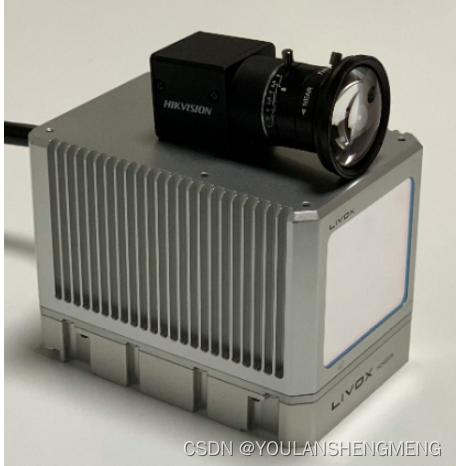
作者使用的硬件设备为:
1.2 执行标定
1)相机内参标定
将拍摄了标定板的相机的图像,放在data/camera/photos下,然后在data/camera/in.txt中写入所有需要使用的照片名称。可以使用以下的代码实现:
"""
#-*-coding:utf-8-*-
# @author: wangyu a beginner programmer, striving to be the strongest.
# @date: 2022/7/7 20:25
"""
import os

# 文件夹路径
img_path = r'/home/nvidia/calibration_ws/src/livox_camera_lidar_calibration/data/camera/photos/'
# txt 保存路径
save_txt_path = r'./in.txt'

# 读取文件夹中的所有文件
imgs = os.listdir(img_path)

# 图片名列表
names = []

# 过滤:只保留png结尾的图片
for img in imgs:
    if img.endswith(".png"):
        names.append(img)

txt = open(save_txt_path,'w')

for name in names:
    #name = name[:-4]    # 去掉后缀名.png
    txt.write(name + '\n')  # 逐行写入图片名,'\n'表示换行

txt.close()
作者使用的标定板的样子为:
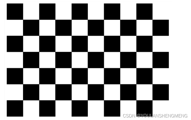
我使用的标定板, 内点是行向是9点和6点,边长是20mm
修改 对应的launch文件,如下进行修改:
<?xml version="1.0" encoding="UTF-8"?>
<launch>
    <param name="camera_in_path"        value="/home/nvidia/calibration_ws/src/livox_camera_lidar_calibration/data/camera/in.txt" />  <!-- the file to contain all the photos -->
    <param name="camera_folder_path"    value="/home/nvidia/calibration_ws/src/livox_camera_lidar_calibration/data/camera/photos/" />  <!-- the file to contain all the photos -->
    <param name="result_path"           value="/home/nvidia/calibration_ws/src/livox_camera_lidar_calibration/data/camera/result.txt" />  <!-- the file to save the intrinsic data -->

    <param name="row_number"            type="int" value="9" />  <!-- the number of block on the row -->
    <param name="col_number"            type="int" value="6" />  <!-- the number of block on the column -->
    <param name="width"                 type="int" value="20" />  <!-- the width of each block on the chessboard(mm) -->
    <param name="height"                type="int" value="20" />  <!-- the height of each block on the chessboard(mm)-->

    <node pkg="camera_lidar_calibration" name="cameraCalib" type="cameraCalib" output="screen"></node>

</launch>
执行下面的语句进行标定:
roslaunch camera_lidar_calibration cameraCalib.launch
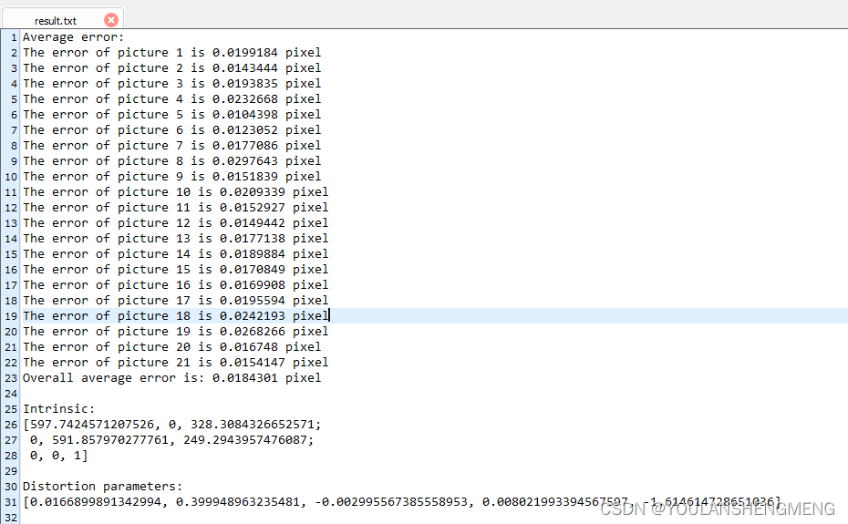
标定的结果会保存在data/camera/result.txt中,包括重投影误差,内参矩阵和畸变纠正参数。以上文件夹需要创建。
最终得到的结果如图所示:
2)准备图像中的角点坐标
首先需要把步骤2得到的内参和畸变纠正参数以下图的格式保存在data/parameters/intrinsic.txt文件下 [注 4]。distortion下面对应5个畸变纠正参数,按顺序是k1和k2 (RadialDistortion),p1和p2 (TangentialDistortion),最后一个是k3,一般默认是0
在launch文件中修改将对应的路径进行更改
<?xml version="1.0" encoding="UTF-8"?>
<launch>

    <param name="intrinsic_path"    value="/home/nvidia/calibration_ws/src/livox_camera_lidar_calibration/data/parameters/intrinsic.txt" />  <!-- intrinsic file -->
    <param name="input_photo_path"  value="/home/nvidia/LVI_ws/src/livox_camera_calib/data/frame4.png" />  <!-- photo to find the corner -->
    <param name="ouput_path"        value="/home/nvidia/calibration_ws/src/livox_camera_lidar_calibration/data/parameters/corner_photo.txt" />  <!-- file to save the photo corner -->
    <node pkg="camera_lidar_calibration" name="cornerPhoto" type="cornerPhoto" output="screen"></node>

</launch>
执行角点获取程序
roslaunch camera_lidar_calibration cornerPhoto.launch
出现的问题是,图像显示后并不能在鼠标指向的时候显示图像中的角点,解决办法,因为在源程序中经过畸变矫正的图像,所以,将程序中经过图像矫正后的图像进行保存,然后使用保存后的图像,使用以下的程序,获得4个角点的坐标。以下的代码是基于python的,使用鼠标在界面上点击图像获得图像的坐标和RGB的值。
# import cv2


# def mouse(event, x, y, flags, param):
#     if event == cv2.EVENT_LBUTTONDOWN:
#         img1 = img.copy()
#         xy = "(%d,%d)" % (x, y)  # 设置坐标显示格式
#         cv2.circle(img1, (x, y), 1, (0, 255, 0), thickness=-1)
#         cv2.putText(img1, xy, (x+10, y-10), cv2.FONT_HERSHEY_PLAIN, 2, (0, 255, 0), thickness=1)
#         cv2.imshow("image", img1)  # 显示坐标


# def get_coordinate_by_click(img_path):
#     global img
#     img = cv2.imread(img_path)  # 图片路径
#     cv2.namedWindow("image", cv2.WINDOW_AUTOSIZE)  # 设置窗口标题和大小
#     # cv2.resizeWindow('image', 1000, 400)
#     cv2.setMouseCallback("image", mouse)
#     cv2.imshow("image", img)
#     cv2.waitKey(0)
#     cv2.destroyAllWindows()


# if __name__=='__main__':
#     img_path = "/home/nvidia/LVI_ws/src/livox_camera_calib/data/frame4.png"
#     get_coordinate_by_click(img_path)

import cv2
import numpy as np

img=cv2.imread('/home/nvidia/LVI_ws/src/livox_camera_calib/data/frame4_5.png')

def on_EVENT_LBUTTONDOWN(event, x, y, flags, param):
    if event == cv2.EVENT_LBUTTONDOWN:
        xy = "%d,%d" % (x, y)
        cv2.circle(img, (x, y), 1, (255, 0, 0), thickness = -1)
        cv2.putText(img, xy, (x, y), cv2.FONT_HERSHEY_PLAIN,
                    1.0, (0,0,0), thickness = 1)
        cv2.imshow("image", img)
cv2.namedWindow("image")
cv2.setMouseCallback("image", on_EVENT_LBUTTONDOWN)
while(1):
    cv2.imshow("image", img)
    if cv2.waitKey(0)&0xFF==27:
        break
cv2.destroyAllWindows()
输入角点的坐标的方向是从左上角的点开始,逆时针的旋转 ,输入正确之后,在corner_photo.txt中就会有角点的结果

3)获得雷达点云的角点坐标
雷达的点云获取,可以参考链接:livox_camera_lidar_calibration/README_cn.md at master · Livox-SDK/livox_camera_lidar_calibration · GitHub
查看点云的方式
roslaunch livox_ros_driver livox_lidar_rviz.launch
需要录制rosbag时输入另一个命令
roslaunch livox_ros_driver livox_lidar_msg.launch
需要注意:保存的rosbag数据格式是customMsg,后续程序中处理rosbag是对应的“livox custom msg format”格式。
我直接使用了我已经转换好的PCD的文件 ,注意这里的PCD的点云,是激光长时间非重复式扫描的累加的一个文件。
使用pcl_viewer打开PCD文件,按住shift+左键点击即可获得对应的点坐标。注意和照片采用相同的角点顺序
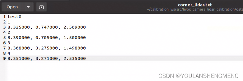
pcl_viewer -use_point_picking xx.pcd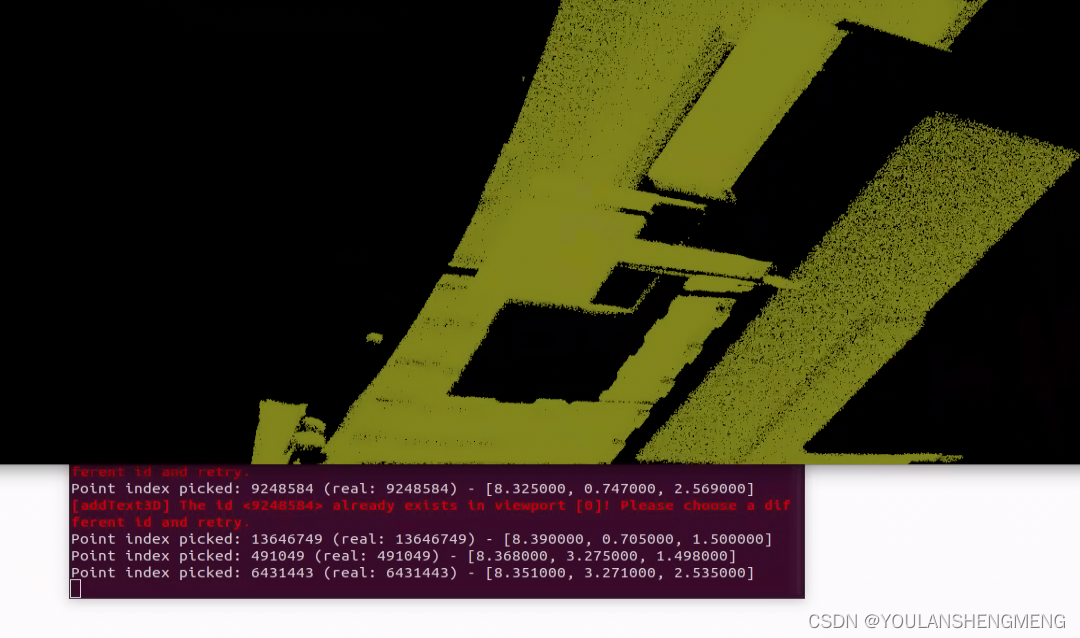 将xyz角点坐标按如下格式保存在data/corner_lidar.txt中,将所有PCD文件中雷达点云的角点坐标保存下来,如下图所示的格式:
4)相机和激光的外参标定
外参计算节点会读取data/corner_photo.txt和data/corner_lidar.txt中的标定数据来计算外参,数据需要保存成特定的格式才能被外参计算节点正确读取。参考以下格式,每行数据只有超过10个字母程序才会将其读取为计算的参数,比如下图用来编号的1234,lidar0和0.bmp这些标题不会被读取为计算参数。程序读到空行就会停止读取参数开始计算,所以保存时不要空行。在计算前检查一下雷达和相机两个标定数据中是否每行对应的是同一个角点,并检查数据量是否相同。
修改getExt1.launch文件中,对应的TXT文件的绝对路径:
<?xml version="1.0" encoding="UTF-8"?>
<launch>

    <rosparam param="init_value">  [0.0, -1.0, 0.0, 0.0,
                                    0.0, 0.0, -1.0, 0.0,
                                    1.0, 0.0, 0.0,  0.0] </rosparam>  <!-- init value of roatation matrix(3*3 on the left) and the translation(3*1 vector on the right) -->

    <param name="intrinsic_path"    value="/home/nvidia/calibration_ws/src/livox_camera_lidar_calibration/data/parameters/intrinsic.txt" />  <!-- intrinsic file -->
    <param name="extrinsic_path"    value="/home/nvidia/calibration_ws/src/livox_camera_lidar_calibration/data/parameters/extrinsic.txt" />  <!-- extrinsic file -->
    <param name="input_lidar_path"  value="/home/nvidia/calibration_ws/src/livox_camera_lidar_calibration/data/parameters/corner_lidar.txt" />  <!-- get the lidar corner data -->
    <param name="input_photo_path"  value="/home/nvidia/calibration_ws/src/livox_camera_lidar_calibration/data/parameters/corner_photo.txt" />  <!-- get the photo corner data -->
    <param name="error_threshold"    type="int" value="12" />  <!-- the threshold of the reprojection error -->

    <node pkg="camera_lidar_calibration" name="getExt1" type="getExt1" output="screen"></node>

</launch>
执行的命令:
roslaunch camera_lidar_calibration getExt1.launch
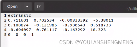
如果标定效果不好的话,就使用 getExt2节点,getExt1节点只优化外参,而getExt2节点在计算的时候会将一开始计算的内参作为初值和外参一起优化。输入指令程序会得到一个新的内参和外参,并用新的参数来进行重投影验证。一般使用getExt1节点即可,如果在外参初值验证过,并且异常值已经剔除后,优化还是有较大的残差,那么可以使用getExt2试一试。使用的前提需要保证标定数据量较大,并且要充分验证结果。
如果经过验证getExt2计算的结果确实更好,那么把新的内参更新在data/parameters/intrinsic.txt中。
1.3 标定完成后的精度验证
获得外参后我们可以用两个常见的应用看一下融合的效果。第一个是将点云投影到照片上,第二个是点云的着色
1)投影点云到照片
在projectCloud.launch文件中配置点云和照片的路径后,运行指令,将rosbag中一定数量的点投影到照片上并且保存成新的照片。
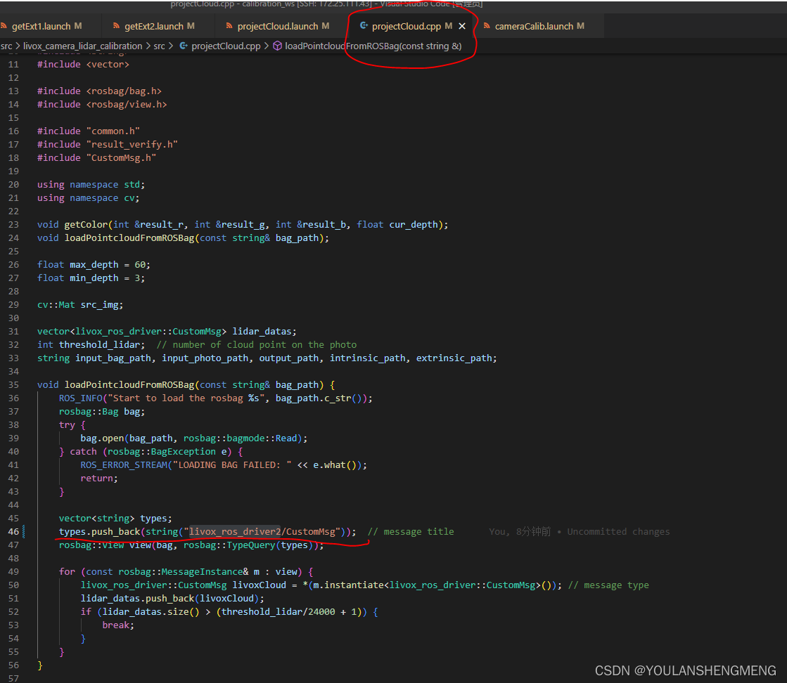
roslaunch camera_lidar_calibration projectCloud.launch注意,使用mid-360激光雷达,因为雷达的ros驱动是 livox_ros_driver2,所以需要将源码中的消息类型进行更改。使用livox_ros_driver1录制的bag包不需要进行代码修改,切记修改后需要重新标定的。
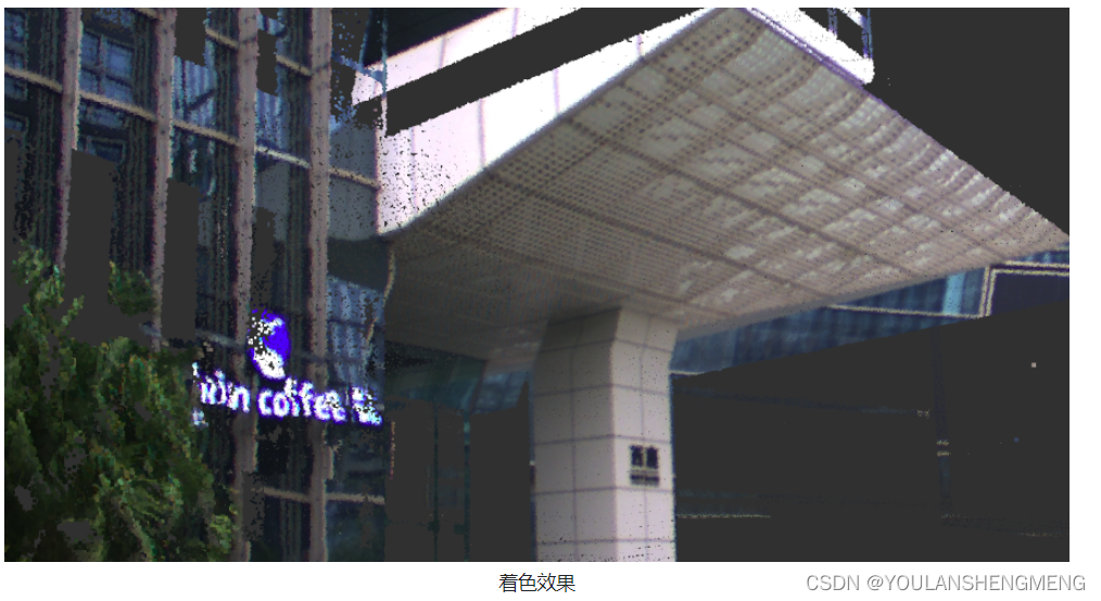
 2) 点云着色
在colorLidar.launch文件中配置点云和照片的路径,运行指令,可以在rviz中检查着色的效果。
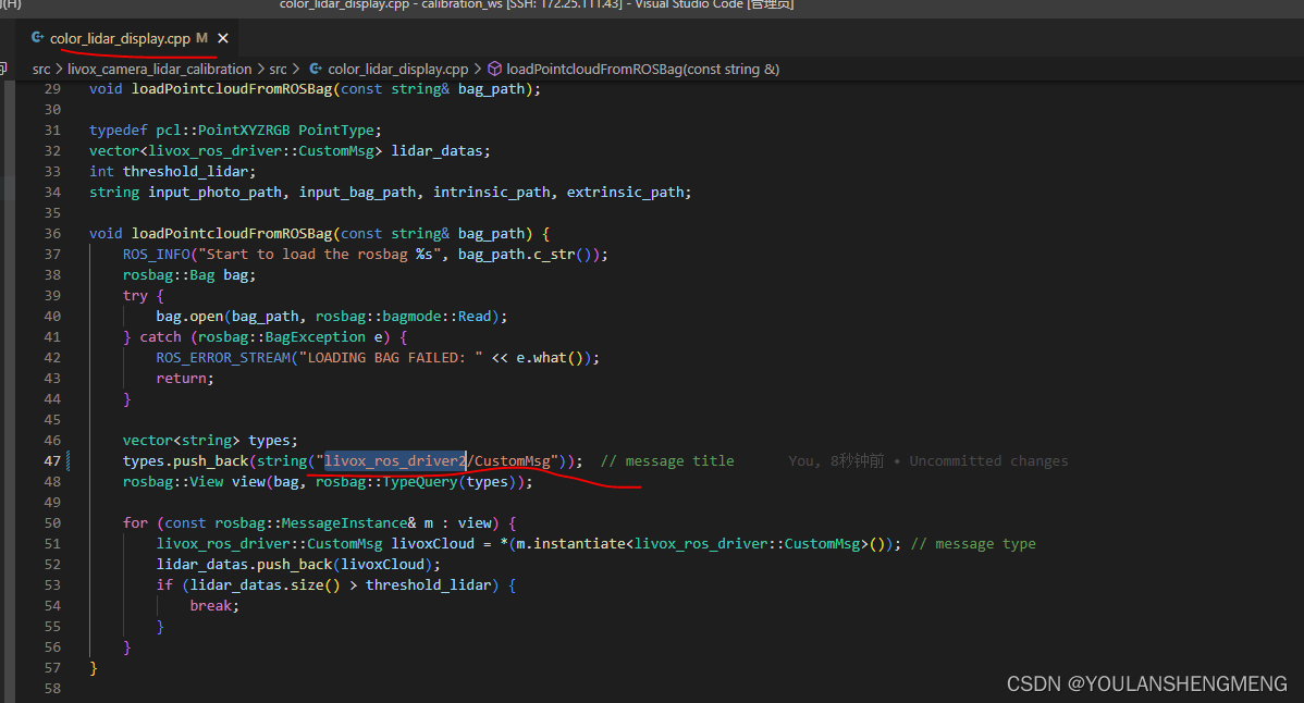
roslaunch camera_lidar_calibration colorLidar.launch同样的,如果是MID-360的话,需要进行修改
着色效果:
 1.4 总结
1. 内参矩阵的格式如下图所示,一般在(0,0);(0,2);(1,1);(1,2)四个位置有对应的值。

2. 标定的基本原理是通过同一目标物在雷达坐标系下的xyz坐标和相机坐标系下的xy坐标来计算并获得之间的转换关系。因为角点在点云和照片中都是比较明显的目标物,这样可以减少标定的误差。
3. 也可以使用多个标定板或者可以让雷达识别的棋盘格标定板。
4. 注意格式不要有变动,不然需要在程序中的common.h文件中的getIntrinsic和getDistortion程序中修改相关的代码。注意MATLAB中得到的内参矩阵是转置矩阵,输入到配置文件中时注意一下各个参数的位置。
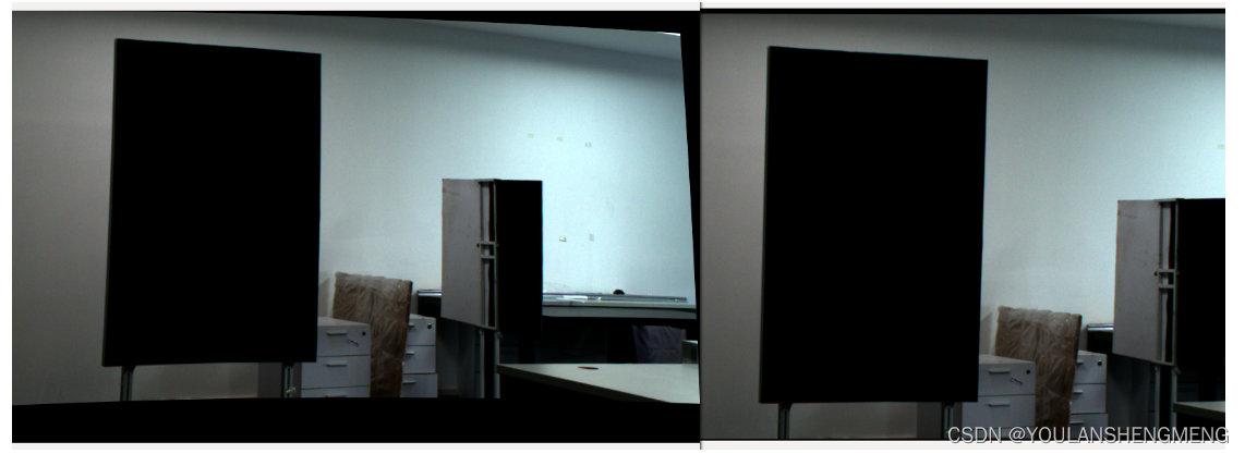
5. 显示的照片是用畸变纠正参数修正过的。检查照片修正的是否正确,比如下图中左边的照片修正的有问题,可能是畸变参数写错了。右边的照片修正是正常的。
6,打开pcl_viewer后可以输入"h"来获得指引。
7,注意少于10个字段不能被读取为计算数据,如果点云xyz或者照片xy坐标比较短需要补足10个字段。
8,程序中的默认初值是根据Livox激光雷达自身坐标系,雷达和相机的相对位置设置的,要根据情况进行修改。如果初值差的很大可能会导致不好的优化结果。
9,如果迭代结束cost还是比较大的量级(比如10的4次方), 那可能是程序中初值设置的有问题,得到的只是一个局部最优解,那么需要重新设置初值计算。
10,点云投影到照片是通过内外参矩阵将雷达的点云投影到照片对应的位置,点云的颜色会根据距离从近到远显示从蓝到红;点云的着色是通过点云的xyz和得到的内外参矩阵算出对应的相机像素坐标,获取到这个像素的RGB信息后再赋给点云显示出来,这样雷达点云可以显示真实的颜色。


