文章目录
- 1. 前言
- 2. 分析背景
- 3. 问题
- 4. 分析
- 4.1 ARM GIC 中断芯片简介
- 4.1.1 中断类型和分布
- 4.1.2 拓扑结构
- 4.2 问题根因
- 4.2.1 设置GIC `SPI` 中断CPU亲和性
- 4.2.2 GIC初始化:缺省的CPU亲和性
- 4.2.2.1 boot CPU亲和性初始化流程
- 4.2.2.1 其它非 boot CPU亲和性初始化流程
- 5. GIC 的救赎?
- 5.1 默认配置成转发给所有CPU
- 5.2 用当前 CPU ID 作为 gic_cpu_map[] 索引
- 6. 一个解决方案:irqbalance
- 7. 参考资料
1. 前言
限于作者能力水平,本文可能存在谬误,因此而给读者带来的损失,作者不做任何承诺。
2. 分析背景
本文分析基于 linux-4.14.132 内核代码分析,运行环境 Ubuntu 16.04.4 LTS + QEMU + ARM vexpress-a9 ,rootfs 基于 ubuntu-base-16.04-core-armhf.tar.gz 制作。
3. 问题
在使用全志H3机器时,观察到一个现象,外设中断总是集中在 CPU0 处理:
# cat /proc/interrupts
           CPU0       CPU1       CPU2       CPU3
 16:          0          0          0          0     GICv2  25 Level     vgic
 17:          0          0          0          0     GICv2  50 Level     /soc/timer@01c20c00
 18:          0          0          0          0     GICv2  29 Level     arch_timer
 19:       6119       3595       3947       3046     GICv2  30 Level     arch_timer
 20:          0          0          0          0     GICv2  27 Level     kvm guest timer
 22:          0          0          0          0     GICv2 120 Level     1ee0000.hdmi, dw-hdmi-cec
 24:          0          0          0          0     GICv2 118 Level     1c0c000.lcd-controller
 25:          0          0          0          0     GICv2  82 Level     1c02000.dma-controller
 26:         24          0          0          0     GICv2  92 Level     sunxi-mmc
 27:         25          0          0          0     GICv2  93 Level     sunxi-mmc
 28:       2697          0          0          0     GICv2  94 Level     sunxi-mmc
 29:          0          0          0          0     GICv2 103 Level     musb-hdrc.4.auto
 30:          0          0          0          0     GICv2 104 Level     ehci_hcd:usb1
 31:          0          0          0          0     GICv2 105 Level     ohci_hcd:usb2
 32:          0          0          0          0     GICv2 106 Level     ehci_hcd:usb3
 33:          0          0          0          0     GICv2 107 Level     ohci_hcd:usb6
 34:          0          0          0          0     GICv2 108 Level     ehci_hcd:usb4
 35:          0          0          0          0     GICv2 109 Level     ohci_hcd:usb7
 36:          0          0          0          0     GICv2 110 Level     ehci_hcd:usb5
 37:          0          0          0          0     GICv2 111 Level     ohci_hcd:usb8
 40:        205          0          0          0     GICv2  63 Level     1c25000.ths
 42:       1802          0          0          0     GICv2 114 Level     eth0
 43:          0
我们观察到,除了第6行
19: 6119 3595 3947 3046 GICv2 30 Level arch_timer
之外,其它所有的行,CPU1~CPU3 的中断计数都为0。另外,用 QEMU 模拟的 vexpress-a9 板上,也观察到类似的现象:
$ cat /proc/interrupts
           CPU0       CPU1       CPU2       CPU3
 16:      69412      69401      69376      69332     GIC-0  29 Level     twd
 17:          6          0          0          0     GIC-0  34 Level     timer
 27:          0          0          0          0     GIC-0  92 Level     arm-pmu
 28:          0          0          0          0     GIC-0  93 Level     arm-pmu
 29:          0          0          0          0     GIC-0  94 Level     arm-pmu
 30:          0          0          0          0     GIC-0  95 Level     arm-pmu
 34:       3521          0          0          0     GIC-0  41 Level     mmci-pl18x (cmd)
 35:     197190          0          0          0     GIC-0  42 Level     mmci-pl18x (pio)
 36:          8          0          0          0     GIC-0  44 Level     kmi-pl050
 37:        100          0          0          0     GIC-0  45 Level     kmi-pl050
 38:         23          0          0          0     GIC-0  37 Level     uart-pl011
 44:          0          0          0          0     GIC-0  36 Level     rtc-pl031
IPI0:          0          1          1          1  CPU wakeup interrupts
IPI1:          0          0          0          0  Timer broadcast interrupts
IPI2:        750       1231       1441        947  Rescheduling interrupts
IPI3:          1          2          3          3  Function call interrupts
IPI4:          0          0          0          0  CPU stop interrupts
IPI5:          0          0          0          0  IRQ work interrupts
IPI6:          0          0          0          0  completion interrupts
Err:          0
4. 分析
4.1 ARM GIC 中断芯片简介
4.1.1 中断类型和分布
我们这里讨论的是 ARM GICv1 芯片,该芯片的中断分为3类:
SGI(Software-generated interrupt):用于处理期之间的通信,编号为 0~15 ;
PPI(Private peripheral interrupt):发送到特定处理器的中断,编号为 16~31 ;
SPI(Shared peripheral interrupt):可以发送给所有处理器的中断,编号为 32~1019 。
注意,每个处理器都有自己的 SGI 和 PPI 中断,它们使用相同的编号。假设系统有4个处理器,则这4个处理器都有自己的16个 SGI 中断和16个 PPI 中断。SPI 中断是全局的、所有处理器共享的。
4.1.2 拓扑结构
ARM GIC 芯片的内部结构如下图:
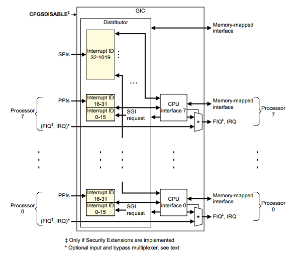
GIC 芯片内部包含两大功能模块:Distributor 和 CPU interface 。Distributor 用于将外设投递的中断信号转发给 CPU interface,具体转发给哪些 CPU interface ,可通过寄存器 ICDIPTRn 进行配置,当然,Distributor 也可以禁止外设中断信号的传入。而 CPU interface 用于将接收自 Distributor 的中断信号传递给连接的 CPU, CPU interface 也可以禁止将信号传递给 CPU 。
4.2 问题根因
4.2.1 设置GIC SPI 中断CPU亲和性
从上一小节了解到,具体将中断转发给哪个 CPU 核处理,取决于寄存器 ICDIPTRn 的配置。看一下 GIC 手册对该寄存器的描述:
4.3.11 Interrupt Processor Targets Registers (ICDIPTRn)
       The ICDIPTR characteristics are:
Purpose                     The ICDIPTRs provide an 8-bit CPU targets field for each interrupt supported by
                            the GIC. This field stores the list of processors that the interrupt is sent to if it is
                            asserted.

准确来讲,这是一个寄存器集,可以按字节访问,每个字节对应一个中断号的 Distributor 转发配置,每个bit对应一个CPU核的配置,最多支持8核。对于 SGI 和 PPI 中断号区间对应的寄存器,它们是每个CPU一份的(上面的引用没有描述),而对于 SPI 中断号区间对应的寄存器,它们的所有CPU共享一份的。GIC 芯片驱动提供接口 gic_set_affinity() 来配置 Distributor ICDIPTRn 寄存器,来决定 Distributor 将中断信号转发给哪个CPU核来处理,来看它的逻辑:
int cpumask_next_and(int n, const struct cpumask *src1p,
		     const struct cpumask *src2p)
{
	while ((n = cpumask_next(n, src1p)) < nr_cpu_ids)
		if (cpumask_test_cpu(n, src2p))
			break;
	return n;
}

/**
 * cpumask_next_and - get the next cpu in *src1p & *src2p
 * @n: the cpu prior to the place to search (ie. return will be > @n)
 * @src1p: the first cpumask pointer
 * @src2p: the second cpumask pointer
 *
 * Returns >= nr_cpu_ids if no further cpus set in both.
 */
int cpumask_next_and(int n, const struct cpumask *src1p,
		     const struct cpumask *src2p)
{
	while ((n = cpumask_next(n, src1p)) < nr_cpu_ids)
		if (cpumask_test_cpu(n, src2p))
			break;
	return n;
}

/**
 * cpumask_first_and - return the first cpu from *srcp1 & *srcp2
 * @src1p: the first input
 * @src2p: the second input
 *
 * Returns >= nr_cpu_ids if no cpus set in both.  See also cpumask_next_and().
 */
#define cpumask_first_and(src1p, src2p) cpumask_next_and(-1, (src1p), (src2p))

/**
 * cpumask_any_and - pick a "random" cpu from *mask1 & *mask2
 * @mask1: the first input cpumask
 * @mask2: the second input cpumask
 *
 * Returns >= nr_cpu_ids if no cpus set.
 */
/* 这个注释里的 "random" 真是个误导,从来也存在什么随机可言 */
#define cpumask_first_and(src1p, src2p) cpumask_next_and(-1, (src1p), (src2p))

/**
 * cpumask_first - get the first cpu in a cpumask
 * @srcp: the cpumask pointer
 *
 * Returns >= nr_cpu_ids if no cpus set.
 */
static inline unsigned int cpumask_first(const struct cpumask *srcp)
{
	return find_first_bit(cpumask_bits(srcp), nr_cpumask_bits);
}

static int gic_set_affinity(struct irq_data *d, const struct cpumask *mask_val,
			    bool force)
{
	/* 计算中断 @d->hwirq 的 ICDIPTRn 寄存器地址 */
	void __iomem *reg = gic_dist_base(d) + GIC_DIST_TARGET + (gic_irq(d) & ~3);
	/* ICDIPTRn 是 32-bit 寄存器,包含4个中断的设置,要计算中断 @d->hwirq 配置域的位偏移 */
	unsigned int cpu, shift = (gic_irq(d) % 4) * 8;
	u32 val, mask, bit;
	unsigned long flags;

	/*
	 * 从 @mask_val 选一个 CPU,然后用它的转发配置来配置对中断 @d->hwirq 的转发。
	 * 这里就是导致 SPI 中断都转发给 CPU0 的根因了。force 可能是 true ,也可能是
	 * false ,看起来似乎得到的 @cpu 的值会是变化的。
	 * SPI 中断初始化从 request_irq*() 系列调用发起,在过程中会设置 SPI 中断的CPU
	 * 亲和性,传进来的 @mask_val 掩码包含系统所有的 CPU,这样在这里得到的 @cpu 均
	 * 为 0 (假定 CPU0 是 boot CPU,这是通常的情形) !!!
	 * 当然,从 request_percpu_irq() 注册的每 CPU 中断是例外。
	 */
	if (!force)
		cpu = cpumask_any_and(mask_val, cpu_online_mask);
	else
		cpu = cpumask_first(mask_val);

	...

	mask = 0xff << shift;
	/*
	 * 这个逻辑,说实话,很是违反人类的直觉(至少是我的)。 譬如,用户空间通过指令
	 * echo f > /proc/irq/38/smp_affinity
	 * 来配置38号中断的 CPU affinity (即 Distributor 转发38号中断给哪些CPU核),
	 * 我理解的是可以将38号中断发送给 CPU0~3 中的任一个来处理。
	 * 但最终发生了什么呢?GIC 驱动代码仅仅是从掩码计算出一个编号 @cpu ,然后以
	 * @cpu 为索引,取值 @gic_cpu_map[@cpu] 来配置中断 @d->hwirq 的 Distributor
	 * 的转发配置:发送中断 @d->hwirq 给哪些 CPU !!! 呵呵,完全出乎意料。
	 * 从前面的代码片段了解到,除非特殊配置,索引值 @cpu 总是返回 0,这意味着,驱动
	 * 总是将 SPI 中断的转发配置为固定值 @gic_cpu_map[@cpu] ,也就是 SPI 中断总是
	 * 被某几个或某个CPU核处理,最终结果是 SPI 中断总是被 CPU0 处理。
	 * 从哪里知道固定值 @gic_cpu_map[@cpu] 是固定值,而且是 0x01 这个固定值(假设
	 * boot CPU 是 CPU0)?简略的看后面中断初始化的流程,可以了解这些。
	 */
	bit = gic_cpu_map[cpu] << shift;
	val = readl_relaxed(reg) & ~mask;
	writel_relaxed(val | bit, reg);
	...

	irq_data_update_effective_affinity(d, cpumask_of(cpu));

	return IRQ_SET_MASK_OK_DONE;
}
4.2.2 GIC初始化:缺省的CPU亲和性
4.2.2.1 boot CPU亲和性初始化流程
int __init
gic_of_init(struct device_node *node, struct device_node *parent)
{
	...

	ret = __gic_init_bases(gic, -1, &node->fwnode);

	...
}

static int __init __gic_init_bases(struct gic_chip_data *gic,
				   int irq_start,
				   struct fwnode_handle *handle)
{
	if (gic == &gic_data[0]) { /* ROOT 中断控制器 */
		for (i = 0; i < NR_GIC_CPU_IF; i++)
			gic_cpu_map[i] = 0xff; /* 初始将中断转发给所有 CPU interface 上的 CPU */
		...
		/* 设置非 boot CPU 中断初始化入口 gic_starting_cpu() */
		cpuhp_setup_state_nocalls(CPUHP_AP_IRQ_GIC_STARTING,
					  "irqchip/arm/gic:starting",
					  gic_starting_cpu, NULL);
		set_handle_irq(gic_handle_irq); /* 设置中断 GIC 中断处理入口 */
		...
	}

	...

	ret = gic_init_bases(gic, irq_start, handle);
	ret = gic_cpu_init(gic);

	...
}

static int gic_init_bases(struct gic_chip_data *gic, int irq_start,
			  struct fwnode_handle *handle)
{
	...

	cpumask = gic_get_cpumask(gic); /* 读取当前 CPU 的默认中断转发配置 */
	/* 将 gic_get_cpumask() 读回的 8-bit 值复制到 32-bit @cpumask
	 * 的所有 4个 8-bit 域 */
	cpumask |= cpumask << 8;
	cpumask |= cpumask << 16;
	/*
	 * 默认的 Distributor 转发配置:只将中断转发给 boot CPU。
	 * 这是合理的,因为当前处于 boot 阶段,除 boot CPU 外的其它CPU还没有运行起来。
	 */
	for (i = 32; i < gic_irqs; i += 4)
		writel_relaxed(cpumask, base + GIC_DIST_TARGET + i * 4 / 4);

	...
}

/* 读取当前 CPU 的默认中断转发配置 */
static u8 gic_get_cpumask(struct gic_chip_data *gic)
{
	/*
	 * 这里的代码,如果没读过 GIC 手册,是比较难理解的。
	 * 这里读的是 CPU 私有中断 SGI,PPI 的转发配置值,它们的理所当然的是只会
	 * 转发给对应的 CPU 核,譬如编号为 29 的 PPI 中断:
	 * . CPU0 读到的值就应该是 0xXX_XX_01_XX
	 * . CPU1 读到的值就应该是 0xXX_XX_02_XX
	 * . CPU2 读到的值就应该是 0xXX_XX_04_XX
	 * . CPU3 读到的值就应该是 0xXX_XX_08_XX
	 * 对于 SGI,PPI 这些私有中断,寄存器是多份的(banked register),所以不同的CPU
	 * 在这里读的是自己私有的寄存器;而 SPI 中断的寄存器是全局独一份的。
	 */
	for (i = mask = 0; i < 32; i += 4) {
		/*
		 * 对于不同的 SPI 中断号,读到值的不为 0 的 8-bit 的位偏移位置不同,
		 * 后面的移位操作是为了保证将不为 0 的 8-bit 移动到最低 8-bit 。
		 * 为什么?因为返回值类型是 u8 。
		 */
		mask = readl_relaxed(base + GIC_DIST_TARGET + i);
		mask |= mask >> 16;
		mask |= mask >> 8;
		/*
		 * 为什么 @mask 不为 0 就返回了?
		 * 因为只要是同一 CPU 核,只要读到某个 SGI 或 PPI 中断的转发配置值不为0,剩余
		 * 其它 SGI 或 PPI 中断配置值一定是相同的。这里只是要取得当前 CPU 的某个 SGI
		 * 或 PPI 中断转发配置值就够了。
		 * 那又为什么不直接根据 CPU ID 返回 0x01, 0x02, 0x04, 0x08, ... 这样的值呢?
		 * 因为 SGI 或 PPI 中断转发配置寄存器的值它们是【只读的】,具体的值是由硬件设
		 * 计决定的,有可能 CPU0 读到的值是 0x02 ,因为 GIC 的 CPU interface 0 有可
		 * 能连接到 CPU1 ,这在理论上是可能出现的。
		 */
		if (mask) /* 硬件实现了某 SGI, PPI 中断的映射,即中断转发配置不为0值 */
			break;
	}

	return mask;
}

static int gic_cpu_init(struct gic_chip_data *gic)
{
	if (gic == &gic_data[0]) {
		cpu_mask = gic_get_cpumask(gic);
		gic_cpu_map[cpu] = cpu_mask; /* 当前 CPU @cpu 中断的默认转发配置:只转发给自身 */

		/*
		 * Clear our mask from the other map entries in case they're
		 * still undefined.
		 */
		for (i = 0; i < NR_GIC_CPU_IF; i++)
			if (i != cpu)
				gic_cpu_map[i] &= ~cpu_mask;
	}
	...
}
4.2.2.1 其它非 boot CPU亲和性初始化流程
secondary_start_kernel()
	notify_cpu_starting(cpu)
		struct cpuhp_cpu_state *st = per_cpu_ptr(&cpuhp_state, cpu);
		enum cpuhp_state target = min((int)st->target, CPUHP_AP_ONLINE);

		...
		while (st->state < target) {
			st->state++;
			ret = cpuhp_invoke_callback(cpu, st->state, true, NULL, NULL);
				...
				gic_starting_cpu(cpu)
		}
		...
static int gic_starting_cpu(unsigned int cpu)
{
	gic_cpu_init(&gic_data[0]); /* 见 4.2.2.1 章节分析 */
	return 0;
}
总结起来就是,在 boot CPU 为 CPU0 的情形下,所有 SPI 中断的 ICDIPTRn 寄存器 都配置为 gic_cpu_map[0] == 0x01 ,即将所有 SPI 中断都转发给 CPU0 处理。SGI 和 PPI 中断不在我们考虑范围之内,因为它们本来就是特定于 CPU 的。
5. GIC 的救赎?
以下测试均基于 QEMU 模拟的 vexpress-a9 开发板 。
5.1 默认配置成转发给所有CPU
这看起来是比较合理的解决方案,对 GIC 驱动的 gic_set_affinity() 接口做如下修改:
- bit = gic_cpu_map[cpu] << shift;
+ bit = 0xff << shift; /* 默认转发给所有的 CPU */
我们来看一下实际效果:
$ cat /proc/interrupts
           CPU0       CPU1       CPU2       CPU3
 16:       4558       4548       4578       4505     GIC-0  29 Level     twd
 17:          6          0          0          0     GIC-0  34 Level     timer
 27:          0          0          0          0     GIC-0  92 Level     arm-pmu
 28:          0          0          0          0     GIC-0  93 Level     arm-pmu
 29:          0          0          0          0     GIC-0  94 Level     arm-pmu
 30:          0          0          0          0     GIC-0  95 Level     arm-pmu
 34:       1426       1146       1275       1308     GIC-0  41 Level     mmci-pl18x (cmd)
 35:      81272      78233      77890      78991     GIC-0  42 Level     mmci-pl18x (pio)
 36:          0          0          8          0     GIC-0  44 Level     kmi-pl050
 37:          0          0         99          1     GIC-0  45 Level     kmi-pl050
 38:         18          3          0          2     GIC-0  37 Level     uart-pl011
 44:          0          0          0          0     GIC-0  36 Level     rtc-pl031
IPI0:          0          1          1          1  CPU wakeup interrupts
IPI1:          0          0          0          0  Timer broadcast interrupts
IPI2:        750        501        548        864  Rescheduling interrupts
IPI3:          0          2          2          1  Function call interrupts
IPI4:          0          0          0          0  CPU stop interrupts
IPI5:          0          0          0          0  IRQ work interrupts
IPI6:          0          0          0          0  completion interrupts
Err:          0
看起来不错,SPI 中断的处理,已经散落到各个 CPU 核上了。如果…,但世界上没有如果,由于 GIC 芯片设计的缺陷,当配置多个 CPU 接收中断的时候,所有这些 CPU 核在中断发生时,都来争抢处理进入的中断,当然最终只会有一个CPU获得胜利,其它的核白白的在那里浪费时间。如果某核当前正在睡眠,如执行了 WFI,WFE 指令,就会造成能耗,这在很多设备是电池供电的嵌入式环境下,也是不合适的。看看 Russell King 的解释:
The behaviour of the GIC is as follows. If you set two CPUs in
GICD_ITARGETSRn, then the interrupt will be delivered to _both_ of
those CPUs. Not just one selected at random or determined by some
algorithm, but both CPUs.

Both CPUs get woken up if they're in sleep, and both CPUs attempt to
process the interrupt. One CPU will win the lock, while the other CPU
spins waiting for the lock to process the interrupt.

The winning CPU will process the interrupt, clear it on the device,
release the lock and acknowledge it at the GIC CPU interface.

The CPU that lost the previous race can now proceed to process the
very same interrupt, discovers that it's no longer pending on the
device, and signals IRQ_NONE as it appears to be a spurious interrupt.

The result is that the losing CPU ends up wasting CPU cycles, and
if the losing CPU was in a low power idle state, needlessly wakes up
to process this interrupt.

If you have more CPUs involved, you have more CPUs wasting CPU cycles,
being woken up wasting power - not just occasionally, but almost every
single interrupt that is raised from a device in the system.

On architectures such as x86, the PICs distribute the interrupts in
hardware amongst the CPUs. So if a single interrupt is set to be sent
to multiple CPUs, only _one_ of the CPUs is actually interrupted.
Hence, x86 can have multiple CPUs selected as a destination, and
the hardware delivers the interrupt across all CPUs.

On ARM, we don't have that. We have a thundering herd of CPUs if we
set more than one CPU to process the interrupt, which is grossly
inefficient.
原文见此处。
5.2 用当前 CPU ID 作为 gic_cpu_map[] 索引
对 GIC 驱动的 gic_set_affinity() 接口做如下修改:
- if (!force)
-	cpu = cpumask_any_and(mask_val, cpu_online_mask);
- else
-	cpu = cpumask_first(mask_val);
+ cpu = smp_processor_id();
将当前 CPU ID 作为数组 gic_cpu_map[] 的索引,这样 SPI 中断不会集中到 CPU0 上。看一下实际效果:
$ cat /proc/interrupts
           CPU0       CPU1       CPU2       CPU3
 16:       7626       7583       7531       7495     GIC-0  29 Level     twd
 17:          6          0          0          0     GIC-0  34 Level     timer
 27:          0          0          0          0     GIC-0  92 Level     arm-pmu
 28:          0          0          0          0     GIC-0  93 Level     arm-pmu
 29:          0          0          0          0     GIC-0  94 Level     arm-pmu
 30:          0          0          0          0     GIC-0  95 Level     arm-pmu
 34:          0          0          0       2912     GIC-0  41 Level     mmci-pl18x (cmd)
 35:          0          0          0     204459     GIC-0  42 Level     mmci-pl18x (pio)
 36:          0          0          0          8     GIC-0  44 Level     kmi-pl050
 37:          0          0          0        100     GIC-0  45 Level     kmi-pl050
 38:         23          0          0          0     GIC-0  37 Level     uart-pl011
 44:          0          0          0          0     GIC-0  36 Level     rtc-pl031
IPI0:          0          1          1          1  CPU wakeup interrupts
IPI1:          0          0          0          0  Timer broadcast interrupts
IPI2:       1423       1288       1527        360  Rescheduling interrupts
IPI3:          1          2          2          1  Function call interrupts
IPI4:          0          0          0          0  CPU stop interrupts
IPI5:          0          0          0          0  IRQ work interrupts
IPI6:          0          0          0          0  completion interrupts
Err:          0
SPI 中断集中在 CPU0,CPU3 两个核上处理,但至少不会集中在同一个核上了。一个改进思路是记录每个核上当前转发的 SPI 个数,然后将它们均匀的散落到各个核上,这其实有点类似于我们后面即将提到的 irqbalance 了。但这并不值得提倡,因为这意味将机制实现在内核中,限制了用户空间的灵活性,内核应该只提供策略,而实现留给用户空间。
6. 一个解决方案:irqbalance
使用 irqbalance 是一个常见的解决方案,它的实现时监控 CPU 上的中断处理状况,通过 /proc/irq/N/smp_affinity 或 /proc/irq/N/smp_affinity_list 对中断进行显式配置,让它们均匀的散落到各个 CPU 上去。
irqbalance 是完美的吗?由于可能会经常的改变中断转发的 CPU,所以也会影响到数据访问的本地 cache 命中率,在网络场景下,可能对性能造成损害。世界就是这样,总是这么复杂,没有什么是完美无缺的。
7. 参考资料
《IHI0048A_gic_architecture_spec_v1_0.pdf》
《DDI0471A_gic400_r0p0_trm.pdf》

