Arduino PID
- Arduino-PID-Library
- Arduino-PID-AutoTune-Library
PID控制实验 – 制作测试台
PID Control Experiment – Making the Testing Rig

PID (Proportional, Integral, Derivative) control is a classic control algorithm that I have used for a few projects, ending with ‘good enough’ control, without really spending time learning how to properly tune the PID constants.
PID(Proportional, Integral, Derivative)控制是我用于一些项目的经典控制算法,以“足够好”的控制结束,而没有真正花时间学习如何正确调整 PID 常数。
Time for me to fill in the gap in my knowledge, so in this two part blog I want to capture my learning. Hopefully it is useful for someone else. In this first part I will document the learning and testing rig and software. The next part will be about tuning the control loop.
是时候填补我的知识空白了,所以在这个由两部分组成的博客中,我想捕捉我的学习成果。希望它对其他人有用。在第一部分中,我将记录学习和测试设备及软件。下一部分将是关于调整控制环路的。
Principles of Control 控制原则
Any feedback control loop basically works like the diagram below
任何反馈控制回路基本上都如下图所示
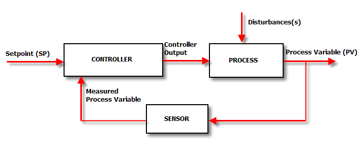
The Set Point (SP) is the value that we want the process to be. The controller compares the SP with the actual value of the Process Variable (PV). If SP = PV the controller doesn’t have to do anything and it will maintain the Controller Output (CO) at the current level (or set it to zero).
设定点 (SP) 是我们希望过程达到的值。控制器将 SP 与过程变量 (PV) 的实际值进行比较。如果 SP = PV,则控制器无需执行任何操作,它将控制器输出 (CO) 保持在当前水平(或将其设置为零)。
If SP ≠ PV, this is expressed as an error or deviation and needs corrective action. This action takes place in the Controller, which changes the CO until SP = CV again. If a disturbance (like a change in SP, or an external event) occurs the controller has to work it out all over again. In practice the control loop operates continuously to fine tune the CO.
如果 SP ≠ PV,则表示为错误或偏差,需要采取纠正措施。此操作在控制器中发生,该控制器会更改 CO,直到再次更改 SP = CV。如果发生干扰(如 SP 的变化或外部事件),控制器必须重新解决。在实践中,控制回路连续运行以微调 CO。
Test Rig System Design 试验台系统设计
The description above implies the testing rig needs to have certain characteristics to provide a valid learning platform:
上述描述意味着测试设备需要具有某些特性才能提供有效的学习平台:
- A repeatable process. Doing the same thing will result in the same system response, allowing it to be controlled.
一个可重复的过程。做同样的事情将导致相同的系统响应,允许它被控制。 - Allow the creation of system disturbance to test the control response.
允许创建系统扰动以测试控制响应。 - Be cheap, simple and easy to build.
便宜、简单且易于构建。 - As this is an Arduino project, be suitable for digital control.
由于这是一个Arduino项目,因此适合数字控制。
Somewhere in my web browsing I had come across an idea for a project that seemed to suit this application. The project involved a fan blowing into a vertical clear plastic pipe from below to keep a table tennis ball at a set height in the pipe.
在我的网页浏览中,我遇到了一个似乎适合此应用程序的项目的想法。该项目涉及一个风扇从下方吹入垂直的透明塑料管,以将乒乓球保持在管道中的设定高度。
Providing the ball is a loose fit in the tube, this arrangement is inherently unstable and will cause it’s own disturbance. Also, the ball ‘floats’ because of the fan air pressure below and I would expect that the higher it would go up the tube the more unstable it would be (which was found to be true in practice).
如果球在管子中是松散的,这种布置本质上是不稳定的,并且会引起它自身的干扰。此外,由于下方的风扇气压,球会“漂浮”,我预计球在管子上的上升幅度越高,它就越不稳定(这在实践中被发现是正确的)。
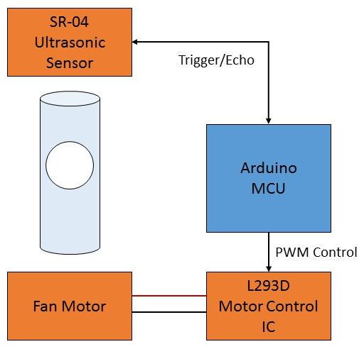
The control feedback is a simple distance measurement and the control output is a signal for fan speed, both of which are eminently doable with an Arduino Uno processor.
控制反馈是一个简单的距离测量,控制输出是风扇速度的信号,这两者都非常适合使用 Arduino Uno 处理器。
The block diagram for the system is shown on the right. Except for the tube, all the other materials were already at hand. A table tennis ball had a 40mm diameter and standard tube is available with 45mm internal diameter – perfect!
系统的框图如右图所示。除了管子,所有其他材料都已经手头了。乒乓球的直径为 40 毫米,标准管的内径为 45 毫米——完美!
The ultrasonic sensor is a very cheap and commonly available SR-04. The fan was a small 24V laptop cooling fan I salvaged some time ago.
超声波传感器是一种非常便宜且常用的 SR-04。风扇是我前段时间打捞的小型 24V 笔记本电脑冷却风扇。
The L293D motor controller was from my parts stock. It simplifies the design of the hardware as it has built-in motor output diodes. An alternative is a transistor or MOSFET based switching circuit.
L293D 电机控制器来自我的零件库存。它简化了硬件的设计,因为它具有内置的电机输出二极管。另一种选择是基于晶体管或MOSFET的开关电路。
Making the Test Rig 制作测试台
The stand for the equipment was made from wood and plywood scraps, glued and screwed. construction is self-explanatory by looking at the pictures below – not pretty but it works.
设备的支架由木材和胶合板废料制成,经过胶合和拧紧。通过查看下面的图片,建筑是不言自明的——虽然不漂亮,但它有效。
No dimensions are critical except for the distance between the top of the tube and the sensor. The sensor has to be far enough not to block airflow out of the tube, which stops the ball from rising, and close enough that the ultrasonic ‘pings’ go into the tube and don’t hit the top rim. Some trial and error found a sweet spot that worked.
除了管子顶部和传感器之间的距离外,没有尺寸是关键的。传感器必须足够远,以免阻挡气流从管子中流出,从而阻止球上升,并且必须足够近,以便超声波“砰砰”声进入管子并且不会撞击顶部边缘。经过反复试验,我们发现了一个有效的最佳点。

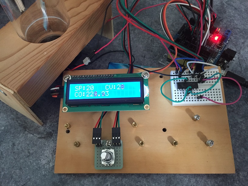
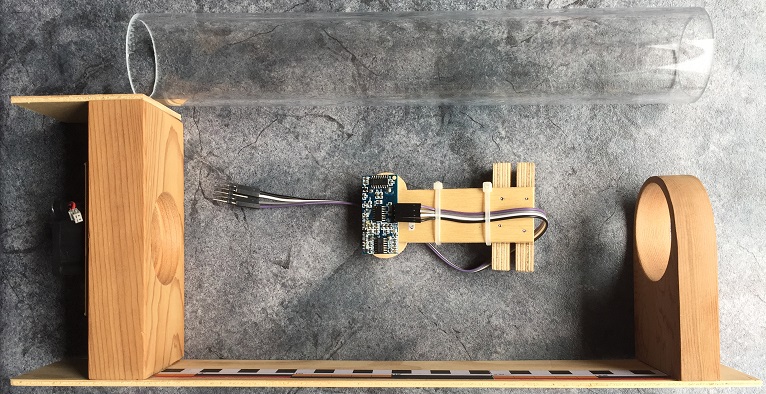
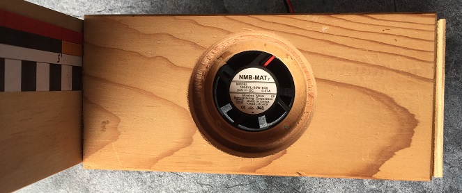
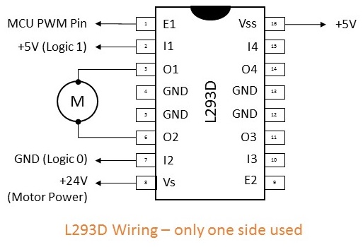
The L293D is wired as per the diagram on the left. In the photo this IC is on the mini-breadboard. The L293D direction controls I1 and I2 are connected to 5V and GND as the fan is not reversible. The Arduino PWM (Control Output) pin is connected to the enable pin to provide the required fan speed control. The 5V power supply for the control circuit comes from the USB interface on the Arduino. The 24V motor supply is from a bench top power supply.
L293D 的接线如左图所示。在照片中,该IC位于迷你面包板上。L293D 方向控制器 I1 和 I2 连接到 5V 和 GND,因为风扇是不可逆的。Arduino PWM(控制输出)引脚连接到使能引脚,以提供所需的风扇速度控制。控制电路的5V电源来自Arduino上的USB接口。24V电机电源来自台式电源。
Control Software 控制软件
Finally, the control sketch needs to do a few things other than just run the PID control.
最后,控制草图需要做一些事情,而不仅仅是运行 PID 控制。
- To make this an effective learning rig, the PID constants and the set point should be editable without recompiling and downloading application.
为了使它成为一个有效的学习设备,PID常数和设定点应该是可编辑的,而无需重新编译和下载应用程序。 - The software should log data to the Serial Monitor so that it can be graphed offline or charted with the Arduino IDE Serial Plotter. This should be controllable (on/off) as there is likely to be a lot of data.
该软件应将数据记录到串行监视器中,以便可以离线绘制数据或使用 Arduino IDE 串行绘图仪绘制数据。这应该是可控的(开/关),因为可能会有大量数据。 - Once optimized, PID parameters can be saved to EEPROM and will be reloaded at the next system restart.
经过优化后,PID参数可以保存到EEPROM中,并在下次系统重启时重新加载。
The LCD display and the rotary encoder implement a user interface for a menu options that allow the online changes required.
LCD 显示屏和旋转编码器实现了菜单选项的用户界面,允许进行所需的在线更改。
The full sketch is available from my code repository.
完整的草图可从我的代码库中找到。
下面,该设备将用于实验。
PID 控制实验 - 整定
Arduino — PID Control Experiment – Tuning the Controller)
PID(比例、积分、微分)控制是一种经典的控制算法,我曾在几个项目中使用过这种算法,但都以 "足够好 "的控制而告终,并没有真正花时间学习如何正确调整 PID 常量。 是时候填补我的知识空白了,所以在这篇分为两部分的博客中,我希望 […]
In the first part of this blog I described building a test apparatus that allows me to experiment with tuning a PID loop controlling a levitating pin pong ball in a tube.
在本博客的第一部分,我介绍了如何构建一个测试设备,该设备使我能够试验调整PID环路,以控制管中的悬浮针乒球。
What does “Tuning a PID Controller” mean?
I won’t cover the theory of PID controllers – there is a lot of material already available ([1] is a good overview), but in general a PID controller is configured using three parameters acting in sum to close the loop error – proportional gain (Kp), integral time (Ti), and derivative time (Td).
我不会介绍PID控制器的理论 - 已经有很多材料可用([1]是一个很好的概述),但总的来说,PID控制器使用三个参数进行配置,这些参数相加以闭合环路误差 - 比例增益(Kp),积分时间(Ti)和导数时间(Td)。
Keeping it simple: 保持简单:
- The proportional action Kp will reduce the steady state error. Increasing Kp reduces rise time – the controller responds more aggressively to the error.
比例作用 Kp 将减小稳态误差。增加 Kp可缩短上升时间 – 控制器对误差的响应更积极。 - The derivative action Td interprets the change of slope of error changes. Td is the look-ahead time to try to estimate future system behavior. Large values of Td create overshoots as it ‘guesses’ wrongly.
导数作用 Td 解释误差变化的斜率变化。Td 是尝试估计未来系统行为的预见时间。较大的 Td 值会产生超调,因为它会“猜错”。 - Ti eliminates steady state error and reduces rise time. Ti may improve the response of the system but it is a little bit tricky and PD control is often sufficient.
Ti 消除了稳态误差并缩短了上升时间。我可能会提高系统的响应,但这有点棘手,PD控制通常就足够了。
These parameters can be derived from models of the process being controlled. However, as this does not apply in many to the kinds of systems I build, I will be looking at heuristic (trial and error) methods for estimating the values.
这些参数可以从被控制过程的模型中得出。但是,由于这在许多系统中并不适用于我构建的各种系统,因此我将研究用于估计值的启发式(试错)方法。
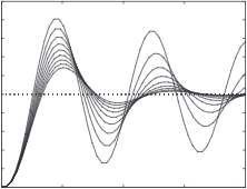
Tuning the loop is about finding a combination of these three parameters that gives an appropriate response to a disturbance, as illustrated in the figure below. The ‘right’ response depends on what the loop is controlling (objective) and the expectations of the person doing the tuning (subjective).
整定就是要找到这三个参数的组合,以便对干扰做出适当的响应,如下图所示。“正确”的响应取决于循环控制的内容(客观的)和进行调整的人的期望(主观)。

For the purpose of this experiment, I will be aiming for the ‘Acceptable’ curve in the figure – I am not concerned with some overshoot and I want to have a relatively fast response.
出于这个实验的目的,我将瞄准图中的“可接受”曲线——我不担心一些超调,我希望有一个相对快速的响应。
Running in Manual 手动运行
The first thing to do was run the test rig in manual mode (ie, with the PID controls turned off) to get a feel for how the system behaves. Conclusions:
首先要做的是以手动模式(即,关闭 PID 控制)运行测试台,以了解系统的行为方式。结论:
- The system is inherently unstable – you cannot ‘set and forget’. The ball rarely stays in one place very long with the CO set constant.
这个系统本质上是不稳定的——你不能“一劳永逸”。在 CO 设置恒定的情况下,球很少会在一个地方停留很长时间。 - At the bottom end of the tube, near the fan, the ball vibrates severely and the small volume of air under the ball struggles to keep it levitating.
在管子的底端,靠近风扇的地方,球会剧烈振动,球下方的小体积空气会努力保持其悬浮。 - At the open (top) end of the tube the fan struggles to keep enough airflow into the tube to keep the ball there.
在管子的开口(顶)端,风扇努力保持足够的气流进入管子以将球保持在那里。 - There is a section in the center of the tube where airflow from the fan is laminar and vibration is reduced. This zone extends from about 10cm up to 20cm up the tube. This is the sweet spot for testing system step response.
在管子的中心有一个部分,来自风扇的气流是层流的,振动减少了。该区域从管子上方约 10 厘米延伸到 20 厘米。这是测试系统阶跃响应的最佳点。 - The resolution of the ultrasonic sensor is 1cm and the vibrations of the ball can be the same magnitude, causing a spiky and a noisy signal. This could be compensated for in the software, but for the purposes of the experiment the raw signal is used.
超声波传感器的分辨率为1cm,球的振动可以是相同的大小,从而引起尖峰和嘈杂的信号。这可以在软件中得到补偿,但出于实验目的,使用原始信号。
So, for these tests described, the system disturbance is a step change in SP from 10 to 20. All other testing attributes are held constant, except for the PID parameters being tested.
因此,对于所描述的这些测试,系统干扰是 SP 从 10 到 20 的阶跃变化。除正在测试的 PID 参数外,所有其他测试属性都保持不变。
All the graphs and plots are captured in real time using the Arduino IDE Serial Plotter. The x axis is the number of the data point, with each datapoint generated once per PID cycle (50ms in this experiment, and set by the SAMPLING_PERIOD constant in the code). The lines on the charts are CO (green), SP (blue) and CV (red).
所有的图形和绘图都是使用Arduino IDE串行绘图仪实时捕获的。x 轴是数据点的编号,每个数据点每个 PID 周期生成一次(本实验为 50 毫秒,由代码中的 SAMPLING_PERIOD常数设置)。图表上的线是 CO(绿色)、SP(蓝色)和 CV(红色)。
Heuristic A Method (unidentified) 启发式 A 方法(未识别)
This method was found here in response to a forum question. The method is supposed to provide a simple way to get a good baseline tune for small, low torque motors (ie, like the fan) with little or no gearing.
这种方法是在回答论坛问题时发现的。该方法应该提供一种简单的方法,为小型、低扭矩电机(即,如风扇)获得良好的基线调整,齿轮传动装置很少或没有。
The method consists of the following steps:
该方法包括以下步骤:
- Set all gains to zero.
将所有增益设置为零。 - Increase the Kp until the response to a disturbance is steady oscillation.
增加 Kp,直到对扰动的响应是稳定的振荡。 - Increase the Td until the oscillations stop (i.e. it’s critically damped).
增加 Td 直到振荡停止(即它受到严重阻尼)。 - Repeat steps 2 and 3 until increasing the Td does not stop the oscillations.
重复步骤 2 和 3,直到增加 Td 不会停止振荡。 - Set Kp and Td to the last stable values.
将 Kp 和T d 设置为最后的稳定值。 - Increase Ti gain until the convergence to the set point occurs with or without overshoot at an acceptable rate.
增加 Ti 增益,直到以可接受的速率收敛到设定点,无论是否有过冲。
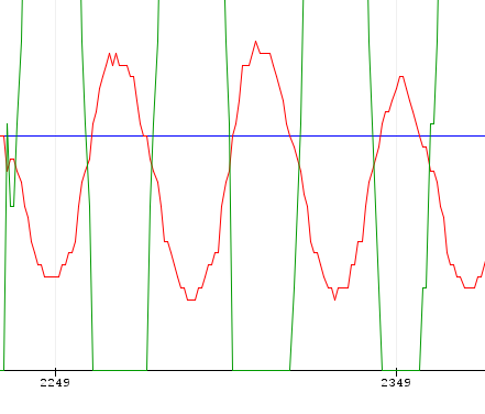
Step 2 was straightforward and I eventually obtained an oscillating system response, shown in the figure at left, with Kp=6.6.
第 2 步很简单,我最终获得了振荡系统响应,如左图所示,Kp=6.6。
This response curve is also the basis for the constants calculated in the Zeigler-Nichols method below. Between readings 2249 and 2239 (100 data points at 50ms each) on the x-axis are 2.5 oscillations, giving 5s for 2.5 oscillations, or 2s/osc.
该响应曲线也是下面 Zeigler-Nichols 方法中计算的常数的基础。x 轴上的读数 2249 和 2239(100 个数据点,每个数据点 50ms)之间是 2.5 次振荡,2.5 次振荡为 5 秒,即 2 秒/osc。

Step 3, increasing Td, yielded the graph at right when Td=0.4. Interesting to note at this stage that the PID converges to a stable response but is offset from the actual SP.
步骤3,增加Td,当Td=0.4时,得到右边的图形。有趣的是,在此阶段,PID 收敛到稳定的响应,但与实际 SP 有偏移。
In my case, iterating additional steps 2 & 3 yielded nothing, so I moved on to Step 4.
就我而言,迭代额外的步骤 2 和 3 没有任何结果,所以我继续执行第 4 步。

Step 4 concluded when I achieved an ‘acceptable’ response with Ti=1.2.
当我获得 Ti=1.2 的“可接受”响应时,第 4 步结束。
It is interesting to note that the CO line (green) is working very hard to maintain control. In a mechanical system (eg a physical valve actuating) this would cause excessive wear and would probably not be acceptable. In my case of an all-electric system running a fan motor, this is not a major issue.
有趣的是,一氧化碳线(绿色)正在努力保持控制。在机械系统(例如,物理阀门驱动)中,这会导致过度磨损,并且可能是不可接受的。在我运行风扇电机的全电动系统的情况下,这不是一个主要问题。
Finally, the fully controlled step response up (10 to 20) and down (20 to 10) are show in the figure below.
最后,完全受控的阶跃响应上升(10 至 20)和下降(20 至 10)如下图所示。

Heuristic A Kp=6.6 Ti=0.4 Td=1.2
启发式 A Kp=6.6 Ti=0.4 Td=1.2
Zeigler-Nichols Method Zeigler-Nichols方法
The Zeigler-Nicols method has been around since the 1940’s and is a popular heuristic PID tuning method, well described in the literature (see [2]). The ZN rules work well on processes where the dead time is less than half the length of the time constant.
Zeigler-Nicols 方法自 1940 年代以来一直存在,是一种流行的启发式 PID 调谐方法,在文献中有很好的描述(参见 [2])。ZN 规则适用于死区时间小于时间常数长度一半的过程。
The basic tuning steps are:
基本调优步骤如下:
- Set all gains to zero.
将所有增益设置为零。 - Increase the Kp until the response to a disturbance is steady oscillation. This is called the ‘ultimate’ gain Ku.
增加 Kp,直到对扰动的响应是稳定的振荡。这被称为“终极”增益 Ku。 - Measure the ‘ultimate’ oscillation period Tu at this steady state.
测量此稳态下的“极限”振荡周期 Tu。
Ku and Tu can then be used to calculate values for Kp, Ti and Td, depending on the type of control algorithm implemented, according to the table below (taken from [2]).
然后,可以使用 Ku 和 Tu 来计算 Kp、Ti 和 Td 的值,具体取决于实现的控制算法类型,如下表(摘自 [2])。
| Control Type 控制类型 | Kp | Ti | Td |
|---|---|---|---|
| P | 0.5Ku | – | – |
| PI | 0.45Ku | Tu/1.2 | – |
| PD | 0.8Ku | – | Tu/8 |
| Classic PID 经典 PID | 0.6Ku | Tu/2 | Tu/8 |
| Pessen Integral Rule 佩森积分法则 | 0.7Ku | Tu/2.5 | 3Tu/20 |
| Some overshoot 一些超调 | 0.33Ku | Tu/2 | Tu/3 |
| No overshoot 无过冲 | 0.2Ku | Tu/2 | Tu/3 |
Ku and Tu were determined in Step 2 in the previous method (Ku=6.6, Tu=2). Calculating it all out in a spreadsheet provides all the coefficients for the different test settings.
Ku 和 Tu 在前述方法的步骤 2 中测定 (Ku=6.6,Tu=2)。在电子表格中计算所有值可提供不同测试设置的所有系数。
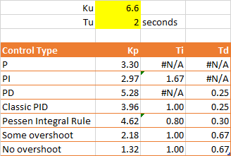
The charts obtained are shown below. The Classic and Pessen Integral Rule PID parameters performed the best in this situation. P was unacceptable due to the constant error from the SP (as expected). Neither of the ‘overshoot’ parameters worked to prevent overshoot but they damped the oscillations better than the pure PID parameters. I expect the overshoot is due to the characteristics of the equipment – it is really hard not to overshoot as the air pressure builds up under the ball. In all cases the control response could potentially be manually tuned further.
获得的图表如下所示。在这种情况下,Classic 和 Pessen 积分规则 PID 参数表现最佳。由于 SP 的持续误差(如预期的那样),P 是不可接受的。“过冲”参数都无法防止过冲,但与纯PID参数相比,它们更好地抑制了振荡。我预计超调是由于设备的特性造成的——随着球下方气压的增加,真的很难不超调。在所有情况下,控制响应都可能被手动进一步调整。
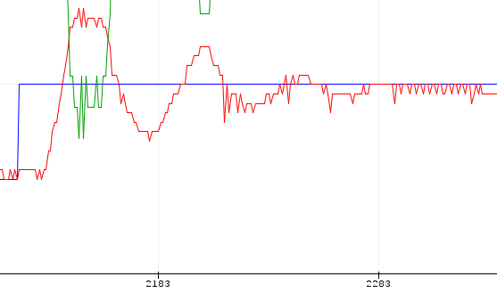 ZN P Kp=3.3 Ti=Td=0 ZN, P, Kp=3.3 Ti=Td=0

ZN PI Kp=2.97 Ti=1.67 Td=0
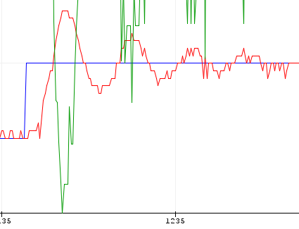 ZN PD Kp=5.28 Ti=0 Td=0.25

ZN Classic PID Kp=3.96 Ti=1.00 Td=0.25
ZN 经典 PID Kp=3.96 Ti=1.00 Td=0.25
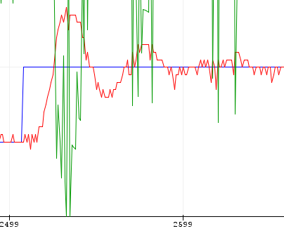 ZN Pessen Kp=4.62 Ti=0.80 Td=0.30
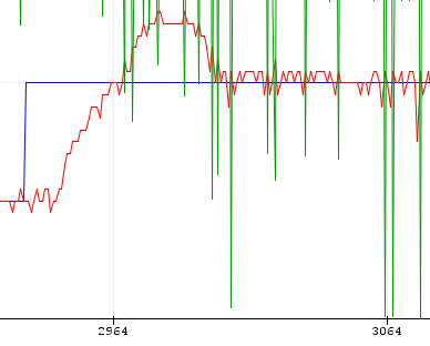 ZN Some Overshoot Kp=2.18 Ti=1.00 Td=0.67
ZN:一些过冲,Kp=2.18,Ti=1.00,Td=0.67
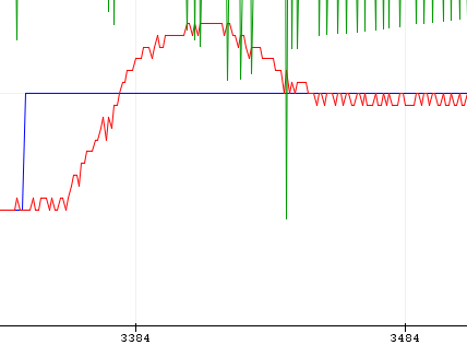 ZN No Overshoot Kp=1.32 Ti=1.00 Td=0.67
ZN 无超调 Kp=1.32 Ti=1.00 Td=0.67
Cohen-Coon Method Cohen-Coon 方法
Cohen-Coon tuning rules are second in popularity to the Ziegler-Nichols rules. Cohen and Coon published their method around a decade after Zeigler-Nichols, in the 1950’s. The CC rules work well on processes where the dead time is less than two times the length of the time constant.
Cohen-Coon 调谐规则的受欢迎程度仅次于 Ziegler-Nichols 规则。Cohen 和 Coon 在 Zeigler-Nichols 之后大约十年,即 1950 年代发表了他们的方法。CC 规则适用于死区时间小于时间常数长度两倍的进程。
The rules for this tuning method are given in [2]. It is far more involved that the ZN method as it requires measuring a process time constant.
[2] 中给出了这种调优方法的规则。它比 ZN 方法更复杂,因为它需要测量过程时间常数。
However, as the ball levitation exercise has a short dead time constant (shorter than the process time constant) there seems to be little to gain in trying this alternative method so I will leave this for another time.
然而,由于球悬浮练习的死区时间常数很短(比过程时间常数短),因此尝试这种替代方法似乎没有什么好处,所以我将把它留到另一个时间。
Conclusion 结论
I set out to find out how to tune a PID loop and achieved that aim.
我开始研究如何调整 PID 环路并实现了这个目标。
So which would I choose out of all the combinations tried? Heuristic A seems to give the most responsive settings for this equipment, followed by the ZN Classic and PIR parameters. In comparison to Heuristic A, all ZN parameters create less less extreme CO variation, which may be important in some applications.
那么,我会从所有尝试过的组合中选择哪一个呢?启发式 A 似乎为此设备提供了最灵敏的设置,其次是 ZN Classic 和 PIR 参数。与启发式 A 相比,所有 ZN 参数产生的 CO 变化较小,极端程度较小,这在某些应用中可能很重要。
References 引用
- Wikipedia https://en.wikipedia.org/wiki/PID_controller is a good overview of PID loops
Wikipedia https://en.wikipedia.org/wiki/PID_controller 很好地概述了 PID 回路 - Zeigler-Nichols Method at https://en.wikipedia.org/wiki/Ziegler-Nichols_method
Zeigler-Nichols 方法在 https://en.wikipedia.org/wiki/Ziegler-Nichols_method - “Cohen-Coon Tuning Rules” at http://blog.opticontrols.com/archives/383
http://blog.opticontrols.com/archives/383 中的“Cohen-Coon 调谐规则” - Tim Westcott, “PID without the PhD”, Embedded Systems Programming, October 2000 found at http://www.embedded.com/design/prototyping-and-development/4211211/PID-without-a-PhD
蒂姆·韦斯科特(Tim Westcott),“没有博士学位的PID”,《嵌入式系统编程》,2000年10月,在 http://www.embedded.com/design/prototyping-and-development/4211211/PID-without-a-PhD


