Micropython ESP32
- 模块列表
- network模块
- WIFI STA模式
- WIFI AP模式
- machine模块
- CPU主频
- GPIO端口
- GPIO输入模式
- GPIO输出模式
- GPIO中断模式
- ADC模数转换
- DAC数模转换
- PWM脉冲宽度调制
- UART串口
- Timer定时器
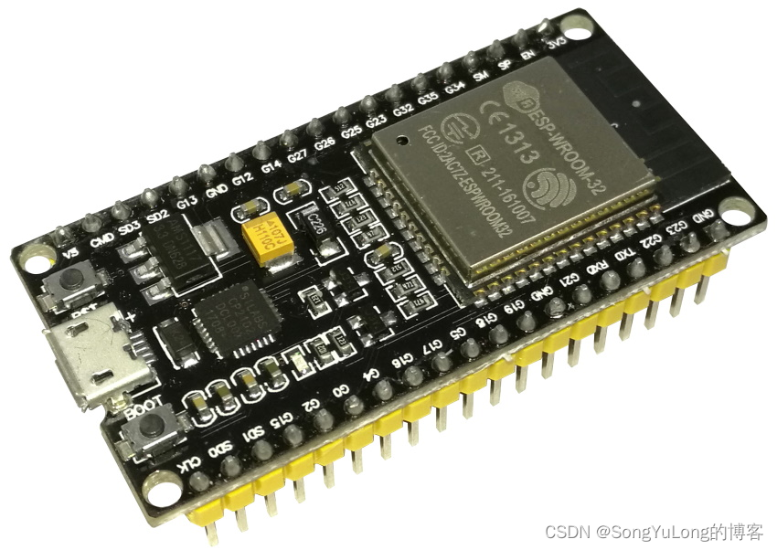
官方文档
下载固件
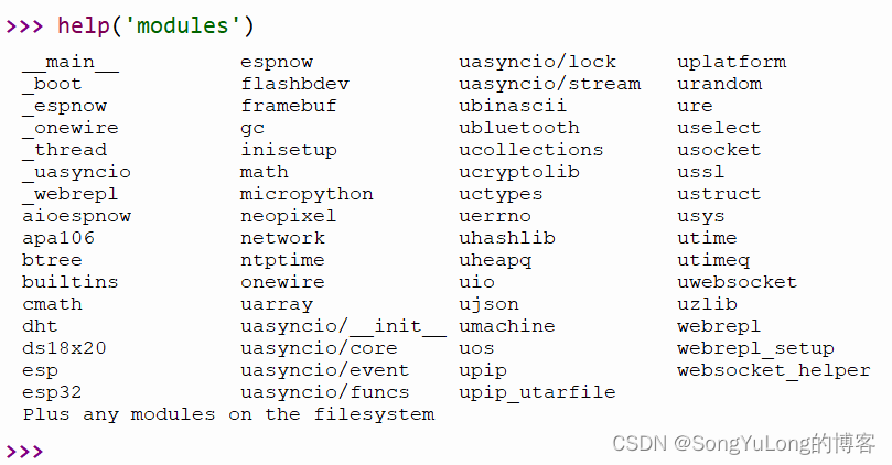
模块列表
network模块
help(network)
object <module ‘network’> is of type module
name – network
init –
WLAN –
LAN –
PPP –
phy_mode –
WIFI模式:
STA_IF – 0
AP_IF – 1
MODE_11B – 1
MODE_11G – 2
MODE_11N – 4
MODE_LR – 8
WIFI_PS_NONE – 0
WIFI_PS_MIN_MODEM – 1
WIFI_PS_MAX_MODEM – 2
WIFI加密认证方式:
AUTH_OPEN – 0
AUTH_WEP – 1
AUTH_WPA_PSK – 2
AUTH_WPA2_PSK – 3
AUTH_WPA_WPA2_PSK – 4
AUTH_WPA2_ENTERPRISE – 5
AUTH_WPA3_PSK – 6
AUTH_WPA2_WPA3_PSK – 7
AUTH_WAPI_PSK – 8
AUTH_MAX – 9
有线网络PHY支持类型:
PHY_LAN8720 – 0
PHY_IP101 – 1
PHY_RTL8201 – 2
PHY_DP83848 – 3
PHY_KSZ8041 – 4
有线网络状态:
ETH_INITIALIZED – 0
ETH_STARTED – 1
ETH_STOPPED – 2
ETH_CONNECTED – 3
ETH_DISCONNECTED – 4
ETH_GOT_IP – 5
WIFI状态:
STAT_IDLE – 1000
STAT_CONNECTING – 1001
STAT_GOT_IP – 1010
STAT_NO_AP_FOUND – 201
STAT_WRONG_PASSWORD – 202
STAT_BEACON_TIMEOUT – 200
STAT_ASSOC_FAIL – 203
STAT_HANDSHAKE_TIMEOUT – 204
help(network.WLAN())
object is of type WLAN
active –
connect –
disconnect –
status –
scan –
isconnected –
config –
ifconfig –
-
class network.WLAN(mode):
mode:模式
1)network.STA_IF 站点模式,连接WiFi路由器AP接入点
2)network.AP_IF 热点模式,作为WiFi AP热点(WiFi路由器)允许其它设备接入 -
wlan.active(is_active)
函数说明:带有参数时,为是否激活 WiFi,不带参数为查询当前状态。
is_active:是否激活,True:激活网络接口,False :停用网络接口。 -
wlan.scan():
函数说明:扫描可用的无线网络(仅在 STA 接口上进行扫描),返回有关 WiFi 接入点信息的元组列表(ssid,bssid,channel,RSSI,authmode,hidden):
bssid:接入点的硬件地址,以二进制形式返回为字节对象。
authmode:加密认证方式
hidden:是否可见,False 可见,True 隐藏 -
wlan.isconnected()
函数说明:检查站点是否连接到 AP。
在 STA 模式下,如果连接到 WiFi 接入点并具有有效的 IP 地址则返回 True,否则返回 False。
在 AP 模式下,当站点连接时返回 True,否则返回 False。 -
wlan.connect(essid, password)
函数说明:连接到无线网络。
essid:WiFi 名称
password:WiFi 密码 -
wlan.config(‘param’)
-
wlan.config(param=value,…)
函数说明: 获取接口的 MAC adddress 或者设置 WiFi 接入点名称和 WiFi 通道。
wlan.config(‘mac’)
ap.config(ssid=‘My AP’, channel=11)
print(ap.config(‘ssid’))
| Parameter | Description |
|---|---|
| mac | MAC address (bytes) |
| essid | WiFi access point name (string) |
| channel | WiFi channel (integer) |
| hidden | Whether SSID is hidden (boolean) |
| security | Security protocol supported (enumeration, see module constants) |
| key | Access key (string) |
| hostname | The hostname that will be sent to DHCP (STA interfaces) and mDNS (if supported, both STA and AP) |
| reconnects | Number of reconnect attempts to make (integer, 0=none, -1=unlimited) |
| txpower | Maximum transmit power in dBm (integer or float) |
-
wlan.ifconfig([(ip,mask, gateway, dns)])
函数说明:不带参数时,返回一个 4 元组 (ip, subnet_mask, gateway, DNS_server)。
ip:内网IP 地址
mask:子网掩码
gateway:网关
DNS_server: DNS服务器
带参数时,配置静态 IP。例如:
wlan.ifconfig(config = (‘192.168.0.4’, ‘255.255.255.0’, ‘192.168.0.1’, ‘8.8.8.8’)) -
wlan.disconnect()
函数说明:断开与当前连接的无线网络的连接。 -
wlan.status()
函数说明:返回无线连接的当前状态。
WIFI STA模式
import network
import utime

wlan = network.WLAN(network.STA_IF) # 创建station接口
wlan.active(True) # 激活接口
networks = wlan.scan() # 扫描可访问的热点

AUTHMODE = {0: "open", 1: "WEP", 2: "WPA-PSK", 3: "WPA2-PSK", 4: "WPA/WPA2-PSK"}
for ssid, bssid, channel, rssi, authmode, hidden in sorted(networks, key=lambda x: x[3], reverse=True):
    ssid = ssid.decode('utf-8')
    encrypted = authmode > 0
    print("ssid: %s chan: %d rssi: %d authmode: %s" % (ssid, channel, rssi, AUTHMODE.get(authmode, '?')))

if wlan.isconnected():
    print('is connected')
    wlan.disconnect()
else:
    print('not connected')

wlan.connect('testwifi', '88888888')
print(wlan.config('mac')) # 获取MAC地址
print(wlan.ifconfig()) # 获取接口IP地址/掩码/网关/DNS地址


while True:
    print(wlan.status())
    utime.sleep(10)
WIFI AP模式
import network
import utime

ap = network.WLAN(network.AP_IF)
ap.active(True)
ap.config(essid='esp32-ap', authmode=network.AUTH_WPA_WPA2_PSK, password='12345678')

print(ap.ifconfig())

while True:
    print(ap.status())
    utime.sleep(1)
machine模块
help(machine)
object <module ‘umachine’> is of type module
name – umachine
mem8 – <8-bit memory>
mem16 – <16-bit memory>
mem32 – <32-bit memory>
freq –
reset –
soft_reset –
unique_id –
sleep –
lightsleep –
deepsleep –
idle –
disable_irq –
enable_irq –
bitstream –
time_pulse_us –
Timer – <class ‘Timer’>
WDT – <class ‘WDT’>
SDCard – <class ‘SDCard’>
SLEEP – 2
DEEPSLEEP – 4
Pin – <class ‘Pin’>
Signal – <class ‘Signal’>
TouchPad – <class ‘TouchPad’>
ADC – <class ‘ADC’>
ADCBlock – <class ‘ADCBlock’>
DAC – <class ‘DAC’>
I2C – <class ‘I2C’>
SoftI2C – <class ‘SoftI2C’>
I2S – <class ‘I2S’>
PWM – <class ‘PWM’>
RTC – <class ‘RTC’>
SPI – <class ‘SPI’>
SoftSPI – <class ‘SoftSPI’>
UART – <class ‘UART’>
reset_cause –
HARD_RESET – 2
PWRON_RESET – 1
WDT_RESET – 3
DEEPSLEEP_RESET – 4
SOFT_RESET – 5
wake_reason –
PIN_WAKE – 2
EXT0_WAKE – 2
EXT1_WAKE – 3
TIMER_WAKE – 4
TOUCHPAD_WAKE – 5
ULP_WAKE – 6
CPU主频
machine.freq():无参返回当前CPU频率
machine.freq(freq):有参设置当前CPU频率
import machine
machine.freq(240000000) # 设置主频
cpufreq = machine.freq() # 获取主频
print(cpufreq)
GPIO端口
machine.Pin函数功能:
value():无参返回GPIO电平状态,有参设置GPIO电平状态
off():设置GPIO为低电平,相当于执行value(0)
on():设置GPIO为高电平,相当于执行value(1)
irq():设置GPIO中断函数
GPIO输入输出模式:
- IN – 1 :输入模式
- OUT – 3 :输出模式
- OPEN_DRAIN – 7 : 开漏模式
GPIO上下拉模式:
- PULL_UP – 2 : 上拉
- PULL_DOWN – 1 :下拉
- PULL_HOLD – 4 :深度休眠引脚电平保持
GPIO中断方式:
- IRQ_RISING – 1 :上升沿触发
- IRQ_FALLING – 2 :下降沿触发
GPIO唤醒电平
- WAKE_LOW – 4:低电平唤醒
- WAKE_HIGH – 5:高电平唤醒
GPIO输入模式
from machine import Pin
import utime

key = Pin(0, Pin.IN, Pin.PULL_UP)

while True:
    if key.value():
        print('KEY UP')
    else:
        print('KEY DOWN')
    utime.sleep(0.5)
GPIO输出模式
from machine import Pin
import utime

led = Pin(2, Pin.OUT, Pin.PULL_UP, drive=Pin.DRIVE_3)

print(led.value())
led.value(0)
led.value(1)

while True:
    led.on()
    utime.sleep(1)
    print(led.value())
    led.off()
    utime.sleep(1)
    print(led.value())
GPIO中断模式
irq(trigger, handler), trigger中断触发方式,handler中断处理函数
- 下降沿:trigger=machine.Pin.IRQ_FALLING
- 上升沿:trigger=machine.Pin.IRQ_RISING
import machine
from machine import Pin
import utime

led = Pin(2, Pin.OUT, drive=Pin.DRIVE_3)
key = Pin(0, Pin.IN, Pin.PULL_UP)

state = True
def irq_handler(pin):
    print(pin)
    global state
    state = not state
    if state :
        led.on()
    else:
        led.off()

key.irq(trigger=Pin.IRQ_RISING, handler=irq_handler)
# Pin.IRQ_FALLING 下降沿触发
# Pin.IRQ_RISING  上升沿触发

while True:
    print('ESP32 IRQ DEMO...')
    utime.sleep(1)
ADC模数转换
init –
block –
read():读取值范围0~4095
read_u16():读取值范围0~65535
read_uv(): 读取线性范围内微伏变化值
ADC.atten(atten) :设置输入衰减分贝值
ADC.width(width) : 设置ADC精度
ADC输入衰减:
要读取高于参考电压的电压,请使用atten关键字参数应用输入衰减。有效值(和近似的线性测量范围)为:
- ADC.ATTN_0DB :No attenuation (100mV - 950mV) ,默认值
- ADC.ATTN_2_5DB :2.5dB attenuation (100mV - 1250mV)
- ADC.ATTN_6DB :6dB attenuation (150mV - 1750mV)
- ADC.ATTN_11DB :11dB attenuation (150mV - 2450mV)
ADC分辨率:
- ADC.WIDTH_9BIT :9位精度
- ADC.WIDTH_10BIT :10位精度
- ADC.WIDTH_11BIT :11位精度
- ADC.WIDTH_12BIT :12为精度, 默认值
ADC测试例程:
from machine import ADC,Pin
import utime

adc = ADC(Pin(36))
adc.atten(ADC.ATTN_11DB)
adc.width(ADC.WIDTH_12BIT)

while True:
    val1 = adc.read()
    val2 = adc.read_u16()
    val3 = (int)(adc.read_uv()/1000)
    print(val1, val2, val3)
    utime.sleep(0.1)
DAC数模转换
2路8位DAC,DAC取值范围0~255,DAC引脚输出电压范围0 ~ 3.3V。
from machine import DAC, Pin

dac1 = DAC(Pin(25))
dac2 = DAC(Pin(26))

# DAC取值范围:0~255
dac1.write(0)
dac1.write(255)

dac2.write(128)
dac2.write(255)
PWM脉冲宽度调制
init –
PWM.deinit():关闭PWM
PWM.freq():无参返回当前PWM频率,有参设置PWM频率,频率范围1Hz~40MHz
PWM.duty(): 无参返回当前占空比,有参设置占空比,占空比范围0~1024
PWM.duty_u16:无参返回当前占空比,有参设置占空比,占空比范围0~65535
PWM.duty_ns:无参返回当前占空比,有参设置占空比,占空比范围0~1000000000/freq
from machine import Pin, PWM

pwm0 = PWM(Pin(0))         # create PWM object from a pin
freq = pwm0.freq()         # get current frequency (default 5kHz)
pwm0.freq(1000)            # set PWM frequency from 1Hz to 40MHz

duty = pwm0.duty()         # get current duty cycle, range 0-1023 (default 512, 50%)
pwm0.duty(256)             # set duty cycle from 0 to 1023 as a ratio duty/1023, (now 25%)

duty_u16 = pwm0.duty_u16() # get current duty cycle, range 0-65535
pwm0.duty_u16(2**16*3//4)  # set duty cycle from 0 to 65535 as a ratio duty_u16/65535, (now 75%)

duty_ns = pwm0.duty_ns()   # get current pulse width in ns
pwm0.duty_ns(250_000)      # set pulse width in nanoseconds from 0 to 1_000_000_000/freq, (now 25%)

pwm0.deinit()              # turn off PWM on the pin

pwm2 = PWM(Pin(2), freq=20000, duty=512)  # create and configure in one go
print(pwm2)                               # view PWM settings
UART串口
-
UART.deinit():
关闭串口 -
UART.any():
返回接收缓冲区数据个数
n = UART.any() -
UART.write(buf):
写入数据
buffer = b’hello world\r\n’
UART.write(buffer) -
UART.read(n):
读取n个数据
buffer = UART.read()
buffer = UART.read(5) -
UART.readline():
读取一行数据’\n’结束为一行
buffer = bytearray(100)
buffer = UART.readline() -
UART.readinto():
读取数据到指定buffer
buffer = bytearray(100)
UART.readinto(buffer)
UART.readinto(buffer, 10) #读取10个数据到buffer -
UART.sendbreak()
-
常量
INV_TX – 32
INV_RX – 4
INV_RTS – 64
INV_CTS – 8
RTS – 1
CTS – 2
串口例程
from machine import UART
import utime

uart1 = UART(1, baudrate=9600, tx=10, rx=9)
uart1.write('uart hello\r\n')  # write 5 bytes

buf = bytearray(10)
while True:
    m = uart1.any()
    print(m)
    if m:
        uart1.readinto(buf, 1)
        #buf = uart1.readline()
        print(buf)
        uart1.write(buf)
        #uart1.sendbreak()

    #uart1.read(5)         # read up to 5 bytes
    utime.sleep(1)
Timer定时器
-
Timer.deinit():
-
Timer.init(period, mode, callback):
初始化定时器
tim0 = Timer(0)
tim0.init(period=5000, mode=Timer.ONE_SHOT, callback=lambda t:print(0))
tim1 = Timer(1)
tim1.init(period=2000, mode=Timer.PERIODIC, callback=lambda t:print(1)) -
Timer.value()
-
Timer.ONE_SHOT – 0 : 执行一次
-
Timer.PERIODIC – 1 :周期性执行
from machine import Timer

def timer_func(tim):
    print('tim1 run', tim)
    pass

tim0 = Timer(0)
tim0.init(period=5000, mode=Timer.ONE_SHOT, callback=lambda t:print('timer 1 one shot'))

tim1 = Timer(1)
tim1.init(period=2000, mode=Timer.PERIODIC, callback=timer_func)


