一、组网需求
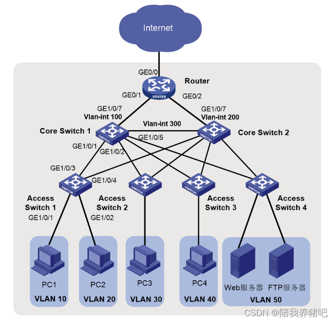
在中小园区中,S5130系列或S5130S系列以太网交换机通常部署在网络的接入层,S5560X系列或
S6520X系列以太网交换机通常部署在网络的核心,出口路由器一般选用MSR系列路由器。
- 核心交换机配置VRRP保证网络可靠性。
- 园区网中不同的业务部门划分到不同的VLAN中,部门间的业务在核心交换机上通过VLAN接口三层互通。
- 核心交换机作为DHCP服务器,为园区网用户分配IP地址。
- 接入交换机上配置DHCP Snooping功能,防止内网用户私接小路由器分配IP地址;同时配置IP Source Guard功能,防止内网用户私自更改IP地址。
- 在出口路由器上对双向流量配置基于IP的限速。
二、配置思路与数据规划
(1) 登录设备
(2) 配置管理IP地址和Telnet功能
(3) 配置网络互连互通
(4) 配置核心交换机DHCP功能
(5) 配置核心交换机OSPF功能
(6) 配置核心交换可靠性功能
(7) 配置限速
配置数据表
| 配置步骤 | 配置项 | 配置数据 | 说明 |
| 登录设备 | 通过Console口登录 | 设置传输速率等通信参数 | PC端通过终端仿真软件登录设备 |
| 配置管理IP和telnet功能 | 管理VLAN | VLAN 5 | 交换机缺省VLAN为VLAN 1。一般不将其配置为管理VLAN 本文将VLAN5配置为管理VLAN |
| 管理用以太网口或管理VLAN接口IP地址 | 10.10.1.1/24 | 此处以ACCSW1为例。 有管理用以太网口的交换机,可为管理用以太网口M-GigabitEthernet0/0/0配置IP地址用于登录交换机。 没有管理用以太网口的交换机,可为管理VLAN接口配置IP地址。 | |
| 配置接口和VLAN | 端口类型 | 连接交换机的端口建议设置为trunk,连接PC的端口设置为access。 | trunk类型端口一般用于连接交换机。 access类型端口一般用于连接PC。 hybrid类型端口是通用端口,既可以用来连接交换机,也可用来连接PC。 |
| VLAN ID | ACCSW1:VLAN 10、20 CORESW1:VLAN 10、20、30、40、50、100、300 | 为实现部门A和部门B二层隔离,将部门A划分到VLAN10中,部门B划分到VLAN20中。 核心交换机1通过Vlan-int100连接出口路由器 | |
| 核心交换机上配置DHCP服务器功能 | DHCP Server | CORESW1、CORESW2 | 在核心交换机1、核心交换机2上部署DHCPServer |
| 地址池 | VLAN 10:ip pool 10 VLAN 20:ip pool 20 | 部门A的终端从ip pool 10中获取IP地址 部门B的终端从ip pool 20中获取IP地址 | |
| 地址分配方式 | 基于全局地址池 | 无 | |
| 配置核心交换机路由 | IP地址 | 以CORESW1为例: Vlan-int10:192.168.10.1/24 Vlan-int20:192.168.20.1/24 Vlan-int100:172.16.1.1/24 Vlan-int300:172.16.3.1/24 | Vlan-int100用于核心交换机1与园区出口路由器对接。Vlan-int300用于核心交换机1与核心交换机2对接 在核心交换机1上配置Vlan-int10、Vlan-int20的IP地址后,部门A与部门B之间可以通过核心交换机1互访 |
| 配置出口路由器 | 公网接口的IP地址 | GE0/0:202.101.100.2/30 | GE0/0为出口路由器连接Internet的接口,一般称为公网接口 |
| 公网网关 | 202.101.100.1/30 | 该地址是与出口路由器对接的运营商设备的IP地址,出口路由器上需要配置一条缺省路由指向该地址,用于指导内网流量转发至Internet | |
| DNS地址 | 202.101.100.199 | DNS服务器用于将域名解析成IP地址 | |
| 内网接口的IP地址 | GE0/1:172.16.1.2/24 GE0/2:172.16.2.2/24 | GE0/1、GE0/2为出口路由器连接内网的接口,GE0/1连接主设备,GE0/2连接备设备 | |
| 在接入交换机上配置DHCP Snooping和IP Source Guard | 信任接口 | GE1/0/1 GE1/0/2 | 配置信任接口后,用户只会接收从信任接口进入的DHCP报文,防止内网私接小路由器为主机分配IP地址 |
三、配置步骤
3.1 配置接入交换机
PS:接入交换机ACCSW1、ACCSW2、ACCSW3和ACCSW4的配置基本相同。本文以配置接入
交换机ACCSW1为例说明配置方法。
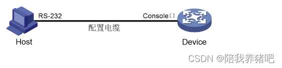
3.1.1 通过Console口首次登录设备
# 将PC断电。
因为PC的串口不支持热插拔,请不要在PC带电的情况下,将串口线插入或者拔出PC。
# 使用产品随机附带的配置口电缆连接PC机和设备。请先将配置口电缆的DB-9(孔)插头插入PC
机的9芯(针)串口中,再将RJ-45插头端插入设备的Console口中。
将设备与PC通过配置口电缆进行连接。
# 给PC上电。
# 在PC上打开终端仿真程序,按照要求设置终端参数。
终端参数设置:
| 参数 | 值 |
| 波特率 | 9600 |
| 数据位 | 8 |
| 停止位 | 1 |
| 奇偶校验 | 无 |
| 流量控制 | 无 |
# 给设备上电。
在设备自检结束后,用户可键入回车进入命令交互界面。
PS:缺省情况下,通过Console登录设备的认证方式为None,即不需要用户名、密码即可登录设
备。首次登录后,建议修改通过Console口登录设备的认证方式以增强设备的安全性。
3.1.2 配置IP地址和Telnet
# 创建VLAN 5,并将接口Ten-GigabitEthernet1/0/10加入到VLAN 5中。假设连接网管的接口是
Ten-GigabitEthernet1/0/10。
<Sysname> system-view
System View: return to User View with Ctrl+Z.
[Sysname] sysname ACCSW1
[ACCSW1] vlan 5
[ACCSW1-vlan5] port ten-gigabitethernet 1/0/10
[ACCSW1-vlan5] quit
# 创建VLAN接口5,并将接口IP地址配置为10.10.1.1/24。
[ACCSW1] interface vlan-interface 5
[ACCSW1-Vlan-interface5] ip address 10.10.1.1 24
[ACCSW1-Vlan-interface5] quit
# 开启Telnet服务 。
[ACCSW1] telnet server enable# 配置Telnet登录使用scheme认证方式。
[ACCSW1] line vty 0 63
[ACCSW1-line-vty0-63] authentication-mode scheme
[ACCSW1-line-vty0-63] quit
# 创建本地用户,并配置本地用户的密码、用户角色和服务类型。本例中用户名和密码均为
admin,服务类型为telnet,用户角色为network-admin。
[ACCSW1] local-user admin
New local user added.
[ACCSW1-luser-manage-admin] password simple hello12345
[ACCSW1-luser-manage-admin] authorization-attribute user-role network-admin
[ACCSW1-luser-manage-admin] service-type telnet
[ACCSW1-luser-manage-admin] quit
# 在终端上通过Telnet登录到设备,输入正确的用户名和密码后,出现用户视图的命令行提示符表
示登录成功。
C:\Users\Administrator> telnet 10.10.1.1
******************************************************************************
* Copyright (c) 2004-2019 New H3C Technologies Co., Ltd. All rights reserved.*
* Without the owner's prior written consent,                                 *
* no decompiling or reverse-engineering shall be allowed.                    *
******************************************************************************

login: admin
Password:
...
PS:上述终端输出信息是以S5560X-30C-PWR-EI设备(Release 1118P07版本)为例。
3.1.3 配置接口与VLAN
# 在接入交换机上创建VLAN 10和VLAN 20。
[ACCSW1] vlan 10 20# 将连接PC1的接口GigabitEthernet1/0/1加入VLAN 10,并配置为边缘端口。
[ACCSW1] interface gigabitethernet 1/0/1
[ACCSW1-GigabitEthernet1/0/1] port link-type access
[ACCSW1-GigabitEthernet1/0/1] port acess vlan 10
[ACCSW1-GigabitEthernet1/0/1] stp edged-port
[ACCSW1-GigabitEthernet1/0/1] quit
# 将连接PC1的接口GigabitEthernet1/0/2加入VLAN 20,并配置为边缘端口。
[ACCSW1] interface gigabitethernet 1/0/2
[ACCSW1-GigabitEthernet1/0/2] port link-type access
[ACCSW1-GigabitEthernet1/0/2] port acess vlan 20
[ACCSW1-GigabitEthernet1/0/2] stp edged-port
[ACCSW1-GigabitEthernet1/0/2] quit
# 将接口GigabitEthernet1/0/3和GigabitEthernet1/0/4的链路类型配置为Trunk并允许VLAN 10和
VLAN 20的报文通过。
[ACCSW1] interface gigabitethernet 1/0/3
[ACCSW1-GigabitEthernet1/0/3] port link-type trunk
[ACCSW1-GigabitEthernet1/0/3] port trunk permit vlan 10 20
[ACCSW1-GigabitEthernet1/0/3] quit
[ACCSW1] interface gigabitethernet 1/0/4
[ACCSW1-GigabitEthernet1/0/4] port link-type trunk
[ACCSW1-GigabitEthernet1/0/4] port trunk permit vlan 10 20
[ACCSW1-GigabitEthernet1/0/4] quit
# 查看ACCSW1上VLAN 10和VLAN 20的配置信息。
[ACCSW1] display vlan 10
 VLAN ID: 10
 VLAN type: Static
 Route interface: Not configured
 Description: VLAN 0010
 Name: VLAN 0010
 Tagged ports:
    GigabitEthernet1/0/3
    GigabitEthernet1/0/4
 Untagged ports:
    GigabitEthernet1/0/1

[ACCSW1] display vlan 20
 VLAN ID: 20
 VLAN type: Static
 Route interface: Not configured
 Description: VLAN 0020
 Name: VLAN 0020
 Tagged ports:
    GigabitEthernet1/0/3
    GigabitEthernet1/0/4
 Untagged ports:
    GigabitEthernet1/0/2
3.1.4 配置BPDU保护功能
[ACCSW1] stp bpdu-protection3.1.5 配置DHCP snooping
# 开启DHCP Snooping功能。
[ACCSW1] dhcp snooping enable# 指定GigabitEthernet1/0/3为DHCP Snooping功能的信任端口。
[ACCSW1] interface gigabitethernet 1/0/3

[ACCSW1-GigabitEthernet1/0/3] dhcp snooping trust

[ACCSW1-GigabitEthernet1/0/3] quit
3.1.6 配置IP Source Guard
# 开启接口GigabitEthernet1/0/1、GigabitEthernet1/0/2的IPv4接口绑定功能,绑定源IP地址和
MAC地址,并启用接口的DHCP Snooping 表项记录功能。
[ACCSW1] interface gigabitethernet 1/0/1
[ACCSW1-GigabitEthernet1/0/1] ip verify source ip-address mac-address
[ACCSW1-GigabitEthernet1/0/1] dhcp snooping binding record
[ACCSW1-GigabitEthernet1/0/1] quit
[ACCSW1] interface gigabitethernet 1/0/2
[ACCSW1-GigabitEthernet1/0/2] ip verify source ip-address mac-address
[ACCSW1-GigabitEthernet1/0/2] dhcp snooping binding record
[ACCSW1-GigabitEthernet1/0/2] quit
3.1.7 保存配置
# 保存接入交换机上的配置(以ACCSW1为例)。
[ACCSW1] save
The current configuration will be written to the device. Are you sure? [Y/N]:y
Please input the file name(*.cfg)[flash:/startup.cfg]
(To leave the existing filename unchanged, press the enter key):
flash:/startup.cfg exists, overwrite? [Y/N]:y
Validating file. Please wait...
Saved the current configuration to mainboard device successfully.
3.2 配置核心交换机
PS:核心交换机CORESW1和CORESW2的配置基本相同。本文如无特殊说明,以配置核心交
换机CORESW1为例说明配置方法。
3.2.1 配置接口与VLAN
# 创建VLAN 10、VLAN 20、VLAN 30、VLAN 40、VLAN 50、VLAN 100和VLAN 300。
<Sysname> system-view
[Sysname] sysname CORESW1
[CORESW1] vlan 10 20 30 40 50 100 300
# 配置接口GigabitEthernet1/0/1的链路类型为Trunk,并允许VLAN 10和20的报文通过。
[CORESW1] interface gigabitethernet 1/0/1
[CORESW1-GigabitEthernet1/0/1] port link-type trunk
[CORESW1-GigabitEthernet1/0/1] port trunk permit vlan 10 20
[CORESW1-GigabitEthernet1/0/1] quit
# 配置接口GigabitEthernet1/0/5的链路类型为Trunk,并允许VLAN 300的报文通过。
[CORESW1] interface gigabitethernet 1/0/5
[CORESW1-GigabitEthernet1/0/5] port link-type trunk
[CORESW1-GigabitEthernet1/0/5] port trunk permit vlan 300
[CORESW1-GigabitEthernet1/0/5] quit
# 配置其他接口的链路类型并允许对应的VLAN通过,具体配置过程略。
3.2.2 配置VLAN接口
# 创建VLAN接口10,并将接口的IP地址配置为192.168.10.1/24。
[CORESW1] interface vlan-interface 10
[CORESW1-Vlan-interface10] ip address 192.168.10.1 24
[CORESW1-Vlan-interface10] quit
# 创建VLAN接口20,并将接口的IP地址配置为192.168.20.1/24。
[CORESW1] interface vlan-interface 20
[CORESW1-Vlan-interface20] ip address 192.168.20.1 24
[CORESW1-Vlan-interface20] quit
# 创建VLAN接口100,并将接口的IP地址配置为172.16.1.1/24。
[CORESW1] interface vlan-interface 100
[CORESW1-Vlan-interface100] ip address 172.16.1.1 24
[CORESW1-Vlan-interface100] quit
# 创建VLAN接口300,并将接口的IP地址配置为172.16.3.1/24。
[CORESW1] interface vlan-interface 300
[CORESW1-Vlan-interface300] ip address 172.16.3.1 24
[CORESW1-Vlan-interface300] quit
# 创建其他VLAN接口,并配置IP地址,具体配置过程略。
# 查看CORESW1上VLAN 10、VLAN 20、VLAN 100、VLAN 300的配置信息。
[CORESW1] display vlan 10
 VLAN ID: 10
 VLAN type: Static
 Route interface: Configured
 IPv4 address: 192.168.10.1
 IPv4 subnet mask: 255.255.255.0
 Description: VLAN 0010
 Name: VLAN 0010
 Tagged ports:
    GigabitEthernet1/0/1
 Untagged ports:   None

[CORESW1] display vlan 20
 VLAN ID: 20
 VLAN type: Static
 Route interface: Configured
 IPv4 address: 192.168.20.1
 IPv4 subnet mask: 255.255.255.0
 Description: VLAN 0020
 Name: VLAN 0020
 Tagged ports:
    GigabitEthernet1/0/2
 Untagged ports:   None

[CORESW1] display vlan 100
 VLAN ID: 100
 VLAN type: Static
 Route interface: Configured
 IPv4 address: 172.16.1.1
 IPv4 subnet mask: 255.255.255.0
 Description: VLAN 0100
 Name: VLAN 0100
 Tagged ports:   None
 Untagged ports:   None

[CORESW1] display vlan 300
 VLAN ID: 300
 VLAN type: Static
 Route interface: Configured
 IPv4 address: 172.16.3.1
 IPv4 subnet mask: 255.255.255.0
 Description: VLAN 0300
 Name: VLAN 0300
 Tagged ports:
    GigabitEthernet1/0/5
 Untagged ports:   None
3.2.3 配置VRRP备份
正常情况下内网用户流量都上送到CORESW1进行处理,只有当CORESW1或CORESW1的上行
链路出故障之后,VRRP备份组切换CORESW2为主设备,内网用户流量上送到CORESW2。
# 在CORESW1上配置VRRP备份组功能。
# 创建VRRP备份组1,并配置VRRP备份组1的虚拟IP地址为172.16.3.10。
[CORESW1] interface vlan-interface 300
[CORESW1-Vlan-interface300] vrrp vrid 1 virtual-ip 172.16.3.10
# 设置CORESW1在VRRP备份组1中的优先级为120,高于CORESW2的优先级100,以保证
CORESW1成为Master负责转发流量。
[CORESW1-Vlan-interface300] vrrp vrid 1 priority 120# 设置CORESW1工作在抢占方式,以保证CORESW1故障恢复后,能再次抢占成为Master,即只
要CORESW1正常工作,就由CORESW1负责转发流量。为了避免频繁地进行状态切换,配置抢占
延迟时间为5000厘秒。
[CORESW1-Vlan-interface300] vrrp vrid 1 preempt-mode delay 5000
[CORESW1-Vlan-interface300] quit
# 创建和上行接口GigabitEthernet1/0/7物理状态关联的Track项1。如果Track项的状态为
Negative,则说明CORESW1的上行接口出现故障。
[CORESW1] track 1 interface gigabitethernet 1/0/7
[CORESW1-track-1] quit
# 设置监视Track项。
[CORESW1] interface vlan-interface 300
[CORESW1-Vlan-interface300] vrrp vrid 1 track 1 priority reduced 30
# 在CORESW2上配置VRRP备份组功能。创建VRRP备份组1,并配置VRRP备份组1的虚拟IP地
址为172.16.3.10。
<Sysname> system-view
[Sysname] sysname CORESW2
[CORESW2] interface vlan-interface 300
[CORESW2-Vlan-interface300] vrrp vrid 1 virtual-ip 172.16.3.10
# 配置CORESW2在VRRP备份组1中的优先级为100。
[CORESW2-Vlan-interface300] vrrp vrid 1 priority 100# 配置CORESW2工作在抢占方式,抢占延迟时间为5000厘秒。
[CORESW2-Vlan-interface300] vrrp vrid 1 preempt-mode delay 5000
[CORESW2-Vlan-interface300] quit
# 在CORESW1上使用display vrrp verbose命令查询VRRP备份组信息。
[CORESW1] display vrrp verbose
IPv4 Virtual Router Information:
 Running mode : Standard
 Total number of virtual routers : 1
   Interface Vlan-interface300
     VRID             : 1                   Adver Timer  : 100
     Admin Status     : Up                  State        : Master
     Config Pri       : 120                 Running Pri  : 120
     Preempt Mode     : Yes                 Delay Time   : 5000
     Auth Type        : None
     Virtual IP       : 172.16.3.10
     Virtual MAC      : 0000-5e00-0101
     Master IP        : 172.16.3.1
   VRRP Track Information:
     Track Object   : 1                   State : Positive   Pri Reduced : 30
# 在CORESW2上使用display vrrp verbose命令查询VRRP备份组信息。
[CORESW2] display vrrp verbose
IPv4 Virtual Router Information:
 Running mode : Standard
 Total number of virtual routers : 1
   Interface Vlan-interface300
     VRID             : 1                   Adver Timer  : 100
     Admin Status     : Up                  State        : Backup
     Config Pri       : 100                 Running Pri  : 100
     Preempt Mode     : Yes                 Delay Time   : 5000
     Become Master    : 27810ms left
     Auth Type        : None
     Virtual IP       : 172.16.3.10
     Virtual MAC      : 0000-5e00-0101
     Master IP        : 172.16.3.1
# 由此可见,VRRP备份组创建成功,CORESW1为Master设备,CORESW2为Backup设备。
3.2.4 配置DHCP服务器,并查看配置
# 开启DHCP服务。
[CORESW1] dhcp enable# 创建DHCP地址池1,用来为192.168.10.0/24网段内的客户端分配动态IP地址,并配置DNS服务
器地址、出口网关、租期,为打印机配置固定的IP地址192.168.10.254。
[CORESW1] dhcp server ip-pool 1
[CORESW1-dhcp-pool-1] network 192.168.10.0 mask 255.255.255.0
[CORESW1-dhcp-pool-1] gateway-list 192.168.10.1
[CORESW1-dhcp-pool-1] dns-list 202.101.100.199
[CORESW1-dhcp-pool-1] expired day 30
[CORESW1-dhcp-pool-1] static-bind ip-address 192.168.10.254 24 client-identifier aabb-cccc-dd
[CORESW1-dhcp-pool-1] quit
# 创建DHCP地址池2,用来为192.168.20.0/24网段内的客户端分配动态IP地址,并配置DNS服务
器地址、出口网关、租期。
[CORESW1] dhcp server ip-pool 2
[CORESW1-dhcp-pool-2] network 192.168.20.0 mask 255.255.255.0
[CORESW1-dhcp-pool-2] gateway-list 192.168.20.1
[CORESW1-dhcp-pool-2] dns-list 202.101.100.199
[CORESW1-dhcp-pool-2] expired day 30
[CORESW1-dhcp-pool-2] quit
# 配置VLAN接口10和VLAN接口20工作在DHCP服务器模式。
[CORESW1] interface vlan-interface 10
[CORESW1-Vlan-interface10] dhcp select server
[CORESW1-Vlan-interface10] quit
[CORESW1 interface vlan-interface 20
[CORESW1-Vlan-interface20] dhcp select server
[CORESW1-Vlan-interface20] quit
# 使用display dhcp server pool命令查看DHCP地址池的信息。
[CORESW1] display dhcp server pool
Pool name: 1
  Network: 192.168.10.0 mask 255.255.255.0
  expired 30 0 0 0
  gateway-list 192.168.10.1
  static bindings:
    ip-address 192.168.10.254 mask 255.255.255.0
      client-identifier aabb-cccc-dd
Pool name: 2
  Network: 192.168.20.0 mask 255.255.255.0
  expired 30 0 0 0
  gateway-list 192.168.20.1
3.2.5 配置OSPF
CORESW1的OSPF配置。
[CORESW1] ospf 100 router-id 2.2.2.2
[CORESW1-ospf-100] area 0
[CORESW1-ospf-100-area-0.0.0.0] network 172.16.1.0 0.0.0.255
[CORESW1-ospf-100-area-0.0.0.0] network 172.16.3.0 0.0.0.255
[CORESW1-ospf-100-area-0.0.0.0] network 192.168.10.0 0.0.0.255
[CORESW1-ospf-100-area-0.0.0.0] network 192.168.20.0 0.0.0.255
[CORESW1-ospf-100-area-0.0.0.0] quit
[CORESW1-ospf-100] quit
CORESW2的OSPF配置。
[CORESW2] ospf 100 router-id 3.3.3.3
[CORESW2-ospf-100] area 0
[CORESW2-ospf-100-area-0.0.0.0] network 172.16.2.0 0.0.0.255
[CORESW2-ospf-100-area-0.0.0.0] network 172.16.3.0 0.0.0.255
[CORESW2-ospf-100-area-0.0.0.0] network 192.168.10.0 0.0.0.255
[CORESW2-ospf-100-area-0.0.0.0] network 192.168.20.0 0.0.0.255
[CORESW2-ospf-100-area-0.0.0.0] quit
[CORESW2-ospf-100] quit
# 使用display ospf peer命令查看CORESW1上的OSPF邻居信息。
[CORESW1] display ospf peer

         OSPF Process 100 with Router ID 2.2.2.2
               Neighbor Brief Information

 Area: 0.0.0.0
 Router ID       Address         Pri Dead-Time  State             Interface
 3.3.3.3         172.16.3.2      1   33         Full/DR           Vlan300
# 使用display ospf peer命令查看CORESW2上的OSPF邻居信息。
[CORESW2] display ospf peer

         OSPF Process 100 with Router ID 3.3.3.3
               Neighbor Brief Information

 Area: 0.0.0.0
 Router ID       Address         Pri Dead-Time  State             Interface
 2.2.2.2         172.16.3.1      1   36         Full/BDR          Vlan300
3.2.6 保存配置
# 保存核心交换机上的配置(以CORESW1为例)。
[CORESW1] save
The current configuration will be written to the device. Are you sure? [Y/N]:y
Please input the file name(*.cfg)[flash:/startup.cfg]
(To leave the existing filename unchanged, press the enter key):
flash:/startup.cfg exists, overwrite? [Y/N]:y
Validating file. Please wait...
Saved the current configuration to mainboard device successfully.
3.3 配置出口路由器
3.3.1 配置内网接口和公网接口IP
# 配置内网接口IP地址。
[Router] interface GigabitEthernet 0/1
[Router-GigabitEthernet0/1] ip address 172.16.1.2 24
[Router-GigabitEthernet0/1] quit
[Router] interface GigabitEthernet 0/2
[Router-GigabitEthernet0/2] ip address 172.16.2.2 24
[Router-GigabitEthernet0/2] quit
# 配置公网接口IP地址。
[Router] interface GigabitEthernet 0/0
[Router-GigabitEthernet0/0] ip address 202.101.100.2 30
[Router-GigabitEthernet0/0] quit
3.3.2 配置允许上网的ACL
# 配置ACL。
[Router] acl basic 2000
[Router-acl-ipv4-basic-2000] rule permit source 192.168.10.0 0.0.0.255
[Router-acl-ipv4-basic-2000] rule permit source 192.168.20.0 0.0.0.255
[Router-acl-ipv4-basic-2000] rule permit source 172.16.1.0 0.0.0.255
[Router-acl-ipv4-basic-2000] rule permit source 172.16.2.0 0.0.0.255
[Router-acl-ipv4-basic-2000] rule permit source 172.16.3.0 0.0.0.255
[Router-acl-ipv4-basic-2000] quit
# 配置报文过滤。
[Router] interface gigabitethernet 0/1
[Router-GigabitEthernet0/1] packet-filter 2000 inbound
[Router-GigabitEthernet0/1] quit
[Router] interface gigabitethernet 0/2
[Router-GigabitEthernet0/2] packet-filter 2000 inbound
[Router-GigabitEthernet0/2] quit
[Router] packet-filter default deny
# 使用display acl命令查看ACL的配置信息。
[Router] display acl 200
Basic IPv4 ACL 2000, 5 rules,
ACL's step is 5, start ID is 0
 rule 0 permit source 192.168.10.0 0.0.0.255
 rule 5 permit source 192.168.20.0 0.0.0.255
 rule 10 permit source 172.16.1.0 0.0.0.255
 rule 15 permit source 172.16.2.0 0.0.0.255
 rule 20 permit source 172.16.3.0 0.0.0.255
# 使用display packet-filter命令查看ACL在报文过滤中的应用情况。
[Router] display packet-filter interface gigabitethernet 0/1 inbound
Interface: GigabitEthernet0/1
 Inbound policy:
  IPv4 ACL 2000

[Router] display packet-filter interface gigabitethernet 0/2 inbound
Interface: GigabitEthernet0/2
 Inbound policy:
  IPv4 ACL 2000
3.3.3 配置OSPF
配置一条缺省路由指向运营商。
[Router] ip route-static 0.0.0.0 0.0.0.0 202.101.100.1出口路由器的OSPF配置。在OSPF中引入缺省路由,从而连接内网和公网。
[Router] ospf 10 router-id 1.1.1.1
[Router-ospf-10] default-route-advertise always
[Router-ospf-10] area 0
[Router-ospf-10-area-0.0.0.0] network 172.16.1.0 0.0.0.255
[Router-ospf-10-area-0.0.0.0] network 172.16.2.0 0.0.0.255
[Router-ospf-10-area-0.0.0.0] quit
[Router-ospf-10] quit
# 使用display ospf peer命令查看Router上的OSPF邻居信息。
[Router] display ospf peer

         OSPF Process 100 with Router ID 1.1.1.1
               Neighbor Brief Information

 Area: 0.0.0.0
 Router ID       Address         Pri Dead-Time  State             Interface
 2.2.2.2         172.16.1.1      1   31         Full/DR           GE0/1
 3.3.3.3         172.16.2.1      1   39         Full/BDR          GE0/2
# 使用display ospf routing命令查看CORESW1上的OSPF路由表信息。
[CORESW1] display ospf routing

         OSPF Process 100 with Router ID 2.2.2.2
                  Routing Table

                Topology base (MTID 0)

 Routing for network
 Destination        Cost     Type    NextHop         AdvRouter       Area
 172.16.1.0/24      1        Transit 0.0.0.0         2.2.2.2         0.0.0.0
 172.16.2.0/24      2        Transit 172.16.3.2      1.1.1.1         0.0.0.0
 172.16.2.0/24      2        Transit 172.16.1.2      1.1.1.1         0.0.0.0
 172.16.3.0/24      1        Transit 0.0.0.0         3.3.3.3         0.0.0.0


 Routing for ASEs
 Destination        Cost     Type    Tag         NextHop         AdvRouter
 0.0.0.0/0          1        Type2   1           172.16.1.2      1.1.1.1


 Total nets: 5
 Intra area: 4  Inter area: 0  ASE: 1  NSSA: 0
# 使用display ospf routing命令查看CORESW2上的OSPF路由表信息。
[CORESW2] display ospf routing

         OSPF Process 100 with Router ID 3.3.3.3
                  Routing Table

                Topology base (MTID 0)


 Routing for network
 Destination        Cost     Type    NextHop         AdvRouter       Area
 172.16.1.0/24      2        Transit 172.16.3.1      2.2.2.2         0.0.0.0
 172.16.1.0/24      2        Transit 172.16.2.2      2.2.2.2         0.0.0.0
 172.16.2.0/24      1        Transit 0.0.0.0         1.1.1.1         0.0.0.0
 172.16.3.0/24      1        Transit 0.0.0.0         3.3.3.3         0.0.0.0


 Routing for ASEs
 Destination        Cost     Type    Tag         NextHop         AdvRouter
 0.0.0.0/0          1        Type2   1           172.16.2.2      1.1.1.1


 Total nets: 5
 Intra area: 4  Inter area: 0  ASE: 1  NSSA: 0
3.3.4 配置DNS解析
[Router] dns server 202.101.100.199
[Router] dns proxy enable
3.3.5 配置基于IP或IP网段的限速
# 配置CAR列表。
[Router] qos carl 1 source-ip-address range 192.168.10.1 to 192.168.10.254 per-address shared-bandwidth
[Router] qos carl 2 source-ip-address range 192.168.20.1 to 192.168.20.254 per-address shared-bandwidth
[Router] qos carl 3 destination-ip-address range 192.168.10.1 to 192.168.10.254 per-address shared-bandwidth
[Router] qos carl 4 destination-ip-address range 192.168.20.1 to 192.168.20.254 per-address shared-bandwidth
# 配置限速。
[Router] interface gigabitethernet 0/1
[Router-GigabitEthernet0/1] qos car inbound carl 1 cir 512
[Router-GigabitEthernet0/1] qos car inbound carl 2 cir 512
[Router-GigabitEthernet0/1] qos car outbound carl 3 cir 512
[Router-GigabitEthernet0/1] qos car outbound carl 4 cir 512
[Router-GigabitEthernet0/1] quit
[Router] interface gigabitethernet 0/2
[Router-GigabitEthernet0/2] qos car inbound carl 1 cir 512
[Router-GigabitEthernet0/2] qos car inbound carl 2 cir 512
[Router-GigabitEthernet0/2] qos car outbound carl 3 cir 512
[Router-GigabitEthernet0/2] qos car outbound carl 4 cir 512
[Router-GigabitEthernet0/2] quit
# 使用display qos carl命令查看CAR列表。
[Router] display qos carl
List  Rules
1     source-ip-address range 192.168.10.1 to 192.168.10.254 per-address shared-bandwidth
2     source-ip-address range 192.168.20.1 to 192.168.20.254 per-address shared-bandwidth
3     destination-ip-address range 192.168.10.1 to 192.168.10.254 per-address shared-bandwidth
4     destination-ip-address range 192.168.20.1 to 192.168.20.254 per-address shared-bandwidth
# 使用display qos car interface命令查看接口的流量监管配置情况和统计信息。
[Router] display qos car interface gigabitethernet 0/1
Interface: GigabitEthernet0/1
 Direction: inbound
  Rule: If-match carl 1
   CIR 512 (kbps), CBS 32000 (Bytes), EBS 0 (Bytes)
   Green action  : pass
   Yellow action : pass
   Red action    : discard
   Green packets : 0 (Packets), 0 (Bytes)
   Yellow packets: 0 (Packets), 0 (Bytes)
   Red packets   : 0 (Packets), 0 (Bytes)
  Rule: If-match carl 2
   CIR 512 (kbps), CBS 32000 (Bytes), EBS 0 (Bytes)
   Green action  : pass
   Yellow action : pass
   Red action    : discard
   Green packets : 0 (Packets), 0 (Bytes)
   Yellow packets: 0 (Packets), 0 (Bytes)
   Red packets   : 0 (Packets), 0 (Bytes)
 Direction: outbound
  Rule: If-match carl 3
   CIR 512 (kbps), CBS 32000 (Bytes), EBS 0 (Bytes)
   Green action  : pass
   Yellow action : pass
   Red action    : discard
   Green packets : 0 (Packets), 0 (Bytes)
   Yellow packets: 0 (Packets), 0 (Bytes)
   Red packets   : 0 (Packets), 0 (Bytes)
  Rule: If-match carl 4
   CIR 512 (kbps), CBS 32000 (Bytes), EBS 0 (Bytes)
   Green action  : pass
   Yellow action : pass
   Red action    : discard
   Green packets : 0 (Packets), 0 (Bytes)
   Yellow packets: 0 (Packets), 0 (Bytes)
   Red packets   : 0 (Packets), 0 (Bytes)

[Router] display qos car interface gigabitethernet 0/2
Interface: GigabitEthernet0/2
 Direction: inbound
  Rule: If-match carl 1
   CIR 512 (kbps), CBS 32000 (Bytes), EBS 0 (Bytes)
   Green action  : pass
   Yellow action : pass
   Red action    : discard
   Green packets : 0 (Packets), 0 (Bytes)
   Yellow packets: 0 (Packets), 0 (Bytes)
   Red packets   : 0 (Packets), 0 (Bytes)
  Rule: If-match carl 2
   CIR 512 (kbps), CBS 32000 (Bytes), EBS 0 (Bytes)
   Green action  : pass
   Yellow action : pass
   Red action    : discard
   Green packets : 0 (Packets), 0 (Bytes)
   Yellow packets: 0 (Packets), 0 (Bytes)
   Red packets   : 0 (Packets), 0 (Bytes)
 Direction: outbound
  Rule: If-match carl 3
   CIR 512 (kbps), CBS 32000 (Bytes), EBS 0 (Bytes)
   Green action  : pass
   Yellow action : pass
   Red action    : discard
   Green packets : 0 (Packets), 0 (Bytes)
   Yellow packets: 0 (Packets), 0 (Bytes)
   Red packets   : 0 (Packets), 0 (Bytes)
  Rule: If-match carl 4
   CIR 512 (kbps), CBS 32000 (Bytes), EBS 0 (Bytes)
   Green action  : pass
   Yellow action : pass
   Red action    : discard
   Green packets : 0 (Packets), 0 (Bytes)
   Yellow packets: 0 (Packets), 0 (Bytes)
   Red packets   : 0 (Packets), 0 (Bytes)
3.3.6 保存配置
# 保存出口路由器Router上的配置。
[Router] save
The current configuration will be written to the device. Are you sure? [Y/N]:y
Please input the file name(*.cfg)[flash:/startup.cfg]
(To leave the existing filename unchanged, press the enter key):
flash:/startup.cfg exists, overwrite? [Y/N]:y
Validating file. Please wait...
Saved the current configuration to mainboard device successfully.
3.4 验证配置
3.4.1 同一个部门内部两台PC间可以ping通。
# 以VLAN 10所在的业务部门为例,PC间是通过ACCSW1实现二层互通的。如果用户间互ping测
试正常,则说明二层互通正常。
<PC1> ping 192.168.10.83
Ping 192.168.10.83 (192.168.10.83): 56 data bytes, press CTRL+C to break
56 bytes from 192.168.10.83: icmp_seq=0 ttl=255 time=1.328 ms
56 bytes from 192.168.10.83: icmp_seq=1 ttl=255 time=0.808 ms
56 bytes from 192.168.10.83: icmp_seq=2 ttl=255 time=0.832 ms
56 bytes from 192.168.10.83: icmp_seq=3 ttl=255 time=0.904 ms
56 bytes from 192.168.10.83: icmp_seq=4 ttl=255 time=0.787 ms


--- Ping statistics for 192.168.10.83 ---
5 packet(s) transmitted, 5 packet(s) received, 0.0% packet loss
round-trip min/avg/max/std-dev = 0.787/0.932/1.328/0.202 ms
3.4.2 两个不同部门内的PC可以ping通。
# 部门间的通信是通过CORESW1或CORESW2实现的。如果用户之间互ping测试正常,则说明两
个部门之间通过VLAN接口实现三层互通正常。
<PC1> ping 192.168.20.5
Ping 192.168.20.5 (192.168.20.5): 56 data bytes, press CTRL+C to break
56 bytes from 192.168.20.5: icmp_seq=0 ttl=255 time=69.146 ms
56 bytes from 192.168.20.5: icmp_seq=1 ttl=255 time=1.735 ms
56 bytes from 192.168.20.5: icmp_seq=2 ttl=255 time=1.356 ms
56 bytes from 192.168.20.5: icmp_seq=3 ttl=255 time=1.302 ms
56 bytes from 192.168.20.5: icmp_seq=4 ttl=255 time=1.379 ms


--- Ping statistics for 192.168.20.5 ---
5 packet(s) transmitted, 5 packet(s) received, 0.0% packet loss
round-trip min/avg/max/std-dev = 1.302/14.984/69.146/27.082 ms
3.4.3 每个部门各选一台PC可以ping通外网。
# 以VLAN 10所在的业务部门为例,通过在PC1上ping公网网关地址(即与出口路由器对接的运营
商设备的IP地址)来验证是否可以访问外网,如果ping测试正常,则说明内网用户访问外网正常。
测试方法与步骤1类似。
3.5 配置文件
3.5.1 接入交换机ACCSW1
#
 sysname ACCSW1
#
 telnet server enable
#
 dhcp snooping enable
#
vlan 5
#
vlan 10
#
vlan 20
#
 stp bpdu-protection
#
interface Vlan-interface5
 ip address 10.10.1.1 255.255.255.0
#
interface GigabitEthernet1/0/1
 port link-mode bridge
 port access vlan 10
 stp edged-port
 ip verify source ip-address mac-address
 dhcp snooping binding record
#
interface GigabitEthernet1/0/2
 port link-mode bridge
 port access vlan 20
 stp edged-port
 ip verify source ip-address mac-address
 dhcp snooping binding record
#
interface GigabitEthernet1/0/3
 port link-mode bridge
 port link-type trunk
 port trunk permit vlan 10 20
 dhcp snooping trust
#
interface GigabitEthernet1/0/4
 port link-mode bridge
 port link-type trunk
 port trunk permit vlan 10 20
#
interface Ten-GigabitEthernet1/0/10
 port link-mode bridge
 port access vlan 5
#
line vty 0 63
 authentication-mode scheme
#
local-user admin class manage
 password hash $h$6$ZJSf20ub4uEzjy2F$cXW3O3Jt5Ci21ECze7w2MdRpLebMaE4vXBo59frUrIZs+Knxw76oNBu+HiB0zqkTfrnw1Phe0rSRa5d+OSIIbg==
 service-type telnet
 authorization-attribute user-role network-admin
 authorization-attribute user-role network-operator
# 接入交换机ACCSW2、ACCSW3、ACCSW4:
接入交换机ACCSW2、ACCSW3、ACCSW4除了VLAN ID、管理VLAN接口IP地址、接口编号与
ACCSW1不同外,其他配置与ACCSW1相同,配置文件略。
3.5.2 核心交换机CORESW1
#
 sysname CORESW1
#
track 1 interface GigabitEthernet1/0/7
#
ospf 100 router-id 3.3.3.3
 area 0.0.0.0
  network 172.16.1.0 0.0.0.255
  network 172.16.3.0 0.0.0.255
  network 192.168.10.0 0.0.0.255
  network 192.168.20.0 0.0.0.255
#
 dhcp enable
#
vlan 10
#
vlan 20
#
vlan 30
#
vlan 40
#
vlan 50
#
vlan 100
#
vlan 300
#
ftth
#
dhcp server ip-pool 1
 gateway-list 192.168.10.1
 network 192.168.10.0 mask 255.255.255.0
 dns-list 202.101.100.199
 expired day 30
 static-bind ip-address 192.168.10.254 mask 255.255.255.0 client-identifier aabb-cccc-dd
#
dhcp server ip-pool 2
 gateway-list 192.168.20.1
 network 192.168.20.0 mask 255.255.255.0
 dns-list 202.101.100.199
 expired day 30
#
interface Vlan-interface10
 ip address 192.168.10.1 255.255.255.0
#
interface Vlan-interface20
 ip address 192.168.20.1 255.255.255.0
#
interface Vlan-interface100
 ip address 172.16.1.1 255.255.255.0
#
interface Vlan-interface30
 ip address 172.16.3.1 255.255.255.0
 vrrp vrid 1 virtual-ip 172.16.3.10
 vrrp vrid 1 priority 120
 vrrp vrid 1 preempt-mode delay 5000
 vrrp vrid 1 track 1 priority reduced 30
#
interface GigabitEthernet1/0/1
 port link-mode bridge
 port link-type trunk
 port trunk permit vlan 10
#
interface GigabitEthernet1/0/2
 port link-mode bridge
 port link-type trunk
 port trunk permit vlan 20
#
interface GigabitEthernet1/0/5
 port link-mode bridge
 port link-type trunk
 port trunk permit vlan 300
#
# 核心交换机CORESW2:
核心交换机CORESW2除了VLAN ID、接口编号、OSPF的router-id、VRRP备份组1的优先级与
CORESW1不同外,其他配置与CORESW1相同,配置文件略。
3.5.3 出口路由器Router
#
 sysname Router
#
 packet-filter default deny
#
 qos carl 1 source-ip-address range 192.168.10.1 to 192.168.10.254 per-address shared-bandwidth
 qos carl 2 source-ip-address range 192.168.20.1 to 192.168.20.254 per-address shared-bandwidth
 qos carl 3 destination-ip-address range 192.168.10.1 to 192.168.10.254 per-address shared-bandwidth
 qos carl 4 destination-ip-address range 192.168.20.1 to 192.168.20.254 per-address shared-bandwidth
#
ospf 10 router-id 1.1.1.1
 default-route-advertise always
 area 0.0.0.0
  network 172.16.1.0 0.0.0.255
  network 172.16.2.0 0.0.0.255
#
 dns proxy enable
 dns server 202.101.100.199
#
interface GigabitEthernet0/1
 port link-mode route
 ip address 172.16.1.2 255.255.255.0
 packet-filter 2000 inbound
 qos car inbound carl 1 cir 512 cbs 32000 ebs 0 green pass red discard yellow pass
 qos car inbound carl 2 cir 512 cbs 32000 ebs 0 green pass red discard yellow pass
 qos car outbound carl 3 cir 512 cbs 32000 ebs 0 green pass red discard yellow pass
 qos car outbound carl 4 cir 512 cbs 32000 ebs 0 green pass red discard yellow pass
#
interface GigabitEthernet0/2
 port link-mode route
 ip address 172.16.2.2 255.255.255.0
 packet-filter 2000 inbound
 qos car inbound carl 1 cir 512 cbs 32000 ebs 0 green pass red discard yellow pass
 qos car inbound carl 2 cir 512 cbs 32000 ebs 0 green pass red discard yellow pass
 qos car outbound carl 3 cir 512 cbs 32000 ebs 0 green pass red discard yellow pass
 qos car outbound carl 4 cir 512 cbs 32000 ebs 0 green pass red discard yellow pass
#
interface GigabitEthernet0/0
 port link-mode route
 ip address 202.101.100.2 255.255.255.252
#
 ip route-static 0.0.0.0 0 202.101.100.1
#
acl basic 2000
 rule 0 permit source 192.168.10.0 0.0.0.255
 rule 5 permit source 192.168.20.0 0.0.0.255
 rule 10 permit source 172.16.1.0 0.0.0.255
 rule 15 permit source 172.16.2.0 0.0.0.255
 rule 20 permit source 172.16.3.0 0.0.0.255
#
![[leetcode]assign-cookies. 分发饼干](https://img-blog.csdnimg.cn/direct/5d2d1941f83e4bda9ed38f7d0460a3de.png)