对信号进行分析,除了使用内置的ILA IP核,还可以在网表中添加探针。
本节采用之前配置的LED灯闪烁代码,对原始工程进行修改。
如果是新建工程,需要现将代码进行综合Synthesis,然后再进行接下来的操作。
1、点击Open Synthesis Design,然后右上角选择的Debug。
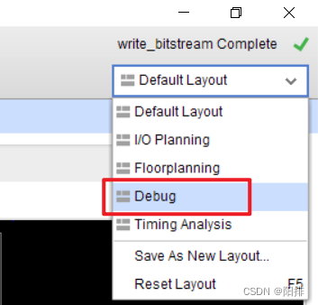
会弹出Schematic原理图和Netlist网表。
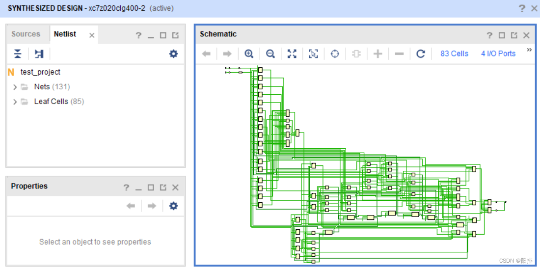
2、打开Netlist网表的Nets列表,选择需要的信号的buffer缓冲器标记为Debug信号。
- 选择复位信号sys_rst_n_IBUF(输入缓冲器),右键点击
Mark Debug。

- 选择LED控制信号led_OBUF(输出缓冲器),右键点击
Mark Debug。

3、修改不完整的变量:
观察网表内cnt计数器的缓冲器不完整,这是由于vivado会对代码进行优化,导致部分缓冲器被取消,如果需要使用debug观察完整的变量,需要在代码内修改语句,添加(*mark_debug = "true"*),一方面是防止对该变量进行优化,另一方面可以将该变量直接添加到debug列表中。
修改后的代码如下:
// 000_test_project2.v
module test_project(
    input sys_clk,
    input sys_rst_n,

    output [1:0] led
);

// reg define
(*mark_debug = "true"*) reg [25:0] cnt;

// 未修改的部分已省略

endmodule
然后重新进行综合。
编译完成后重新打开网表(Reload)。
4、由于刚才的修改,cnt已经被自动加入到debug的列表中,再次添加led_OBUF和sys_rst_n_IBUF两个变量。

5、点击Set Up Debug;弹出的窗口中点击Next;然后可以选择时钟域Clock Domain(此处不进行变更),点击Next;Sample of data depth可以设置采样深度,点击Next;点击Finish。
6、保存设置:Ctrl+S保存,点击OK。关闭Sythesis Design界面。
以上所有对debug的设置都会以命令行的形式保存在.xdc文件内,具体内容如下:
set_property PACKAGE_PIN U18 [get_ports sys_clk]
set_property IOSTANDARD LVCMOS33 [get_ports sys_clk]
set_property IOSTANDARD LVCMOS33 [get_ports sys_rst_n]
set_property PACKAGE_PIN N16 [get_ports sys_rst_n]
set_property IOSTANDARD LVCMOS33 [get_ports {led[1]}]
set_property IOSTANDARD LVCMOS33 [get_ports {led[0]}]
set_property PACKAGE_PIN L15 [get_ports {led[1]}]
set_property PACKAGE_PIN H15 [get_ports {led[0]}]

set_property MARK_DEBUG true [get_nets {led_OBUF[0]}]
set_property MARK_DEBUG true [get_nets {led_OBUF[1]}]
set_property MARK_DEBUG true [get_nets sys_rst_n_IBUF]
create_debug_core u_ila_0 ila
set_property ALL_PROBE_SAME_MU true [get_debug_cores u_ila_0]
set_property ALL_PROBE_SAME_MU_CNT 1 [get_debug_cores u_ila_0]
set_property C_ADV_TRIGGER false [get_debug_cores u_ila_0]
set_property C_DATA_DEPTH 1024 [get_debug_cores u_ila_0]
set_property C_EN_STRG_QUAL false [get_debug_cores u_ila_0]
set_property C_INPUT_PIPE_STAGES 0 [get_debug_cores u_ila_0]
set_property C_TRIGIN_EN false [get_debug_cores u_ila_0]
set_property C_TRIGOUT_EN false [get_debug_cores u_ila_0]
set_property port_width 1 [get_debug_ports u_ila_0/clk]
connect_debug_port u_ila_0/clk [get_nets [list sys_clk_IBUF_BUFG]]
set_property PROBE_TYPE DATA_AND_TRIGGER [get_debug_ports u_ila_0/probe0]
set_property port_width 26 [get_debug_ports u_ila_0/probe0]
connect_debug_port u_ila_0/probe0 [get_nets [list {cnt[0]} {cnt[1]} {cnt[2]} {cnt[3]} {cnt[4]} {cnt[5]} {cnt[6]} {cnt[7]} {cnt[8]} {cnt[9]} {cnt[10]} {cnt[11]} {cnt[12]} {cnt[13]} {cnt[14]} {cnt[15]} {cnt[16]} {cnt[17]} {cnt[18]} {cnt[19]} {cnt[20]} {cnt[21]} {cnt[22]} {cnt[23]} {cnt[24]} {cnt[25]}]]
create_debug_port u_ila_0 probe
set_property PROBE_TYPE DATA_AND_TRIGGER [get_debug_ports u_ila_0/probe1]
set_property port_width 2 [get_debug_ports u_ila_0/probe1]
connect_debug_port u_ila_0/probe1 [get_nets [list {led_OBUF[0]} {led_OBUF[1]}]]
create_debug_port u_ila_0 probe
set_property PROBE_TYPE DATA_AND_TRIGGER [get_debug_ports u_ila_0/probe2]
set_property port_width 1 [get_debug_ports u_ila_0/probe2]
connect_debug_port u_ila_0/probe2 [get_nets [list sys_rst_n_IBUF]]
set_property C_CLK_INPUT_FREQ_HZ 300000000 [get_debug_cores dbg_hub]
set_property C_ENABLE_CLK_DIVIDER false [get_debug_cores dbg_hub]
set_property C_USER_SCAN_CHAIN 1 [get_debug_cores dbg_hub]
connect_debug_port dbg_hub/clk [get_nets sys_clk_IBUF_BUFG]
7、重新生成比特流Generate Bitstream。
此方法相对于ila IP核,也会消耗FPGA的硬件资源。
8、连接开发板进行测试,烧写程序,调试方法与第5节相同。
9、设置对复位按键的下降沿触发,sys_rst_n_IBUF设置为F。然后点击左上角的自动触发(Toggle auto re-trigger mode for this ILA core)。按下开发板上的reset按钮,软件就能捕获到信号变化,并显示在波形图上。

10、调试完成后,可以直接删除.xdc文件内下方的debug_core相关的代码。
set_property MARK_DEBUG true [get_nets {led_OBUF[0]}]
set_property MARK_DEBUG true [get_nets {led_OBUF[1]}]
set_property MARK_DEBUG true [get_nets sys_rst_n_IBUF]
create_debug_core u_ila_0 ila
set_property ALL_PROBE_SAME_MU true [get_debug_cores u_ila_0]
set_property ALL_PROBE_SAME_MU_CNT 1 [get_debug_cores u_ila_0]
set_property C_ADV_TRIGGER false [get_debug_cores u_ila_0]
set_property C_DATA_DEPTH 1024 [get_debug_cores u_ila_0]
set_property C_EN_STRG_QUAL false [get_debug_cores u_ila_0]
set_property C_INPUT_PIPE_STAGES 0 [get_debug_cores u_ila_0]
set_property C_TRIGIN_EN false [get_debug_cores u_ila_0]
set_property C_TRIGOUT_EN false [get_debug_cores u_ila_0]
set_property port_width 1 [get_debug_ports u_ila_0/clk]
connect_debug_port u_ila_0/clk [get_nets [list sys_clk_IBUF_BUFG]]
set_property PROBE_TYPE DATA_AND_TRIGGER [get_debug_ports u_ila_0/probe0]
set_property port_width 26 [get_debug_ports u_ila_0/probe0]
connect_debug_port u_ila_0/probe0 [get_nets [list {cnt[0]} {cnt[1]} {cnt[2]} {cnt[3]} {cnt[4]} {cnt[5]} {cnt[6]} {cnt[7]} {cnt[8]} {cnt[9]} {cnt[10]} {cnt[11]} {cnt[12]} {cnt[13]} {cnt[14]} {cnt[15]} {cnt[16]} {cnt[17]} {cnt[18]} {cnt[19]} {cnt[20]} {cnt[21]} {cnt[22]} {cnt[23]} {cnt[24]} {cnt[25]}]]
create_debug_port u_ila_0 probe
set_property PROBE_TYPE DATA_AND_TRIGGER [get_debug_ports u_ila_0/probe1]
set_property port_width 2 [get_debug_ports u_ila_0/probe1]
connect_debug_port u_ila_0/probe1 [get_nets [list {led_OBUF[0]} {led_OBUF[1]}]]
create_debug_port u_ila_0 probe
set_property PROBE_TYPE DATA_AND_TRIGGER [get_debug_ports u_ila_0/probe2]
set_property port_width 1 [get_debug_ports u_ila_0/probe2]
connect_debug_port u_ila_0/probe2 [get_nets [list sys_rst_n_IBUF]]
set_property C_CLK_INPUT_FREQ_HZ 300000000 [get_debug_cores dbg_hub]
set_property C_ENABLE_CLK_DIVIDER false [get_debug_cores dbg_hub]
set_property C_USER_SCAN_CHAIN 1 [get_debug_cores dbg_hub]
connect_debug_port dbg_hub/clk [get_nets sys_clk_IBUF_BUFG]
然后将.v文件中的(*mark_debug = "true"*)删除。
重新生成比特流就可以了。


![[C#][opencvsharp]C#使用opencvsharp进行年龄和性别预测支持视频图片检测](https://img-blog.csdnimg.cn/direct/ce6fe244d81a49caa29af93f58bb06a8.png)
