描述
定时路径由设计元素之间的连接来定义。在数字中
在设计中,时序路径是由一对受其控制的顺序元件形成的
或者通过两个不同的时钟来启动和捕获信号。
在典型的定时路径中,数据在一个内的两个连续单元之间传输
时钟周期。例如,启动边缘发生在时间0ns;并且出现捕获边缘
一个时钟周期之后。
最常见的定时路径是:
•从输入端口到内部顺序单元的路径
•从一个顺序单元到另一个顺序单元格的内部路径
•从内部顺序单元到输出端口的路径
•从输入端口到输出端口的路径
每个定时路径都由唯一的起点、通过点和终点定义。一条路径
startpoint是顺序单元时钟引脚或数据输入端口;并且路径端点是
顺序单元数据输入引脚或数据输出端口。
TIMING_PATH对象可以通过不同程度的细节进行选择或指定。单个
唯一的定时路径由起点、通过点和终点的组合定义。
可以从一个公共起点或一个公共端点指定多个定时路径。
根据定时的定义,可以将约束应用于定时路径
路径应用于定时路径的约束的优先级,从最高到
最低,如下所示:
1.从-到-到(一个独特的定时路径)
2.-从-到
3.从-到
4.-来自
5.-到
6.-至
7.-通过(通过该点的任何定时路径)
有关定时路径的更多信息,请参阅Vivado Design Suite用户指南:设计
分析和闭合技术(UG906
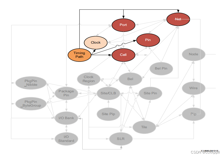
可以使用get_TIMING_PATH命令查询TIMING_PATH对象。这允许
可以使用相关的CLOCK、PIN、PORT或CELL对象来指定定时路径
感兴趣的路径上的起点、通过点或终点。
get_timing_paths-来自fftEngine/control_reg[1]-最大路径10
此外,您还可以查询与指定的相关联的CELL、NET、PIN或PORT对象
定时路径:
get_nets-of_objects[get_timing_paths-max_paths 10]
属性
TIMING_PATH对象上的属性包括以下内容和示例值:
Property Type Read-only Visible Value
CLASS string true true timing_path
CLOCK_PESSIMISM double true true -0.661
CORNER string true true Slow
DATAPATH_DELAY double true true 6.934
DELAY_TYPE string true true max
ENDPOINT_CLOCK clock true true cpuClk_3
ENDPOINT_CLOCK_DELAY double true true -2.149
ENDPOINT_CLOCK_EDGE double true true 20.000
ENDPOINT_PIN pin true true
cpuEngine/or1200_immu_top/qmemimmu_cycstb_o_reg/D
EXCEPTION string true true
GROUP string true true cpuClk_3
INPUT_DELAY double true true
INTER_SLR_COMPENSATION double true true
LOGIC_LEVELS int true true 16
NAME string true true {usbEngine0/u4/inta_reg/C -->
cpuEngine/or1200_immu_top/qmemimmu_cycstb_o_reg/D}
OUTPUT_DELAY double true true
REQUIREMENT double true true 10.000
SKEW double true true -0.057
SLACK double true true 2.865
STARTPOINT_CLOCK clock true true usbClk_2
STARTPOINT_CLOCK_DELAY double true true -2.754
STARTPOINT_CLOCK_EDGE double true true 10.000
STARTPOINT_PIN pin true true usbEngine0/u4/inta_reg/C
UNCERTAINTY double true true 0.202
USER_UNCERTAINTY double true true
The properties of TIMING_PATH objects can be reported with the following command:
report_property -all [lindex [get_timing_paths] 0]


