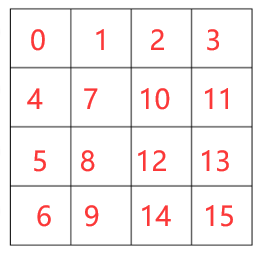
前面的教程中,我们用彩虹的所有颜色画了一个正方形。然而,还有另一种成为纹理映射的技术,将光栅二维图像应用于三维几何。在这种情况下,效果不是针对几何体的顶点,而是通过栅格化场景更改获得的所有像素的数据。这种技术可以显着增加最终图像的真实感和细节。

OSG 支持多种纹理属性和纹理模式。但是,在讨论纹理之前,让我们先谈谈OSG如何在光栅图像上运行。为了处理光栅图像,OSG提供了一个特殊的类osg ::Image ,它在其自身中存储图像数据,最终用于对象的纹理处理。
1、光栅图像数据的表示
从磁盘加载图像的最佳方法是使用 osgDB::readImageFile()调用。它与 osg::readNodeFile() 调用非常相似。如果我们有一个名为 picture.bmp 的位图,那么它的加载将如下所示:
osg::ref_ptr<osg::Image> image = osgDB::readImageFile("picture.bmp");
如果图像加载正确,则指针将有效,否则函数将返回 NULL。加载图像后,我们可以使用以下公共方法获取有关图像的信息。
- t(), s() 和 r() - 返回图像的宽度、高度和深度。
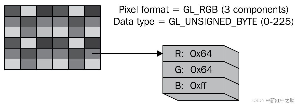
- data() - 返回指向原始图像数据的 unsigned char* 指针。通过此指针,开发人员可以直接影响图像数据。你可以使用 getPixalFormat()和 getDataType()方法了解图像数据的格式。它们返回的值等效于 OpenGL 函数 glTexImage *()的格式和类型的参数。例如,如果图片具有像素格式GL_RGB并且类型为GL_UNSIGNED_BYTE,则使用三个 unsigned char 类型的独立元素来表示 RGB 颜色组件:
你可以创建新的图像对象并为其分配内存。
osg::ref_ptr<osg::Image> image = new osg::Image;
image->allocateImage(s, t, r, GL_RGB, GL_UNSIGNED_BYTE);
unsignedchar *ptr = image->data();
// Далее выполняем с буфером данных изображения любые операции
这里 s、t、r 是图像的尺寸;GL_RGB设置像素格式,GL_UNSIGNED_BYTE设置数据类型以描述单个颜色分量。所需大小的内部数据缓冲区在内存中分配,如果没有对此映像的引用,则会自动销毁。
OSG插件系统支持下载几乎所有流行的图像格式:* .jpg,* .bmp,* .png,* .tif等。通过编写自己的插件,此列表很容易扩展,但这是另一个单独的主题。
2、纹理基础
要将纹理应用于三维模型,必须执行多个步骤:
- 将顶点的纹理坐标分配给几何对象。在三维设计师的环境中,这称为UV扫描。
为 1D、2D、3D 或立方体纹理创建纹理属性对象。 - 为纹理属性设置一个或多个图像。
- 将纹理属性和模式附加到应用于正在绘制的对象的状态集。
OSG 定义了一个 osg::Texture 类来封装各种纹理。子类包括 osg:: Texture1D, osg::Texture2D 、 osg::Texture3D和 osg::TextureCubeMap ,它们代表了OpenGL中采用的各种纹理技术。
osg::Texture 类最常用的方法是 setImage() ,它定义了纹理中使用的图像,例如
osg::ref_ptr<osg::Image> image = osgDB::readImageFile("picture.bmp");
osg::ref_ptr<osg::Texture2D> texture = new osg::Texture2D;
texture->setImage(image.get());
或者,可以将图像对象直接传递给纹理类构造函数。
osg::ref_ptr<osg::Image> image = osgDB::readImageFile("picture.bmp");
osg::ref_ptr<osg::Texture2D> texture = new osg::Texture2D(image.get());
可以通过调用 getImage()方法从纹理对象中检索图像。
另一个要点是设置对象 osg::Geometry中每个顶点的纹理坐标。这些坐标的传输通过 osg::Vec2Array 和 osg::Vec3Array 数组通过调用 setTexCoordArray() 方法进行。
设置纹理坐标后,我们需要设置纹理槽号(unit),因为OSG支持在同一几何体上施加多个纹理。使用一个纹理时,unit的值始终为 0。例如,以下代码演示了单元 0 几何图形的纹理坐标分配
osf::ref_ptr<osg::Vec2Array> texcoord = new osg::Vec2Array;
texcoord->push_back( osg::Vec2(...) );
...
geom->setTexCoordArray(0, texcoord.get());
之后,我们可以向状态集添加一个纹理属性,自动包括相应的纹理模式(在我们的示例中为 GL_TEXTURE_2D),并将该属性应用于包含几何体的几何体或节点
geom->getOrCreateStateSet()->setTextureAttributeAndModes(texture.get());
请注意,OpenGL 管理显卡图形内存中的图像数据,但 osg::Image对象以及相同的数据位于系统内存中。结果,我们将面临这样一个事实,即我们拥有相同数据的两个副本,占用了该过程的内存。如果此图像未由多个纹理属性共享,则可以在 OpenGL 将其传输到视频适配器内存后立即将其从系统内存中删除。若要启用此功能, osg ::Texture类提供了适当的方法。
texture->setUnRefImageDataAfterApply( true );
3、加载并应用 2D 纹理
最常用的 2D 纹理技术是在三维表面的边缘叠加二维图像(或图像)。考虑将单个纹理应用于四边形的最简单示例。
main.h:
#ifndef		MAIN_H
#define		MAIN_H
#include<osg/Texture2D>
#include<osg/Geometry>
#include<osgDB/ReadFile>
#include<osgViewer/Viewer>
#endif
main.cpp
#include"main.h"
intmain(int argc, char *argv[]){
    (void) argc; (void) argv;
    osg::ref_ptr<osg::Vec3Array> vertices = new osg::Vec3Array;
    vertices->push_back( osg::Vec3(-0.5f, 0.0f, -0.5f) );
    vertices->push_back( osg::Vec3( 0.5f, 0.0f, -0.5f) );
    vertices->push_back( osg::Vec3( 0.5f, 0.0f,  0.5f) );
    vertices->push_back( osg::Vec3(-0.5f, 0.0f,  0.5f) );
    osg::ref_ptr<osg::Vec3Array> normals = new osg::Vec3Array;
    normals->push_back( osg::Vec3(0.0f, -1.0f, 0.0f) );
    osg::ref_ptr<osg::Vec2Array> texcoords = new osg::Vec2Array;
    texcoords->push_back( osg::Vec2(0.0f, 0.0f) );
    texcoords->push_back( osg::Vec2(0.0f, 1.0f) );
    texcoords->push_back( osg::Vec2(1.0f, 1.0f) );
    texcoords->push_back( osg::Vec2(1.0f, 0.0f) );
    osg::ref_ptr<osg::Geometry> quad = new osg::Geometry;
    quad->setVertexArray(vertices.get());
    quad->setNormalArray(normals.get());
    quad->setNormalBinding(osg::Geometry::BIND_OVERALL);
    quad->setTexCoordArray(0, texcoords.get());
    quad->addPrimitiveSet( new osg::DrawArrays(GL_QUADS, 0, 4) );
    osg::ref_ptr<osg::Texture2D> texture = new osg::Texture2D;
    osg::ref_ptr<osg::Image> image = osgDB::readImageFile("../data/Images/lz.rgb");
    texture->setImage(image.get());
    osg::ref_ptr<osg::Geode> root = new osg::Geode;
    root->addDrawable(quad.get());
    root->getOrCreateStateSet()->setTextureAttributeAndModes(0, texture.get());
    osgViewer::Viewer viewer;
    viewer.setSceneData(root.get());
    return viewer.run();
}
创建边的顶点和法线数组:
osg::ref_ptr<osg::Vec3Array> vertices = new osg::Vec3Array;
vertices->push_back( osg::Vec3(-0.5f, 0.0f, -0.5f) );
vertices->push_back( osg::Vec3( 0.5f, 0.0f, -0.5f) );
vertices->push_back( osg::Vec3( 0.5f, 0.0f,  0.5f) );
vertices->push_back( osg::Vec3(-0.5f, 0.0f,  0.5f) );
osg::ref_ptr<osg::Vec3Array> normals = new osg::Vec3Array;
normals->push_back( osg::Vec3(0.0f, -1.0f, 0.0f) );
创建纹理坐标数组:
osg::ref_ptr<osg::Vec2Array> texcoords = new osg::Vec2Array;
texcoords->push_back( osg::Vec2(0.0f, 0.0f) );
texcoords->push_back( osg::Vec2(0.0f, 1.0f) );
texcoords->push_back( osg::Vec2(1.0f, 1.0f) );
texcoords->push_back( osg::Vec2(1.0f, 0.0f) );
要点在于三维模型的每个顶点对应于二维纹理上的一个点,并且纹理上点的坐标是相对的 - 它们被归一化为图像的实际宽度和高度。我们要将整个加载的图片分别拉伸到正方形上,正方形的角将对应于纹理点(0,0),(0,1),(1,1)和(1,0)。顶点数组中顶点的顺序必须与纹理顶点的顺序相同。
接下来,创建一个正方形,为几何体分配顶点数组和法线数组:
osg::ref_ptr<osg::Geometry> quad = new osg::Geometry;
quad->setVertexArray(vertices.get());
quad->setNormalArray(normals.get());
quad->setNormalBinding(osg::Geometry::BIND_OVERALL);
quad->setTexCoordArray(0, texcoords.get());
quad->addPrimitiveSet( new osg::DrawArrays(GL_QUADS, 0, 4) );
创建纹理对象并加载用于该对象的图像:
osg::ref_ptr<osg::Texture2D> texture = new osg::Texture2D;
osg::ref_ptr<osg::Image> image = osgDB::readImageFile("../data/Images/lz.rgb");
texture->setImage(image.get());
创建场景的根节点,并将我们创建的几何体加入根节点:
osg::ref_ptr<osg::Geode> root = new osg::Geode;
root->addDrawable(quad.get());
最后将纹理属性应用于放置几何体的节点:
root->getOrCreateStateSet()->setTextureAttributeAndModes(0, texture.get());
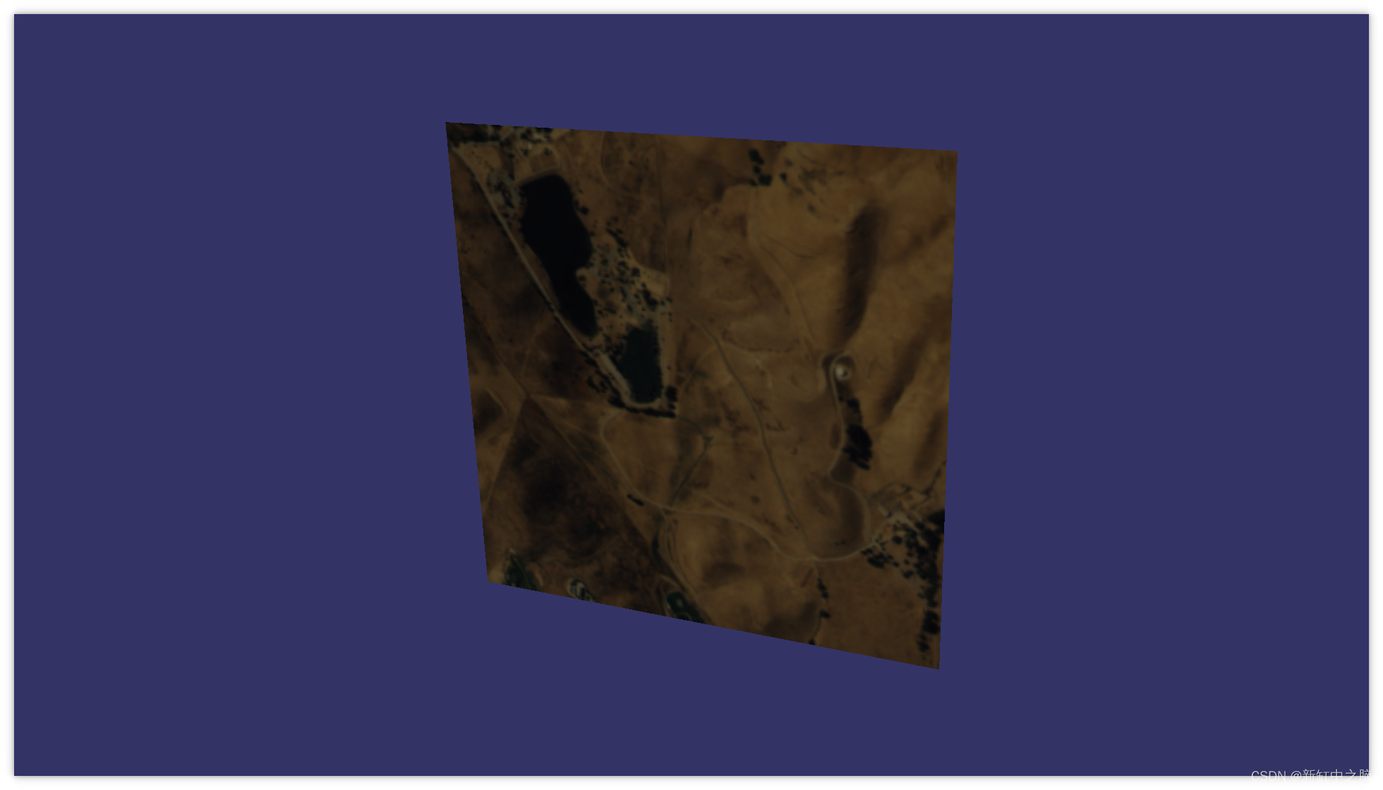
osg:: Texture2D 类确定纹理图像大小是否是 2 的倍数(例如,64x64 或 256x512),实际上使用OpenGL 函数 gluScaleImage ()自动缩放不适合大小的图像。有一个 setResizeNonPowerOfTwoHint()方法可以确定是否调整图像大小。一些视频卡需要图像大小的倍数为2的幂,而类 osg::Texture2D支持使用任意纹理大小。
4、关于纹理映射模式
正如我们已经说过的,纹理坐标从 0 到 1 规范化。点 (0, 0) 对应于图像的左上角,点 (1, 1) 对应于右下角。如果将纹理坐标设置为大于 1,会发生什么情况?
默认情况下,在 OpenGL 中,就像在 OSG 中一样,纹理将在轴的方向上重复,纹理坐标的值将超过单位。例如,这种技术通常用于创建长砖墙的模型,使用小纹理,在宽度和高度上多次重复其施加。
此行为可以通过 osg::Texture 类的 setWrap()方法进行控制。第一个参数表示应用混合模式的轴标识符,第二个参数表示映射模式,例如:
// Повторять текстуру по оси s
texture->setWrap( osg::Texture::WRAP_S, osg::Texture::REPEAT );
// Повторять текстуру по оси r
texture->setWrap( osg::Texture::WRAP_R, osg::Texture::REPEAT );
如果纹理坐标的值超过 1,此代码会清楚地指示引擎沿 s 轴和 r 轴重复纹理。按纹理映射模式的完整列表:
- REPEAT - 重复纹理。
- MIRROR - 镜像重复纹理。
- CLAMP_TO_EDGE — 超出 0 到 1 限制的坐标将附加到相应的纹理边缘。
- CLAMP_TO_BORDER - 超出 0 到 1 限制的坐标将提供用户定义的边框颜色。
5、渲染到纹理
纹理渲染技术允许开发人员基于一些三维子舞台或模型创建纹理,并将其应用于主场景的表面。这项技术通常被称为纹理烘焙(texture baking)。
对于动态烘焙纹理,必须执行三个步骤:
- 创建一个纹理对象以渲染到其中。
- 将场景渲染为纹理。
- 按预期使用生成的纹理。
我们需要创建一个空的纹理对象。OSG允许你创建给定大小的空纹理。 setTextureSize() 方法允许你设置纹理的宽度和高度,以及深度作为附加参数(对于 3D 纹理)。
若要将纹理渲染为纹理,可以通过调用 attach() 方法将其附加到相机对象,该方法将纹理对象作为参数。此外,此方法采用一个参数,指示帧缓冲区的哪个部分应呈现为此纹理。例如,若要将颜色缓冲区传输到纹理,可以运行以下代码:
camera->attach( osg::Camera::COLOR_BUFFER, texture.get() );
可用于呈现的帧缓冲区的其他部分包括深度缓冲区DEPTH_BUFFER、模具缓冲区STENCIL_BUFFER以及从COLOR_BUFFER0到COLOR_BUFFER15的其他颜色缓冲区。是否存在其他颜色缓冲区及其数量由视频卡型号决定。
此外,对于渲染纹理的相机,设置投影和视口矩阵的参数,其大小对应于纹理的大小。纹理将在绘制每个帧的过程中更新。请注意,主摄像头不应用于渲染纹理,因为它提供了主场景的渲染,而你只会得到一个黑屏。仅当你执行屏幕外渲染时,可能无法满足此要求。
6、渲染到纹理的实现示例
为了演示渲染到纹理,我们将实现这样一个任务:创建一个正方形,将一个正方形纹理拉伸到上面,当然,我们将用我们最喜欢的纹理渲染一个动画场景。实现该示例的程序非常庞大。但是,我仍然给出完整的源代码。
main.h:
#ifndef		MAIN_H
#define		MAIN_H
#include<osg/Camera>
#include<osg/Texture2D>
#include<osg/MatrixTransform>
#include<osgDB/ReadFile>
#include<osgGA/TrackballManipulator>
#include<osgViewer/Viewer>
#endif
main.cpp:
#include"main.h"
//------------------------------------------------------------------------------
//
//------------------------------------------------------------------------------
osg::Geometry *createQuad(const osg::Vec3 &pos, float w, float h){
    osg::ref_ptr<osg::Vec3Array> vertices = new osg::Vec3Array;
    vertices->push_back( pos + osg::Vec3( w / 2, 0.0f, -h / 2) );
    vertices->push_back( pos + osg::Vec3( w / 2, 0.0f,  h / 2) );
    vertices->push_back( pos + osg::Vec3(-w / 2, 0.0f,  h / 2) );
    vertices->push_back( pos + osg::Vec3(-w / 2, 0.0f, -h / 2) );
    osg::ref_ptr<osg::Vec3Array> normals = new osg::Vec3Array;
    normals->push_back(osg::Vec3(0.0f, -1.0f, 0.0f));
    osg::ref_ptr<osg::Vec2Array> texcoords = new osg::Vec2Array;
    texcoords->push_back( osg::Vec2(1.0f, 1.0f) );
    texcoords->push_back( osg::Vec2(1.0f, 0.0f) );
    texcoords->push_back( osg::Vec2(0.0f, 0.0f) );
    texcoords->push_back( osg::Vec2(0.0f, 1.0f) );
    osg::ref_ptr<osg::Geometry> quad = new osg::Geometry;
    quad->setVertexArray(vertices.get());
    quad->setNormalArray(normals.get());
    quad->setNormalBinding(osg::Geometry::BIND_OVERALL);
    quad->setTexCoordArray(0, texcoords.get());
    quad->addPrimitiveSet(new osg::DrawArrays(GL_QUADS, 0, 4));
    return quad.release();
}
//------------------------------------------------------------------------------
//
//------------------------------------------------------------------------------
int main(int argc, char *argv[]){
    (void) argc; (void) argv;
    osg::ref_ptr<osg::Node> sub_model = osgDB::readNodeFile("../data/cessna.osg");
    osg::ref_ptr<osg::MatrixTransform> transform1 = new osg::MatrixTransform;
    transform1->setMatrix(osg::Matrix::rotate(0.0, osg::Vec3(0.0f, 0.0f, 1.0f)));
    transform1->addChild(sub_model.get());
    osg::ref_ptr<osg::Geode> model = new osg::Geode;
    model->addChild(createQuad(osg::Vec3(0.0f, 0.0f, 0.0f), 2.0f, 2.0f));
    int tex_widht = 1024;
    int tex_height = 1024;
    osg::ref_ptr<osg::Texture2D> texture = new osg::Texture2D;
    texture->setTextureSize(tex_widht, tex_height);
    texture->setInternalFormat(GL_RGBA);
    texture->setFilter(osg::Texture2D::MIN_FILTER, osg::Texture2D::LINEAR);
    texture->setFilter(osg::Texture2D::MAG_FILTER, osg::Texture2D::LINEAR);
    model->getOrCreateStateSet()->setTextureAttributeAndModes(0, texture.get());
    osg::ref_ptr<osg::Camera> camera = new osg::Camera;
    camera->setViewport(0, 0, tex_widht, tex_height);
    camera->setClearColor(osg::Vec4(1.0f, 1.0f, 1.0f, 1.0f));
    camera->setClearMask(GL_COLOR_BUFFER_BIT | GL_DEPTH_BUFFER_BIT);
    camera->setRenderOrder(osg::Camera::PRE_RENDER);
    camera->setRenderTargetImplementation(osg::Camera::FRAME_BUFFER_OBJECT);
    camera->attach(osg::Camera::COLOR_BUFFER, texture.get());
    camera->setReferenceFrame(osg::Camera::ABSOLUTE_RF);
    camera->addChild(transform1.get());
    osg::ref_ptr<osg::Group> root = new osg::Group;
    root->addChild(model.get());
    root->addChild(camera.get());
    osgViewer::Viewer viewer;
    viewer.setSceneData(root.get());
    viewer.setCameraManipulator(new osgGA::TrackballManipulator);
    viewer.setUpViewOnSingleScreen(0);
    camera->setProjectionMatrixAsPerspective(30.0, static_cast<double>(tex_widht) / static_cast<double>(tex_height), 0.1, 1000.0);
    float dist = 100.0f;
    float alpha = 10.0f * 3.14f / 180.0f;
    osg::Vec3 eye(0.0f, -dist * cosf(alpha), dist * sinf(alpha));
    osg::Vec3 center(0.0f, 0.0f, 0.0f);
    osg::Vec3 up(0.0f, 0.0f, -1.0f);
    camera->setViewMatrixAsLookAt(eye, center, up);
    float phi = 0.0f;
    float delta = -0.01f;
    while (!viewer.done())
    {
        transform1->setMatrix(osg::Matrix::rotate(static_cast<double>(phi), osg::Vec3(0.0f, 0.0f, 1.0f)));
        viewer.frame();
        phi += delta;
    }
    return0;
}
为了创建一个正方形,我们编写了一个单独的自由函数。
osg::Geometry *createQuad(const osg::Vec3 &pos, float w, float h){
    osg::ref_ptr<osg::Vec3Array> vertices = new osg::Vec3Array;
    vertices->push_back( pos + osg::Vec3( w / 2, 0.0f, -h / 2) );
    vertices->push_back( pos + osg::Vec3( w / 2, 0.0f,  h / 2) );
    vertices->push_back( pos + osg::Vec3(-w / 2, 0.0f,  h / 2) );
    vertices->push_back( pos + osg::Vec3(-w / 2, 0.0f, -h / 2) );
    osg::ref_ptr<osg::Vec3Array> normals = new osg::Vec3Array;
    normals->push_back(osg::Vec3(0.0f, -1.0f, 0.0f));
    osg::ref_ptr<osg::Vec2Array> texcoords = new osg::Vec2Array;
    texcoords->push_back( osg::Vec2(1.0f, 1.0f) );
    texcoords->push_back( osg::Vec2(1.0f, 0.0f) );
    texcoords->push_back( osg::Vec2(0.0f, 0.0f) );
    texcoords->push_back( osg::Vec2(0.0f, 1.0f) );
    osg::ref_ptr<osg::Geometry> quad = new osg::Geometry;
    quad->setVertexArray(vertices.get());
    quad->setNormalArray(normals.get());
    quad->setNormalBinding(osg::Geometry::BIND_OVERALL);
    quad->setTexCoordArray(0, texcoords.get());
    quad->addPrimitiveSet(new osg::DrawArrays(GL_QUADS, 0, 4));
    return quad.release();
}
该函数将正方形中心的位置及其几何尺寸作为输入。接下来,创建一个顶点数组、一个法线数组和纹理坐标,然后从函数返回创建的几何体。
在主程序的正文中,我们将加载Cessna模型:
osg::ref_ptr<osg::Node> sub_model = osgDB::readNodeFile("../data/cessna.osg");
osg::ref_ptr<osg::MatrixTransform> transform1 = new osg::MatrixTransform;
transform1->setMatrix(osg::Matrix::rotate(0.0, osg::Vec3(0.0f, 0.0f, 1.0f)));
transform1->addChild(sub_model.get());
现在我们将为主场景创建一个模型 - 一个我们将在其上渲染的正方形:
osg::ref_ptr<osg::Geode> model = new osg::Geode;
model->addChild(createQuad(osg::Vec3(0.0f, 0.0f, 0.0f), 2.0f, 2.0f));
使用 RGBA 像素格式为 1024x1024 像素的正方形创建空纹理(带 Alpha 通道的 32 位三分量颜色):
int tex_widht = 1024;
int tex_height = 1024;
osg::ref_ptr<osg::Texture2D> texture = new osg::Texture2D;
texture->setTextureSize(tex_widht, tex_height);
texture->setInternalFormat(GL_RGBA);
texture->setFilter(osg::Texture2D::MIN_FILTER, osg::Texture2D::LINEAR);
texture->setFilter(osg::Texture2D::MAG_FILTER, osg::Texture2D::LINEAR);
将此纹理应用于正方形模型。
model->getOrCreateStateSet()->setTextureAttributeAndModes(0, texture.get());
然后创建一个将烘焙纹理的相机。
osg::ref_ptr<osg::Camera> camera = new osg::Camera;
camera->setViewport(0, 0, tex_widht, tex_height);
camera->setClearColor(osg::Vec4(1.0f, 1.0f, 1.0f, 1.0f));
camera->setClearMask(GL_COLOR_BUFFER_BIT | GL_DEPTH_BUFFER_BIT);
视口相机的大小与纹理的大小一致。此外,清洁屏幕和清洁蒙版时不要忘记设置背景颜色,指示清除颜色缓冲区和深度缓冲区。接下来,设置相机以渲染为纹理:
camera->setRenderOrder(osg::Camera::PRE_RENDER);
camera->setRenderTargetImplementation(osg::Camera::FRAME_BUFFER_OBJECT);
camera->attach(osg::Camera::COLOR_BUFFER, texture.get());
渲染顺序PRE_RENDER指示此摄像机在渲染到主场景之前进行渲染。我们将FBO指定为渲染的目标,并将纹理附加到摄像机。现在我们将摄像机设置为在绝对坐标系中工作,作为场景,我们设置了要渲染为纹理的子树:使用附加的Cessna模型进行旋转转换:
camera->setReferenceFrame(osg::Camera::ABSOLUTE_RF);
camera->addChild(transform1.get());
创建根组节点,向其添加主模型(正方形)和相机处理纹理:
osg::ref_ptr<osg::Group> root = new osg::Group;
root->addChild(model.get());
root->addChild(camera.get());
创建场景查看器:
osgViewer::Viewer viewer;
viewer.setSceneData(root.get());
viewer.setCameraManipulator(new osgGA::TrackballManipulator);
viewer.setUpViewOnSingleScreen(0);
配置相机的投影矩阵 - 通过裁剪金字塔参数的透视投影:
camera->setProjectionMatrixAsPerspective(30.0, static_cast<double>(tex_widht) / static_cast<double>(tex_height), 0.1, 1000.0);
调整视图矩阵,该矩阵设置相机在空间中的位置:
float dist = 100.0f;
float alpha = 10.0f * 3.14f / 180.0f;
osg::Vec3 eye(0.0f, -dist * cosf(alpha), dist * sinf(alpha));
osg::Vec3 center(0.0f, 0.0f, 0.0f);
osg::Vec3 up(0.0f, 0.0f, -1.0f);
camera->setViewMatrixAsLookAt(eye, center, up);
最后,我们对场景进行动画处理和显示,在每一帧上改变平面绕 Z 轴旋转的角度。
float phi = 0.0f;
float delta = -0.01f;
while (!viewer.done())
{
    transform1->setMatrix(osg::Matrix::rotate(static_cast<double>(phi), osg::Vec3(0.0f, 0.0f, 1.0f)));
    viewer.frame();
    phi += delta;
}
最终我们得到一个有趣的结果:
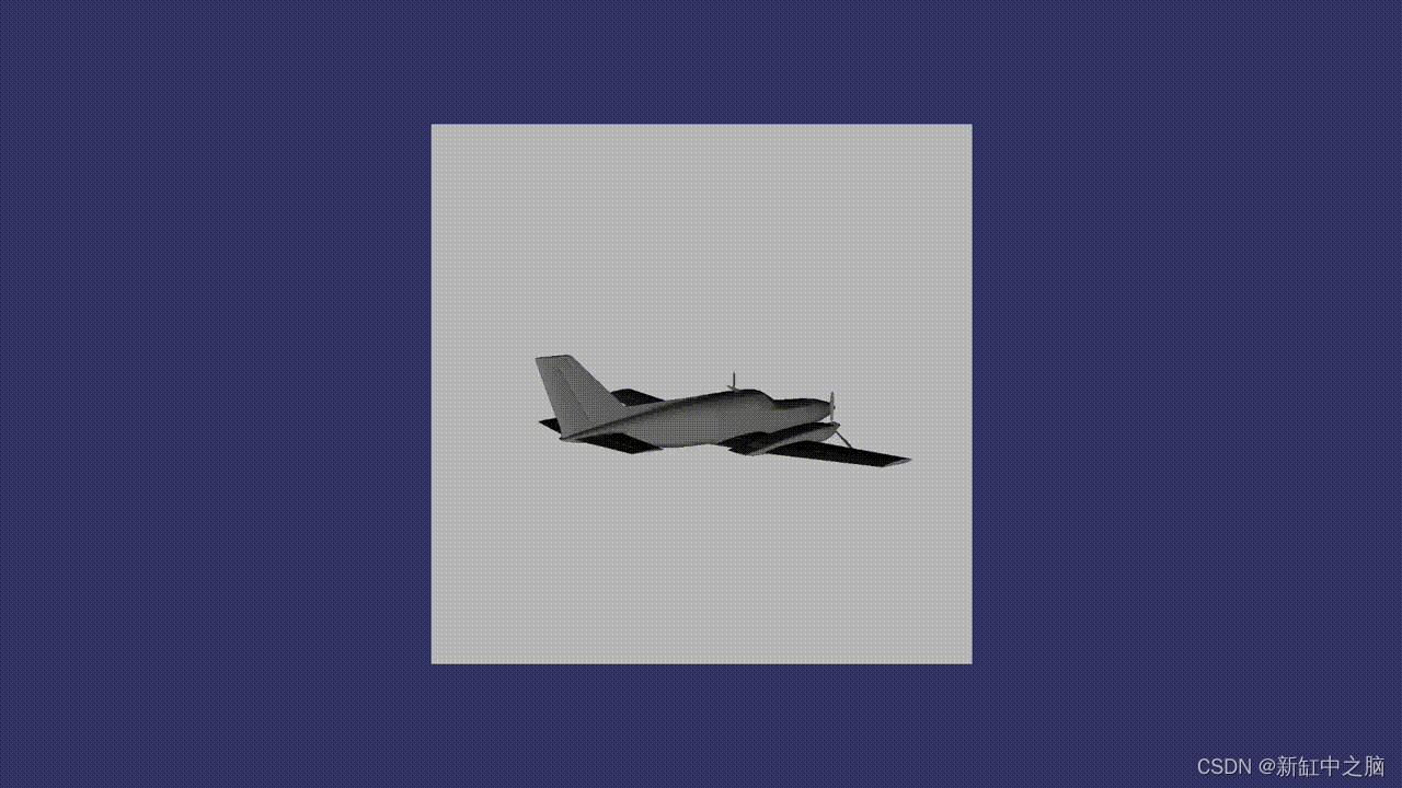
在此示例中,我们实现了一些场景动画,但请记住,从组织对不同流的数据访问的角度来看,在渲染帧之前或之后扩展 run()循环并更改渲染参数并不是一项安全的工作。由于 OSG 使用多线程渲染,因此有一些常规机制可以在渲染过程中嵌入自己的操作,从而提供对数据的线程安全访问。
7、将渲染结果保存到文件
OSG 支持将 osg::Image对象附加到相机并将帧缓冲区的内容保存到图像数据缓冲区的功能。之后,可以使用 osg::writeImageFile()函数将此数据保存到磁盘:
osg::ref_ptr<osg::Image> image = new osg::Image;
image->allocateImage( width, height, 1, GL_RGBA, GL_UNSIGNED_BYTE );
camera->attach( osg::Camera::COLOR_BUFFER, image.get() );
...
osgDB::writeImageFile( *image, "saved_image.bmp" );
8、结束语
也许文章中描述的材料看起来微不足道。但是,它概述了在OpenSceneGraph中使用纹理的基础知识,这些基础知识基于使用此引擎的更复杂的技术,我们将来肯定会讨论。
原文链接:OSG纹理快速入门 — BimAnt


