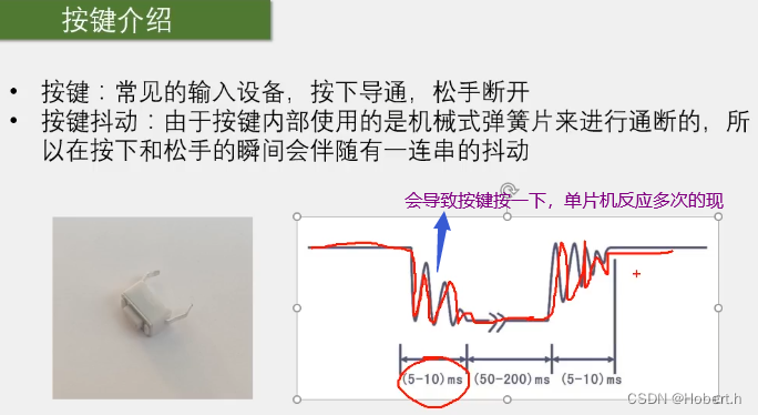
一.硬件
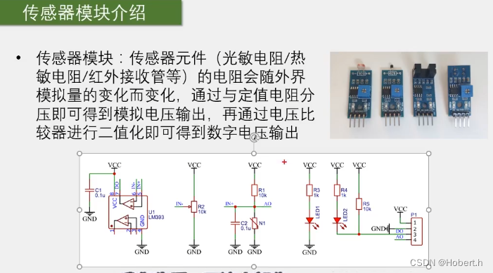
光线越强,光敏电阻的阻值越小
温度越高,热敏电阻的阻值就越小
红外光线越强,红外接收管的阻值就越小
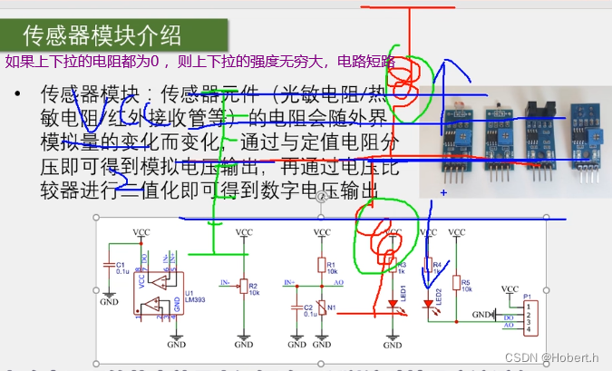
类比:电阻阻值越小,上拉或下拉就越强 (弹簧的拉力就越强)
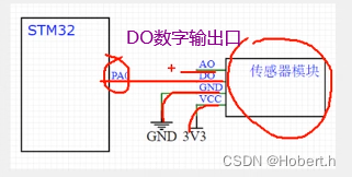
在上下的电阻分压下,AO口输出的就是模拟电压
对模拟电压进行二值化
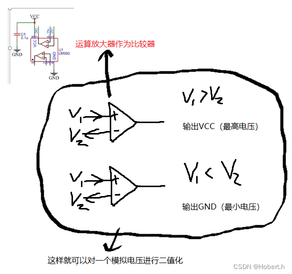
 N1就是传感器模块
二.硬件电路
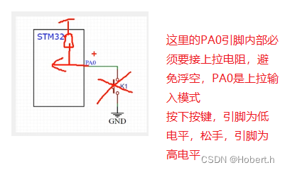
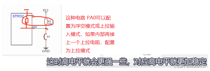
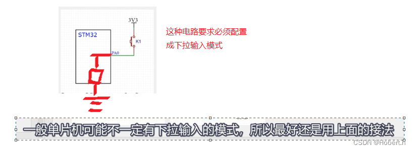
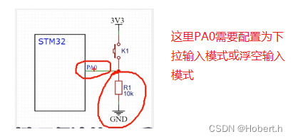
上面这一个电路,当引脚被强行拉到低时,损耗也会大一些
三.C语言基础
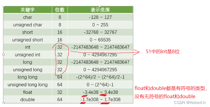
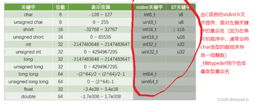 stdint定义的是新版本的,ST是老版本的


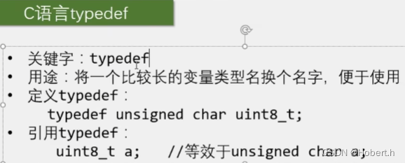
typedef后面必须加“;”,只能给变量类型换名,但对于变量类型重命名而言,typedef更加安全
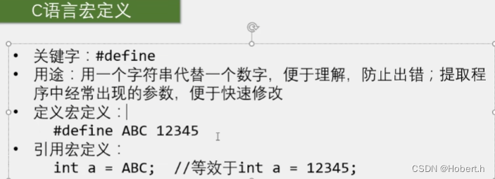
define后面不需要加分号,如何名字都可以换


四.代码实现
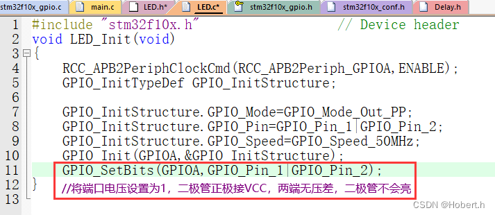
GPIO配置好之后默认就是低电平,所以要在LED_Init最后加上GPIO_SetBits(...);
ctrl+Alt+空格:弹出代码提示框
---------------------------------------------------------------------------------------------------------------------------------
注:
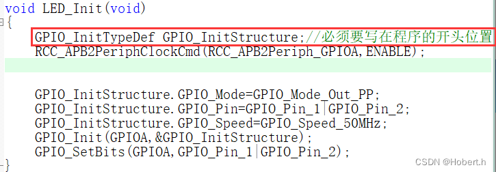
局部变量的定义
---------------------------------------------------------------------------------------------------------------------------------

--------------------------------------------------------------------------------------------------------------------------------
1.按键控制LED
(1)自己的代码逻辑
LED.c
#include "stm32f10x.h"                  // Device header
void LED_Init(void)
{
	GPIO_InitTypeDef GPIO_InitStructure;//必须要写在程序的开头位置
	RCC_APB2PeriphClockCmd(RCC_APB2Periph_GPIOA,ENABLE);


	GPIO_InitStructure.GPIO_Mode=GPIO_Mode_Out_PP;
	GPIO_InitStructure.GPIO_Pin=GPIO_Pin_1|GPIO_Pin_2;
	GPIO_InitStructure.GPIO_Speed=GPIO_Speed_50MHz;
	GPIO_Init(GPIOA,&GPIO_InitStructure);
	GPIO_SetBits(GPIOA,GPIO_Pin_1|GPIO_Pin_2);
}
void LED1_ON(void)
{
	GPIO_ResetBits(GPIOA,GPIO_Pin_1);
}
void LED1_OFF(void)
{
	GPIO_SetBits(GPIOA,GPIO_Pin_1);
}
void LED2_ON(void)
{
	GPIO_ResetBits(GPIOA,GPIO_Pin_2);
}
void LED2_OFF(void)
{
	GPIO_SetBits(GPIOA,GPIO_Pin_2);
}
main.c
#include "stm32f10x.h"                  // Device header
#include "Delay.h"
#include "LED.h"
#include "Key.h"
uint8_t KeyNum,count1,count2;
int main()
{
	LED_Init();
	Key_Init();
	while(1)
	{
		KeyNum=Keynum();
		if(KeyNum==1)
		{
			count1++;
			if(count1%2==0)
			{
				if(KeyNum==1)
				{
					LED1_OFF();
				}
			}
			else
			{
				if(KeyNum==1)
				{
					LED1_ON();
				}
			}
		}
		if(KeyNum==2)
		{
			count2++;
			if(count2%2==0)
			{

				if(KeyNum==2)
				{
					LED2_OFF();
				}

			}
			else
			{
				if(KeyNum==2)
				{
					LED2_ON();
				}
			}
		}
	}
}
(2)视频的代码逻辑
LED.c
#include "stm32f10x.h"                  // Device header
void LED_Init(void)
{
	GPIO_InitTypeDef GPIO_InitStructure;//必须要写在程序的开头位置
	RCC_APB2PeriphClockCmd(RCC_APB2Periph_GPIOA,ENABLE);


	GPIO_InitStructure.GPIO_Mode=GPIO_Mode_Out_PP;
	GPIO_InitStructure.GPIO_Pin=GPIO_Pin_1|GPIO_Pin_2;
	GPIO_InitStructure.GPIO_Speed=GPIO_Speed_50MHz;
	GPIO_Init(GPIOA,&GPIO_InitStructure);
	GPIO_SetBits(GPIOA,GPIO_Pin_1|GPIO_Pin_2);
}
void LED1_ON(void)
{
	GPIO_ResetBits(GPIOA,GPIO_Pin_1);
}
void LED1_OFF(void)
{
	GPIO_SetBits(GPIOA,GPIO_Pin_1);
}
void LED1_Turn(void)//实现IO口翻转
{
	if(GPIO_ReadOutputDataBit(GPIOA,GPIO_Pin_1)==0)
	{
		GPIO_SetBits(GPIOA,GPIO_Pin_1);

	}
	else
	{

		GPIO_ResetBits(GPIOA,GPIO_Pin_1);
	}
}
void LED2_ON(void)
{
	GPIO_ResetBits(GPIOA,GPIO_Pin_2);
}
void LED2_OFF(void)
{
	GPIO_SetBits(GPIOA,GPIO_Pin_2);
}
void LED2_Turn(void)
{
	if(GPIO_ReadOutputDataBit(GPIOA,GPIO_Pin_2)==0)
	{
		GPIO_SetBits(GPIOA,GPIO_Pin_2);

	}
	else
	{

		GPIO_ResetBits(GPIOA,GPIO_Pin_2);
	}
}
main.c
#include "stm32f10x.h"                  // Device header
#include "Delay.h"
#include "LED.h"
#include "Key.h"
uint8_t KeyNum,count1,count2;
int main()
{
	LED_Init();
	Key_Init();
	while(1)
	{
		KeyNum=Keynum();
		if(KeyNum==1)
		{
			LED1_Turn();
		}
		if(KeyNum==2)
		{
			LED2_Turn();
		}

	}
}
2.光敏控制蜂鸣器
Buzzer.c
#include "stm32f10x.h"                  // Device header
void Buzzer_Init(void)
{
	GPIO_InitTypeDef GPIO_InitStructure;//必须要写在程序的开头位置
	RCC_APB2PeriphClockCmd(RCC_APB2Periph_GPIOB,ENABLE);
	GPIO_InitStructure.GPIO_Mode=GPIO_Mode_Out_PP;
	GPIO_InitStructure.GPIO_Pin=GPIO_Pin_12;
	GPIO_InitStructure.GPIO_Speed=GPIO_Speed_50MHz;
	GPIO_Init(GPIOB,&GPIO_InitStructure);
	GPIO_SetBits(GPIOB,GPIO_Pin_12);
}
void Buzzer_ON(void)
{
	GPIO_ResetBits(GPIOB,GPIO_Pin_12);
}
void Buzzer_OFF(void)
{
	GPIO_SetBits(GPIOB,GPIO_Pin_12);
}
void Buzzer_Turn(void)
{
	if(GPIO_ReadOutputDataBit(GPIOB,GPIO_Pin_12)==0)
	{
		GPIO_SetBits(GPIOB,GPIO_Pin_12);

	}
	else
	{

		GPIO_ResetBits(GPIOB,GPIO_Pin_12);
	}
}
main.c
#include "stm32f10x.h"                  // Device header
#include "Delay.h"
#include "LED.h"
#include "Key.h"
#include "Buzzer.h"
#include "LightSensor.h"
uint8_t KeyNum,count1,count2;
int main()
{
	Buzzer_Init();
	LightSensor_Init();
//	Buzzer_OFF();
	while(1)
	{
		if(LightSensor_get()==0)
		{
			Buzzer_OFF();
		}
		else
		{
			Buzzer_ON();
		}
	}
}
