STM32实现USB转TTL串口工具
具有USB接口和UART接口的STM32芯片,如STM32F1, STM32F4等等,都可以实现USB转TTL串口工具的制作。目前具有USB接口的最小资源的芯片是STM32F103C6T6。这里介绍USB转UART的代码设计。
STM32例化的USB VCOM,数据通讯到STM32内部设定的缓存空间,如果不向外部进行UART转发,则VCOM的波特率为名义上的波特率,实际上是按照USB接口自动协商的差分速率在进行数据传输。在向外部进行UART转发时,UART的波特率可以单独配置,并不需要和VCOM端配置的名义上的波特率相同。而在向外部进行UART转发,且UART的波特率与VCOM的波特率一致时,也就实现了USB转TTL串口工具,设计的要点一是将USB传递的VCOM波特率信息,用于配置转发的UART的波特率;二是通过终端,DMA和缓存方式的配合,实现有效的时序转发。
如下介绍基本的USB转TTL串口转发逻辑设计,一些高级串口控制功能可以根据需要增加调整。
STM32工程配置
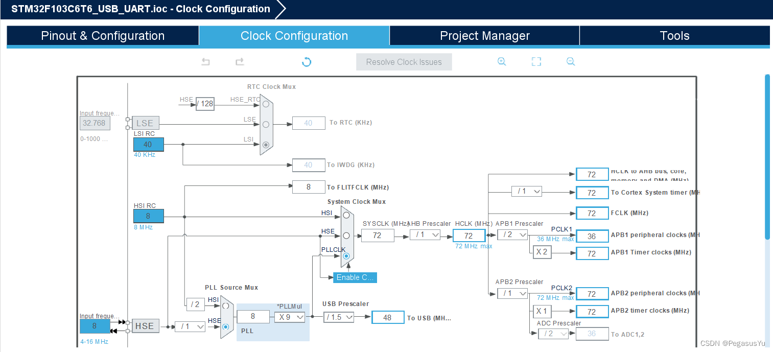
首先建立基本工程并配置时钟:
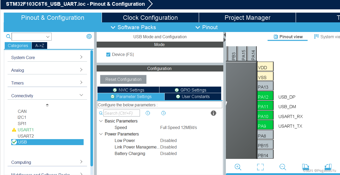
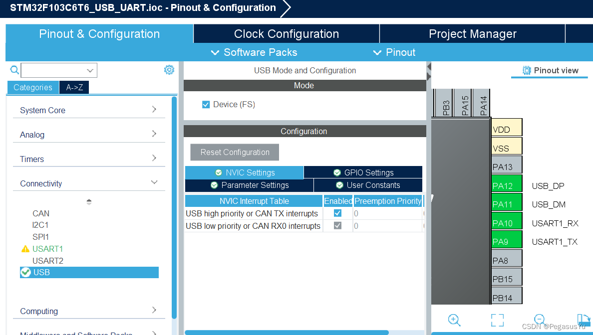
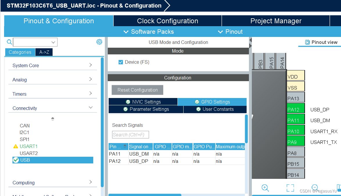
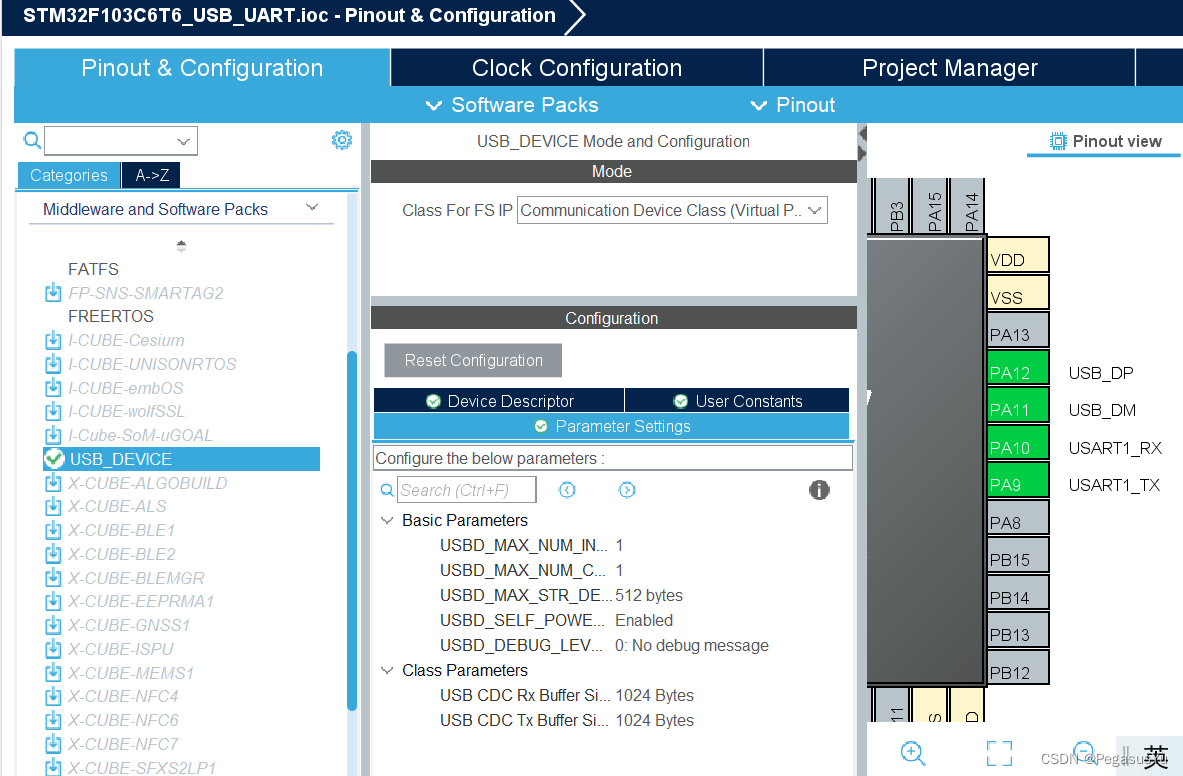
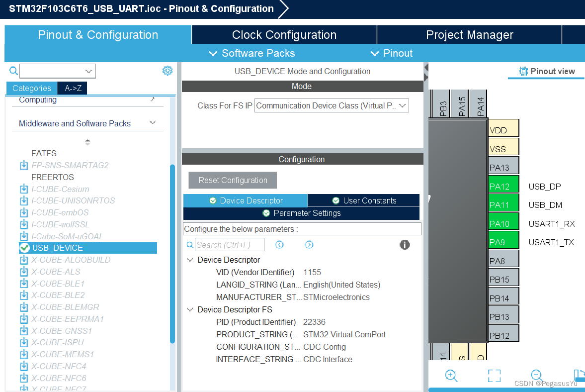
配置USB VCOM:
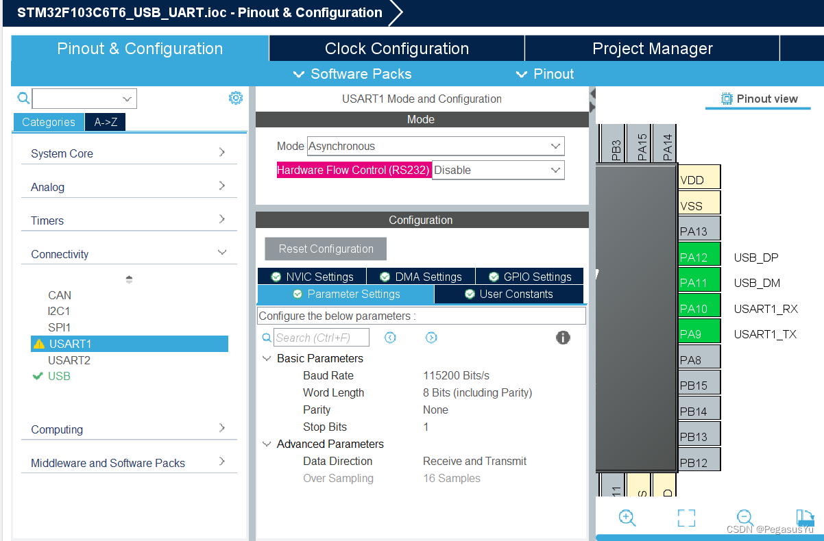
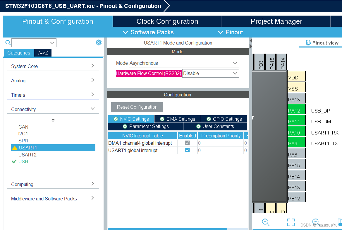
配置UART1作为转发串口:
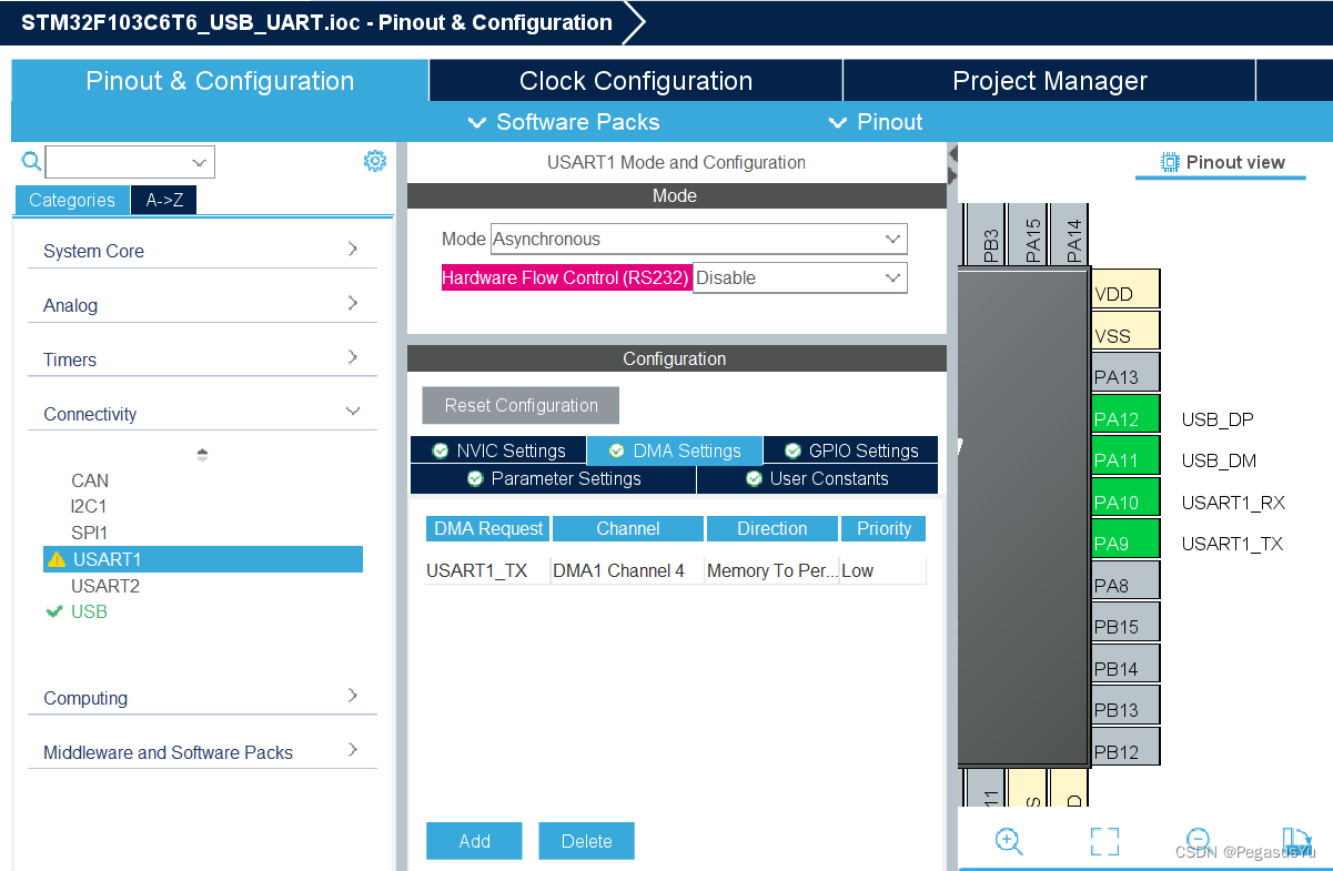
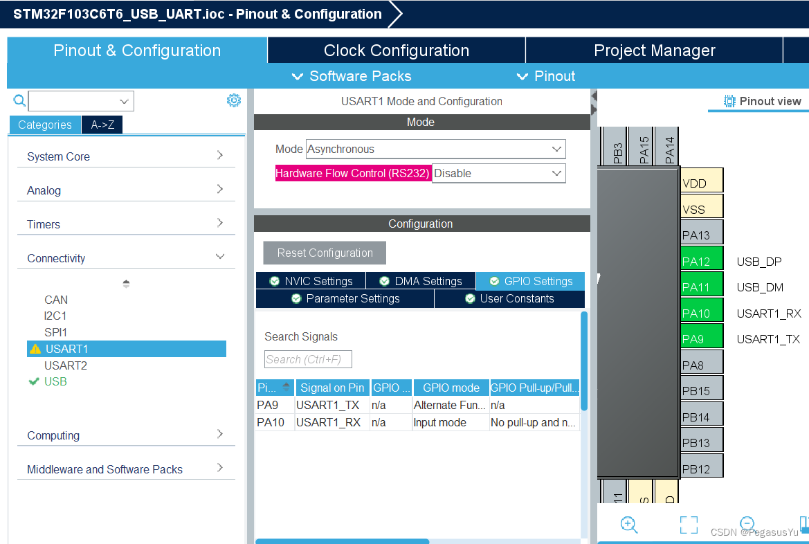
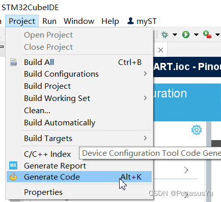
保存并生成初始工程代码:
STM32工程代码
首先在usbd_cdc_if.c修改代码获取VCOM配置信息(事件自动触发)并重新配置转发串口UART1的波特率:
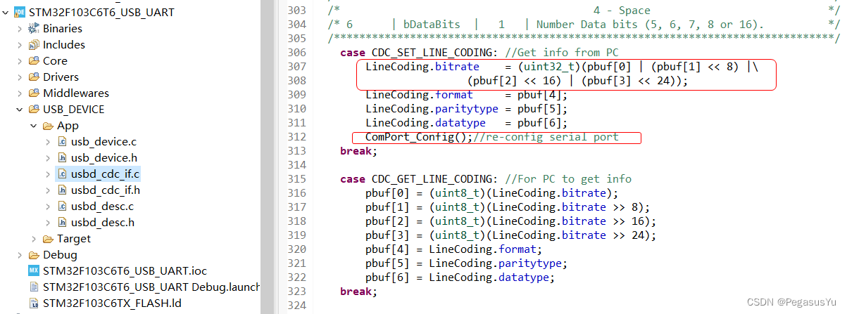
在重新配置转发串口UART1的波特率后,修改识别标识,main.c主程序里识别后开启UART1的单字节中断接收,并采用缓存方式解决通过USB VCOM转发未完成而UART1继续接收到数据的情况。当主程序里识别到UART1缓存区域有数据,则转存后通过USB VCOM发送出去,并修改UART1接收缓存区接收索引位置。
USB VCOM收到的数据,通过UART1的发送DMA方式发送出去。并且通过UART1的发送完成中断进行标识设置,代码通过缓存方式解决USB VCOM收到新的数据而UART1的数据发送未完成的情况。
usbd_cdc_if.c修改后的完整实现代码:
/* USER CODE BEGIN Header */
/**
  ******************************************************************************
  * @file           : usbd_cdc_if.c
  * @version        : v2.0_Cube
  * @brief          : Usb device for Virtual Com Port.
  ******************************************************************************
  * @attention
  *
  * Copyright (c) 2023 STMicroelectronics.
  * All rights reserved.
  *
  * This software is licensed under terms that can be found in the LICENSE file
  * in the root directory of this software component.
  * If no LICENSE file comes with this software, it is provided AS-IS.
  *
  ******************************************************************************
  */
/* USER CODE END Header */

/* Includes ------------------------------------------------------------------*/
#include "usbd_cdc_if.h"

/* USER CODE BEGIN INCLUDE */
#include "main.h"
/* USER CODE END INCLUDE */

/* Private typedef -----------------------------------------------------------*/
/* Private define ------------------------------------------------------------*/
/* Private macro -------------------------------------------------------------*/

/* USER CODE BEGIN PV */
/* Private variables ---------------------------------------------------------*/
USBD_CDC_LineCodingTypeDef LineCoding =
{
    115200, /* Baud-rate:115200*/
    0x00,   /* Stop Bit:1*/
    0x00,   /* Verification: none*/
    0x08    /* Data bits: 8*/
};


void ComPort_Config(void)
{
  extern UART_HandleTypeDef huart1;
  extern uint8_t uart1_reconfig_flag;
  if(HAL_UART_DeInit(&huart1) != HAL_OK)
  {
    /* Initialization Error */
    Error_Handler();
  }

  /* set the Stop bit */
  switch (LineCoding.format)
  {
  case 0:
    huart1.Init.StopBits = UART_STOPBITS_1;
    break;
  case 2:
    huart1.Init.StopBits = UART_STOPBITS_2;
    break;
  default :
    huart1.Init.StopBits = UART_STOPBITS_1;
    break;
  }

  /* set the parity bit*/
  switch (LineCoding.paritytype)
  {
  case 0:
    huart1.Init.Parity = UART_PARITY_NONE;
    break;
  case 1:
    huart1.Init.Parity = UART_PARITY_ODD;
    break;
  case 2:
    huart1.Init.Parity = UART_PARITY_EVEN;
    break;
  default :
    huart1.Init.Parity = UART_PARITY_NONE;
    break;
  }

  /*set the data type : only 8bits and 9bits is supported */
  switch (LineCoding.datatype)
  {
  case 0x07:
    /* With this configuration a parity (Even or Odd) must be set */
    huart1.Init.WordLength = UART_WORDLENGTH_8B;
    break;
  case 0x08:
    if(huart1.Init.Parity == UART_PARITY_NONE)
    {
      huart1.Init.WordLength = UART_WORDLENGTH_8B;
    }
    else
    {
      huart1.Init.WordLength = UART_WORDLENGTH_9B;
    }

    break;
  default :
    huart1.Init.WordLength = UART_WORDLENGTH_8B;
    break;
  }

  huart1.Init.BaudRate     = LineCoding.bitrate;
  huart1.Init.HwFlowCtl    = UART_HWCONTROL_NONE;
  huart1.Init.Mode         = UART_MODE_TX_RX;
  huart1.Init.OverSampling = UART_OVERSAMPLING_16;

  if(HAL_UART_Init(&huart1) != HAL_OK)
  {
    /* Initialization Error */
    Error_Handler();
  }

  uart1_reconfig_flag = 1;
}

/* USER CODE END PV */

/** @addtogroup STM32_USB_OTG_DEVICE_LIBRARY
  * @brief Usb device library.
  * @{
  */

/** @addtogroup USBD_CDC_IF
  * @{
  */

/** @defgroup USBD_CDC_IF_Private_TypesDefinitions USBD_CDC_IF_Private_TypesDefinitions
  * @brief Private types.
  * @{
  */

/* USER CODE BEGIN PRIVATE_TYPES */

/* USER CODE END PRIVATE_TYPES */

/**
  * @}
  */

/** @defgroup USBD_CDC_IF_Private_Defines USBD_CDC_IF_Private_Defines
  * @brief Private defines.
  * @{
  */

/* USER CODE BEGIN PRIVATE_DEFINES */
/* USER CODE END PRIVATE_DEFINES */

/**
  * @}
  */

/** @defgroup USBD_CDC_IF_Private_Macros USBD_CDC_IF_Private_Macros
  * @brief Private macros.
  * @{
  */

/* USER CODE BEGIN PRIVATE_MACRO */

/* USER CODE END PRIVATE_MACRO */

/**
  * @}
  */

/** @defgroup USBD_CDC_IF_Private_Variables USBD_CDC_IF_Private_Variables
  * @brief Private variables.
  * @{
  */
/* Create buffer for reception and transmission           */
/* It's up to user to redefine and/or remove those define */
/** Received data over USB are stored in this buffer      */
uint8_t UserRxBufferFS[APP_RX_DATA_SIZE];

/** Data to send over USB CDC are stored in this buffer   */
uint8_t UserTxBufferFS[APP_TX_DATA_SIZE];

/* USER CODE BEGIN PRIVATE_VARIABLES */

/* USER CODE END PRIVATE_VARIABLES */

/**
  * @}
  */

/** @defgroup USBD_CDC_IF_Exported_Variables USBD_CDC_IF_Exported_Variables
  * @brief Public variables.
  * @{
  */

extern USBD_HandleTypeDef hUsbDeviceFS;

/* USER CODE BEGIN EXPORTED_VARIABLES */

/* USER CODE END EXPORTED_VARIABLES */

/**
  * @}
  */

/** @defgroup USBD_CDC_IF_Private_FunctionPrototypes USBD_CDC_IF_Private_FunctionPrototypes
  * @brief Private functions declaration.
  * @{
  */

static int8_t CDC_Init_FS(void);
static int8_t CDC_DeInit_FS(void);
static int8_t CDC_Control_FS(uint8_t cmd, uint8_t* pbuf, uint16_t length);
static int8_t CDC_Receive_FS(uint8_t* pbuf, uint32_t *Len);

/* USER CODE BEGIN PRIVATE_FUNCTIONS_DECLARATION */

/* USER CODE END PRIVATE_FUNCTIONS_DECLARATION */

/**
  * @}
  */

USBD_CDC_ItfTypeDef USBD_Interface_fops_FS =
{
  CDC_Init_FS,
  CDC_DeInit_FS,
  CDC_Control_FS,
  CDC_Receive_FS
};

/* Private functions ---------------------------------------------------------*/
/**
  * @brief  Initializes the CDC media low layer over the FS USB IP
  * @retval USBD_OK if all operations are OK else USBD_FAIL
  */
static int8_t CDC_Init_FS(void)
{
  /* USER CODE BEGIN 3 */
  /* Set Application Buffers */
  USBD_CDC_SetTxBuffer(&hUsbDeviceFS, UserTxBufferFS, 0);
  USBD_CDC_SetRxBuffer(&hUsbDeviceFS, UserRxBufferFS);
  return (USBD_OK);
  /* USER CODE END 3 */
}

/**
  * @brief  DeInitializes the CDC media low layer
  * @retval USBD_OK if all operations are OK else USBD_FAIL
  */
static int8_t CDC_DeInit_FS(void)
{
  /* USER CODE BEGIN 4 */
  return (USBD_OK);
  /* USER CODE END 4 */
}

/**
  * @brief  Manage the CDC class requests
  * @param  cmd: Command code
  * @param  pbuf: Buffer containing command data (request parameters)
  * @param  length: Number of data to be sent (in bytes)
  * @retval Result of the operation: USBD_OK if all operations are OK else USBD_FAIL
  */
static int8_t CDC_Control_FS(uint8_t cmd, uint8_t* pbuf, uint16_t length)
{
  /* USER CODE BEGIN 5 */
  switch(cmd)
  {
    case CDC_SEND_ENCAPSULATED_COMMAND:

    break;

    case CDC_GET_ENCAPSULATED_RESPONSE:

    break;

    case CDC_SET_COMM_FEATURE:

    break;

    case CDC_GET_COMM_FEATURE:

    break;

    case CDC_CLEAR_COMM_FEATURE:

    break;

  /*******************************************************************************/
  /* Line Coding Structure                                                       */
  /*-----------------------------------------------------------------------------*/
  /* Offset | Field       | Size | Value  | Description                          */
  /* 0      | dwDTERate   |   4  | Number |Data terminal rate, in bits per second*/
  /* 4      | bCharFormat |   1  | Number | Stop bits                            */
  /*                                        0 - 1 Stop bit                       */
  /*                                        1 - 1.5 Stop bits                    */
  /*                                        2 - 2 Stop bits                      */
  /* 5      | bParityType |  1   | Number | Parity                               */
  /*                                        0 - None                             */
  /*                                        1 - Odd                              */
  /*                                        2 - Even                             */
  /*                                        3 - Mark                             */
  /*                                        4 - Space                            */
  /* 6      | bDataBits  |   1   | Number Data bits (5, 6, 7, 8 or 16).          */
  /*******************************************************************************/
    case CDC_SET_LINE_CODING: //Get info from PC
		LineCoding.bitrate    = (uint32_t)(pbuf[0] | (pbuf[1] << 8) |\
                        (pbuf[2] << 16) | (pbuf[3] << 24));
		LineCoding.format     = pbuf[4];
		LineCoding.paritytype = pbuf[5];
		LineCoding.datatype   = pbuf[6];
		ComPort_Config();//re-config serial port
    break;

    case CDC_GET_LINE_CODING: //For PC to get info
		pbuf[0] = (uint8_t)(LineCoding.bitrate);
		pbuf[1] = (uint8_t)(LineCoding.bitrate >> 8);
		pbuf[2] = (uint8_t)(LineCoding.bitrate >> 16);
		pbuf[3] = (uint8_t)(LineCoding.bitrate >> 24);
		pbuf[4] = LineCoding.format;
		pbuf[5] = LineCoding.paritytype;
		pbuf[6] = LineCoding.datatype;
    break;

    case CDC_SET_CONTROL_LINE_STATE:

    break;

    case CDC_SEND_BREAK:

    break;

  default:
    break;
  }

  return (USBD_OK);
  /* USER CODE END 5 */
}

/**
  * @brief  Data received over USB OUT endpoint are sent over CDC interface
  *         through this function.
  *
  *         @note
  *         This function will issue a NAK packet on any OUT packet received on
  *         USB endpoint until exiting this function. If you exit this function
  *         before transfer is complete on CDC interface (ie. using DMA controller)
  *         it will result in receiving more data while previous ones are still
  *         not sent.
  *
  * @param  Buf: Buffer of data to be received
  * @param  Len: Number of data received (in bytes)
  * @retval Result of the operation: USBD_OK if all operations are OK else USBD_FAIL
  */
static int8_t CDC_Receive_FS(uint8_t* Buf, uint32_t *Len)
{
  /* USER CODE BEGIN 6 */
	  static uint8_t Buff[1024];
	  static uint32_t Buff_index = 0;
	  extern UART_HandleTypeDef huart1;
	  extern uint8_t uart1_txdone_flag;

	  if(uart1_txdone_flag==1)
	  {
		  uart1_txdone_flag = 0;

		  memcpy(Buff+Buff_index, Buf, *Len);  //Single frame data receiving
		  Buff_index += *Len;
		  uint8_t Buff_t[1024];
		  memcpy(Buff_t, Buff, Buff_index);   //Whole data shift for buffer protection
		  HAL_UART_Transmit_DMA(&huart1, Buff_t, Buff_index);
		  Buff_index = 0;
	  }
	  else
	  {
		  memcpy(Buff+Buff_index, Buf, *Len);  //Single frame data receiving
		  Buff_index += *Len;
	  }

	  USBD_CDC_SetRxBuffer(&hUsbDeviceFS, &Buf[0]);
	  USBD_CDC_ReceivePacket(&hUsbDeviceFS);
	  return (USBD_OK);
  /* USER CODE END 6 */
}

/**
  * @brief  CDC_Transmit_FS
  *         Data to send over USB IN endpoint are sent over CDC interface
  *         through this function.
  *         @note
  *
  *
  * @param  Buf: Buffer of data to be sent
  * @param  Len: Number of data to be sent (in bytes)
  * @retval USBD_OK if all operations are OK else USBD_FAIL or USBD_BUSY
  */
uint8_t CDC_Transmit_FS(uint8_t* Buf, uint16_t Len)
{
  uint8_t result = USBD_OK;
  /* USER CODE BEGIN 7 */
  USBD_CDC_HandleTypeDef *hcdc = (USBD_CDC_HandleTypeDef*)hUsbDeviceFS.pClassData;
  if (hcdc->TxState != 0){
    return USBD_BUSY;
  }
  USBD_CDC_SetTxBuffer(&hUsbDeviceFS, Buf, Len);
  result = USBD_CDC_TransmitPacket(&hUsbDeviceFS);
  /* USER CODE END 7 */
  return result;
}

/* USER CODE BEGIN PRIVATE_FUNCTIONS_IMPLEMENTATION */

/* USER CODE END PRIVATE_FUNCTIONS_IMPLEMENTATION */

/**
  * @}
  */

/**
  * @}
  */
main.c的完整实现代码:
/* USER CODE BEGIN Header */
/**
  ******************************************************************************
  * @file           : main.c
  * @brief          : Main program body
  ******************************************************************************
  * @attention
  *
  * Copyright (c) 2023 STMicroelectronics.
  * All rights reserved.
  *
  * This software is licensed under terms that can be found in the LICENSE file
  * in the root directory of this software component.
  * If no LICENSE file comes with this software, it is provided AS-IS.
  *
  ******************************************************************************
  */
//Written by Pegasus Yu in 2023
/* USER CODE END Header */
/* Includes ------------------------------------------------------------------*/
#include "main.h"
#include "usb_device.h"

/* Private includes ----------------------------------------------------------*/
/* USER CODE BEGIN Includes */

/* USER CODE END Includes */

/* Private typedef -----------------------------------------------------------*/
/* USER CODE BEGIN PTD */
__IO float usDelayBase;
void PY_usDelayTest(void)
{
  __IO uint32_t firstms, secondms;
  __IO uint32_t counter = 0;

  firstms = HAL_GetTick()+1;
  secondms = firstms+1;

  while(uwTick!=firstms) ;

  while(uwTick!=secondms) counter++;

  usDelayBase = ((float)counter)/1000;
}

void PY_Delay_us_t(uint32_t Delay)
{
  __IO uint32_t delayReg;
  __IO uint32_t usNum = (uint32_t)(Delay*usDelayBase);

  delayReg = 0;
  while(delayReg!=usNum) delayReg++;
}

void PY_usDelayOptimize(void)
{
  __IO uint32_t firstms, secondms;
  __IO float coe = 1.0;

  firstms = HAL_GetTick();
  PY_Delay_us_t(1000000) ;
  secondms = HAL_GetTick();

  coe = ((float)1000)/(secondms-firstms);
  usDelayBase = coe*usDelayBase;
}


void PY_Delay_us(uint32_t Delay)
{
  __IO uint32_t delayReg;

  __IO uint32_t msNum = Delay/1000;
  __IO uint32_t usNum = (uint32_t)((Delay%1000)*usDelayBase);

  if(msNum>0) HAL_Delay(msNum);

  delayReg = 0;
  while(delayReg!=usNum) delayReg++;
}
/* USER CODE END PTD */

/* Private define ------------------------------------------------------------*/
/* USER CODE BEGIN PD */
uint8_t CDC_Transmit_FS(uint8_t* Buf, uint16_t Len);
/* USER CODE END PD */

/* Private macro -------------------------------------------------------------*/
/* USER CODE BEGIN PM */
uint8_t uart1_rxbyte;
uint8_t uart1_rxd[1024];
uint8_t uart1_txd[1024];
uint32_t uart1_rx_index = 0;
uint32_t uart1_rx_index_t = 0;

uint8_t uart1_reconfig_flag = 0;
uint8_t uart1_txdone_flag = 1; //0: TX ongoing; 1: TX idle;
/* USER CODE END PM */

/* Private variables ---------------------------------------------------------*/
UART_HandleTypeDef huart1;
DMA_HandleTypeDef hdma_usart1_tx;

/* USER CODE BEGIN PV */

/* USER CODE END PV */

/* Private function prototypes -----------------------------------------------*/
void SystemClock_Config(void);
static void MX_GPIO_Init(void);
static void MX_DMA_Init(void);
static void MX_USART1_UART_Init(void);
/* USER CODE BEGIN PFP */

/* USER CODE END PFP */

/* Private user code ---------------------------------------------------------*/
/* USER CODE BEGIN 0 */

/* USER CODE END 0 */

/**
  * @brief  The application entry point.
  * @retval int
  */
int main(void)
{
  /* USER CODE BEGIN 1 */

  /* USER CODE END 1 */

  /* MCU Configuration--------------------------------------------------------*/

  /* Reset of all peripherals, Initializes the Flash interface and the Systick. */
  HAL_Init();

  /* USER CODE BEGIN Init */

  /* USER CODE END Init */

  /* Configure the system clock */
  SystemClock_Config();

  /* USER CODE BEGIN SysInit */

  /* USER CODE END SysInit */

  /* Initialize all configured peripherals */
  MX_GPIO_Init();
  MX_DMA_Init();
  MX_USB_DEVICE_Init();
  MX_USART1_UART_Init();
  /* USER CODE BEGIN 2 */
  PY_usDelayTest();
  PY_usDelayOptimize();

  HAL_UART_Receive_IT(&huart1, &uart1_rxbyte, 1);
  /* USER CODE END 2 */

  /* Infinite loop */
  /* USER CODE BEGIN WHILE */
  while (1)
  {
		if(uart1_reconfig_flag==1)
		{
			uart1_reconfig_flag = 0;

			HAL_UART_Receive_IT(&huart1, &uart1_rxbyte, 1); //Start receiving after port re-config
		}


		if(uart1_rx_index!=0)
		{
			memcpy(uart1_txd, uart1_rxd, uart1_rx_index); //Copy data
			uart1_rx_index_t = uart1_rx_index; //Copy length
			uart1_rx_index = 0; //Receiving index adjustment for new coming data
			while (CDC_Transmit_FS(uart1_txd, uart1_rx_index_t)==USBD_BUSY) PY_Delay_us_t(1); //Send data to USB

		}
    /* USER CODE END WHILE */

    /* USER CODE BEGIN 3 */
  }
  /* USER CODE END 3 */
}

/**
  * @brief System Clock Configuration
  * @retval None
  */
void SystemClock_Config(void)
{
  RCC_OscInitTypeDef RCC_OscInitStruct = {0};
  RCC_ClkInitTypeDef RCC_ClkInitStruct = {0};
  RCC_PeriphCLKInitTypeDef PeriphClkInit = {0};

  /** Initializes the RCC Oscillators according to the specified parameters
  * in the RCC_OscInitTypeDef structure.
  */
  RCC_OscInitStruct.OscillatorType = RCC_OSCILLATORTYPE_HSE;
  RCC_OscInitStruct.HSEState = RCC_HSE_ON;
  RCC_OscInitStruct.HSEPredivValue = RCC_HSE_PREDIV_DIV1;
  RCC_OscInitStruct.HSIState = RCC_HSI_ON;
  RCC_OscInitStruct.PLL.PLLState = RCC_PLL_ON;
  RCC_OscInitStruct.PLL.PLLSource = RCC_PLLSOURCE_HSE;
  RCC_OscInitStruct.PLL.PLLMUL = RCC_PLL_MUL9;
  if (HAL_RCC_OscConfig(&RCC_OscInitStruct) != HAL_OK)
  {
    Error_Handler();
  }

  /** Initializes the CPU, AHB and APB buses clocks
  */
  RCC_ClkInitStruct.ClockType = RCC_CLOCKTYPE_HCLK|RCC_CLOCKTYPE_SYSCLK
                              |RCC_CLOCKTYPE_PCLK1|RCC_CLOCKTYPE_PCLK2;
  RCC_ClkInitStruct.SYSCLKSource = RCC_SYSCLKSOURCE_PLLCLK;
  RCC_ClkInitStruct.AHBCLKDivider = RCC_SYSCLK_DIV1;
  RCC_ClkInitStruct.APB1CLKDivider = RCC_HCLK_DIV2;
  RCC_ClkInitStruct.APB2CLKDivider = RCC_HCLK_DIV1;

  if (HAL_RCC_ClockConfig(&RCC_ClkInitStruct, FLASH_LATENCY_2) != HAL_OK)
  {
    Error_Handler();
  }
  PeriphClkInit.PeriphClockSelection = RCC_PERIPHCLK_USB;
  PeriphClkInit.UsbClockSelection = RCC_USBCLKSOURCE_PLL_DIV1_5;
  if (HAL_RCCEx_PeriphCLKConfig(&PeriphClkInit) != HAL_OK)
  {
    Error_Handler();
  }
}

/**
  * @brief USART1 Initialization Function
  * @param None
  * @retval None
  */
static void MX_USART1_UART_Init(void)
{

  /* USER CODE BEGIN USART1_Init 0 */

  /* USER CODE END USART1_Init 0 */

  /* USER CODE BEGIN USART1_Init 1 */

  /* USER CODE END USART1_Init 1 */
  huart1.Instance = USART1;
  huart1.Init.BaudRate = 115200;
  huart1.Init.WordLength = UART_WORDLENGTH_8B;
  huart1.Init.StopBits = UART_STOPBITS_1;
  huart1.Init.Parity = UART_PARITY_NONE;
  huart1.Init.Mode = UART_MODE_TX_RX;
  huart1.Init.HwFlowCtl = UART_HWCONTROL_NONE;
  huart1.Init.OverSampling = UART_OVERSAMPLING_16;
  if (HAL_UART_Init(&huart1) != HAL_OK)
  {
    Error_Handler();
  }
  /* USER CODE BEGIN USART1_Init 2 */

  /* USER CODE END USART1_Init 2 */

}

/**
  * Enable DMA controller clock
  */
static void MX_DMA_Init(void)
{

  /* DMA controller clock enable */
  __HAL_RCC_DMA1_CLK_ENABLE();

  /* DMA interrupt init */
  /* DMA1_Channel4_IRQn interrupt configuration */
  HAL_NVIC_SetPriority(DMA1_Channel4_IRQn, 0, 0);
  HAL_NVIC_EnableIRQ(DMA1_Channel4_IRQn);

}

/**
  * @brief GPIO Initialization Function
  * @param None
  * @retval None
  */
static void MX_GPIO_Init(void)
{
/* USER CODE BEGIN MX_GPIO_Init_1 */
/* USER CODE END MX_GPIO_Init_1 */

  /* GPIO Ports Clock Enable */
  __HAL_RCC_GPIOD_CLK_ENABLE();
  __HAL_RCC_GPIOA_CLK_ENABLE();

/* USER CODE BEGIN MX_GPIO_Init_2 */
/* USER CODE END MX_GPIO_Init_2 */
}

/* USER CODE BEGIN 4 */
void HAL_UART_RxCpltCallback(UART_HandleTypeDef *huart)
{
    if(huart==&huart1)
    {
    	 uart1_rxd[uart1_rx_index++]=uart1_rxbyte;

    	 HAL_UART_Receive_IT(&huart1, &uart1_rxbyte, 1);

    }
}

void HAL_UART_TxCpltCallback(UART_HandleTypeDef *huart)
{
	uart1_txdone_flag = 1;
}
/* USER CODE END 4 */

/**
  * @brief  This function is executed in case of error occurrence.
  * @retval None
  */
void Error_Handler(void)
{
  /* USER CODE BEGIN Error_Handler_Debug */
  /* User can add his own implementation to report the HAL error return state */
  __disable_irq();
  while (1)
  {
  }
  /* USER CODE END Error_Handler_Debug */
}

#ifdef  USE_FULL_ASSERT
/**
  * @brief  Reports the name of the source file and the source line number
  *         where the assert_param error has occurred.
  * @param  file: pointer to the source file name
  * @param  line: assert_param error line source number
  * @retval None
  */
void assert_failed(uint8_t *file, uint32_t line)
{
  /* USER CODE BEGIN 6 */
  /* User can add his own implementation to report the file name and line number,
     ex: printf("Wrong parameters value: file %s on line %d\r\n", file, line) */
  /* USER CODE END 6 */
}
#endif /* USE_FULL_ASSERT */
编译下载后即实现了USB转TTL串口工具。
STM32代码测试
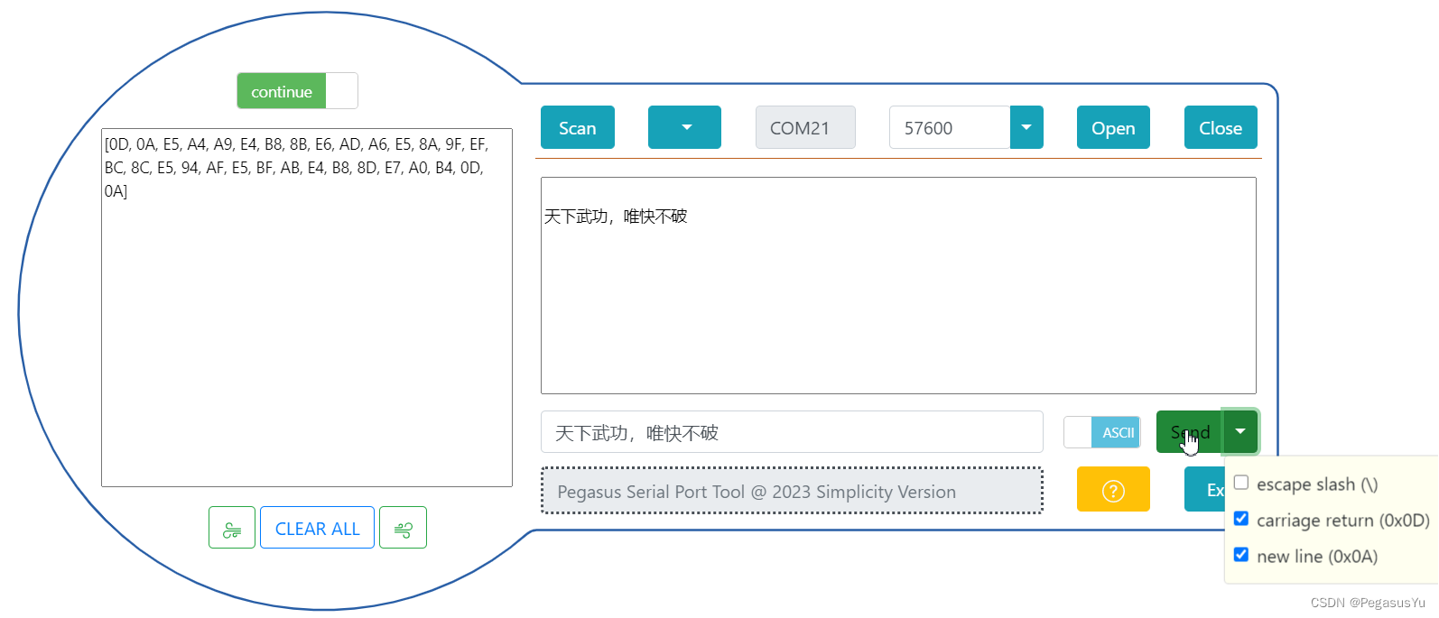
将UART1的收发管脚短接,实现环回场景并行发收测试,连接STM32的USB到PC,打开串口工具进行发收测试,效果如下:
STM32例程下载
STM32F103C6T6 USB转TTL串口例程
STM32F401CCU6 USB转TTL串口例程
扩展模式
增加UART转RS232芯片(MAX3232)电路后,也就成为了USB转RS232串口工具
也可以修改逻辑实现USB转RS422, RS485, CAN等工具
–End–
