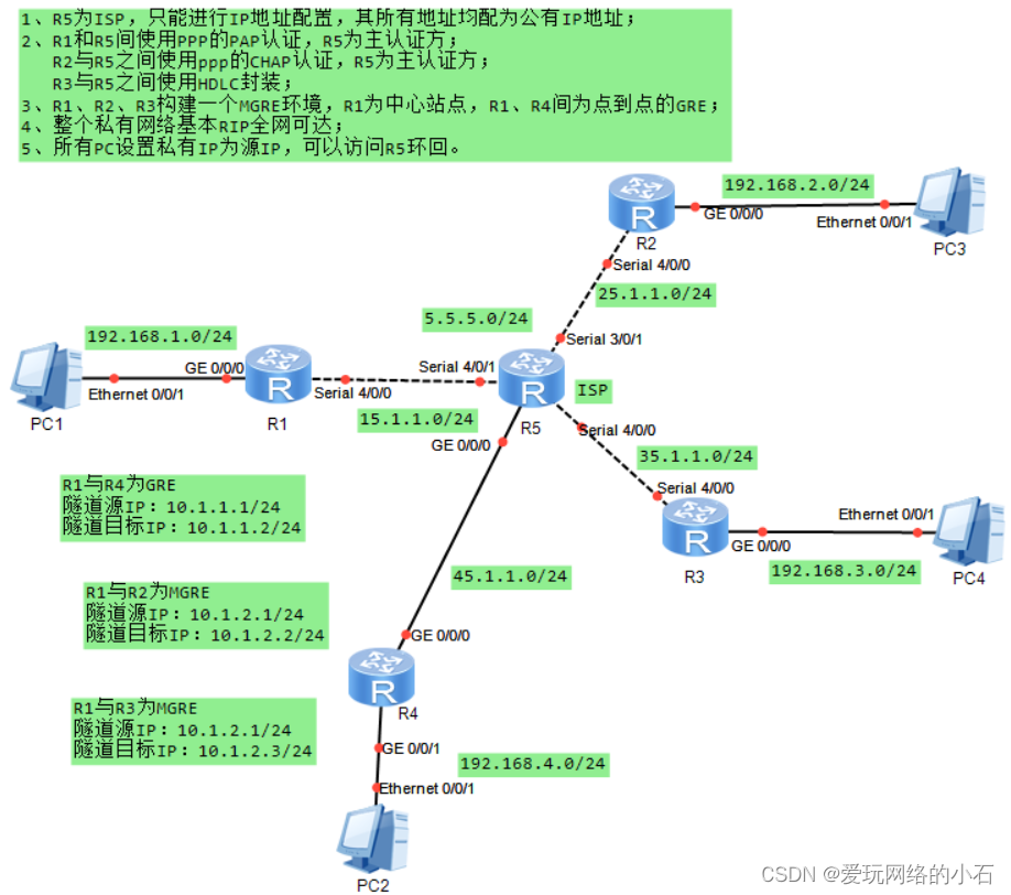
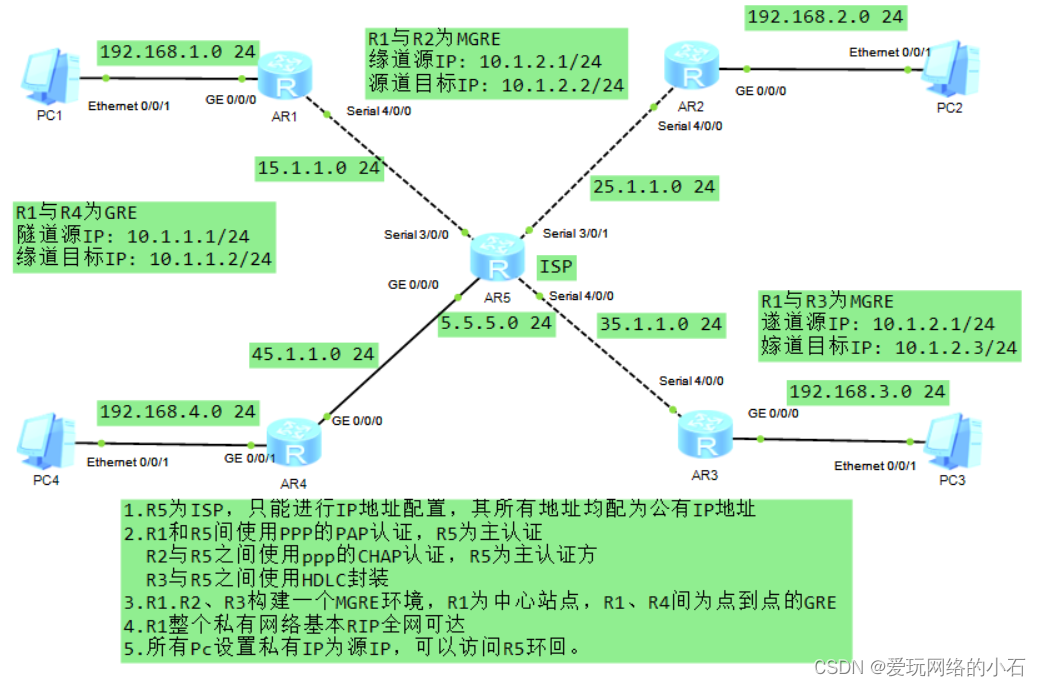
题目及视图:
实验要求:
1.R5为ISP,只能进行IP地址配置,其所有地址均配为公有IP地址
2.R1和R5间使用PPP的PAP认证,R5为主认证
R2与R5之间使用ppp的CHAP认证,R5为主认证方
R3与R5之间使用HDLC封装
3.R1.R2、R3构建一个MGRE环境,R1为中心站点,R1、R4间为点到点的GRE
4.R1整个私有网络基本RIP全网可达
5.所有Pc设置私有IP为源IP,可以访问R5环回。
实验步骤:
第一步:设计思路:
1. 由(1)知:R5 为ISP则在地址规划时,应注意公私网的区分。
2.
第二步:搭建拓扑及IP地址的规划
IP地址的规划:
路由器IP地址如拓扑图中所示。
PC地址规划如下:
PC1 192.168.1.2/24 网关 192.168.1.1/24 PC2 192.168.2.2/24 网关 192.168.2.1/24 PC3 192.168.3.2/24 网关 192.168.3.1/24 PC4 192.168.4.2/24 网关 192.168.4.1/24
第三步:配置命令
1. IP地址配置
配置R1:
<Huawei>system-view
[Huawei]sy R1
[R1]int g 0/0/0
[R1-GigabitEthernet0/0/0]ip add 192.168.1.1 24
[R1-GigabitEthernet0/0/0]int s 4/0/0
[R1-Serial4/0/0]ip add 15.1.1.1 24
配置R2:
<Huawei>system-view
[Huawei]sy R2
[R2]INT G 0/0/0
[R2-GigabitEthernet0/0/0]IP ADD 192.168.2.1 24
[R2-GigabitEthernet0/0/0]INT s 4/0/0
[R2-Serial4/0/0]ip add 25.1.1.1 24
配置R3:
<Huawei>system-view
[Huawei]sy R3
[R3]int g 0/0/0
[R3-GigabitEthernet0/0/0]ip add 192.168.3.1 24
[R3-GigabitEthernet0/0/0]int s 4/0/0
[R3-Serial4/0/0]ip add 35.1.1.1 24
配置R4:
<Huawei>sy
[Huawei]sy R4
[R4]int g 0/0/0
[R4-GigabitEthernet0/0/0]ip add 45.1.1.1 24
[R4-GigabitEthernet0/0/0]int g 0/0/1
[R4-GigabitEthernet0/0/1]ip add 192.168.4.1 24
配置R5:
<Huawei>system-view
[Huawei]sy R5
[R5]INT S 3/0/0
[R5-Serial3/0/0]IP ADD 15.1.1.2 24
[R5-Serial3/0/0]int s 3/0/1
[R5-Serial3/0/1]ip add 25.1.1.2 24
[R5-Serial3/0/1]int s 4/0/0
[R5-Serial4/0/0]ip add 35.1.1.2 24
[R5-Serial4/0/0]int g 0/0/0
[R5-GigabitEthernet0/0/0]ip add 45.1.1.2 24
[R5-GigabitEthernet0/0/0]q
[R5]int l 0
[R5-LoopBack0]ip add 5.5.5.5 24
2.缺省路由配置
[R1]ip route-static 0.0.0.0 0 15.1.1.2
[R2]ip route-static 0.0.0.0 0 25.1.1.2
[R3]ip route-static 0.0.0.0 0 35.1.1.2
[R4]ip route-static 0.0.0.0 0 45.1.1.2
3.NAT配置
配置R1:
[R1]acl 2000
[R1-acl-basic-2000]rule 1 permit source any
[R1]INT S 4/0/0
[R1-Serial4/0/0]nat outbound 2000
配置R2:
[R2]ACL 2000
[R2-acl-basic-2000]rule 1 permit source any
[R2-acl-basic-2000]q
[R2]int s 4/0/0
[R2-Serial4/0/0]nat outbound 2000
配置R3:
[R3]acl 2000
[R3-acl-basic-2000]rule 1 permit source any
[R3-acl-basic-2000]q
[R3]int s 4/0/0
[R3-Serial4/0/0]nat outbound 2000
配置R4:
[R4]acl 2000
[R4-acl-basic-2000]rule 1 permit source any
[R4-acl-basic-2000]q
[R4]int g 0/0/0
[R4-GigabitEthernet0/0/0]nat outbound 2000
4. 配置PAP认证
认证方配置
[R5]aaa                                             # 进入aaa模式
[R5-aaa]local-user huawei password cipher 123456    # 创建认证端账户huawei,密码为123456
[R5-aaa]local-user  huawei service-type ppp         # 此账户只允许被ppp协议使用
[R5]int s 3/0/0
[R5-Serial3/0/0]ppp authentication-mode pap         # 启用ppp协议中的chap协议认证
[R5-Serial3/0/0]link-protocol ppp                   # 串口接口使用ppp协议
被认证方配置
R1配置
[R1]int s 4/0/0
[R1-Serial4/0/0]link-protocol ppp     # 串口接口使用PPP协议
[R1-Serial4/0/0]ppp pap local-user huawei password cipher 123456
#  输入认证端账户密码
5. 配置CHAP认证
认证方配置
[R5]aaa
[R5-aaa]local-user huawei password cipher 123456
[R5-aaa]local-user huawie service-type ppp
[R5-aaa]q
[R5]int s 3/0/1
[R5-Serial3/0/1]link-protocol ppp
[R5-Serial3/0/1]ppp authentication-mode chap
[R5-Serial3/0/1]
被认证方配置
[R2]int s 4/0/0
[R2-Serial4/0/0]ppp chap user huawie
[R2-Serial4/0/0]ppp chap password cipher 123456
6. HDLC封装
[R5]interface Serial 4/0/0
[R5-Serial4/0/0]link-protocol hdlc
[R3]int Serial 4/0/0
[R3-Serial4/0/0]link-protocol hdlc 7. R1R2R3构建MGRE环境
中心站点R1配置:
[R1]display nhrp peer all 查看nhrp注册情况
[R1]int Tunnel 0/0/0                       # 创建隧道口
[R1-Tunnel0/0/0]ip add 10.1.1.1 24         # 为隧道配置IP地址
[R1-Tunnel0/0/0]tunnel-protocol gre p2mp   # 修改接口模式为多点GRE模式
[R1-Tunnel0/0/0]source 15.1.1.1            # 定义公有封装源
[R1-Tunnel0/0/0]nhrp network-id 100        # 创建域ID
分支占点
R2配置
[R2]int t 0/0/0
[R2-Tunnel0/0/0]ip add 10.1.1.2 24
[R2-Tunnel0/0/0]tunnel-protocol gre p2mp
[R2-Tunnel0/0/0]source S4/0/0                          # 假设分支站点的IP地址是不固定的
[R2-Tunnel0/0/0]nhrp entry 10.1.1.1 15.1.1.1 register  # 分支需要到中心站点注册
                         #  隧道地址 物理地址   注册
[R2-Tunnel0/0/0]nhrp network-id 100
R3配置
[R3]int  t 0/0/0
[R3-Tunnel0/0/0]ip add 10.1.1.3 24
[R3-Tunnel0/0/0]tunnel-protocol gre p2mp
[R3-Tunnel0/0/0]source s 4/0/0
[R3-Tunnel0/0/0]nhrp entry 10.1.1.1 15.1.1.1 register
[R3-Tunnel0/0/0]nhrp network-id 100
8. 配置GRE
R1配置
[R1]int t 0/0/1
[R1-Tunnel0/0/1]ip add 2.1.1.1 24
[R1-Tunnel0/0/1]tunnel-protocol gre
[R1-Tunnel0/0/1]source 15.1.1.1
[R1-Tunnel0/0/1]destination 45.1.1.1
R4配置
[R4]int t 0/0/1
[R4-Tunnel0/0/1]ip add 20.1.1.2 24
[R4-Tunnel0/0/1]tunnel-protocol gre
[R4-Tunnel0/0/1]source 45.1.1.1
[R4-Tunnel0/0/1]destination 15.1.1.1
9. 配置RIP路由
MGRE环境下RIP路由配置
R1配置
[R1]rip 1
[R1-rip-1]version 2
[R1-rip-1]network 192.168.1.0
[R1-rip-1]network 10.0.0.0
注意:MGRE环境下RIP需要开启伪⼴播和关闭⽔平分割
[R1]int t 0/0/0
[R1-Tunnel0/0/0]nhrp entry multicast dynamic    #开启伪广播域
[R1-Tunnel0/0/0]undo rip split-horizon          #关闭水平分割
R2配置
[R2]rip 1
[R2-rip-1]version 2
[R2-rip-1]network 192.168.2.0
[R2-rip-1]network 10.0.0.0
R3配置
[R3]rip 1
[R3-rip-1]version 2
[R3-rip-1]network 192.168.3.0
[R3-rip-1]network 10.0.0.0
GRE环境下RIP路由配置
R1配置
[R1]rip 1
[R1-rip-1]version 2
[R1-rip-1]network 20.0.0.0
R4配置
[R4]rip 1
[R4-rip-1]version 2
[R4-rip-1]network 20.0.0.0
[R4-rip-1]network 192.168.4.0
10. 测试
测试一:用设备PC1去pingPC4
PC>ping 192.168.4.2

Ping 192.168.4.2: 32 data bytes, Press Ctrl_C to break
Request timeout!
From 192.168.4.2: bytes=32 seq=2 ttl=126 time=31 ms
From 192.168.4.2: bytes=32 seq=3 ttl=126 time=31 ms
From 192.168.4.2: bytes=32 seq=4 ttl=126 time=31 ms
From 192.168.4.2: bytes=32 seq=5 ttl=126 time=32 ms

--- 192.168.4.2 ping statistics ---
  5 packet(s) transmitted
  4 packet(s) received
  20.00% packet loss
  round-trip min/avg/max = 0/31/32 ms
测试二:用设备PC1去pingPC2
PC>ping 192.168.3.2

Ping 192.168.3.2: 32 data bytes, Press Ctrl_C to break
Request timeout!
From 192.168.3.2: bytes=32 seq=2 ttl=126 time=31 ms
From 192.168.3.2: bytes=32 seq=3 ttl=126 time=32 ms
From 192.168.3.2: bytes=32 seq=4 ttl=126 time=31 ms
From 192.168.3.2: bytes=32 seq=5 ttl=126 time=16 ms

--- 192.168.3.2 ping statistics ---
  5 packet(s) transmitted
  4 packet(s) received
  20.00% packet loss
  round-trip min/avg/max = 0/27/32 ms
11.抓包
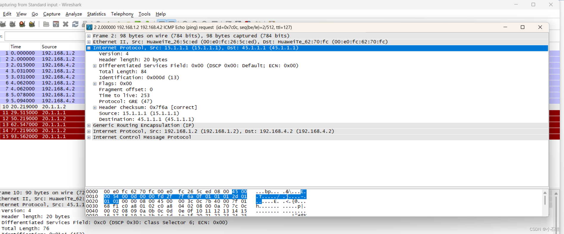
抓包测试一:抓PC4 的接口
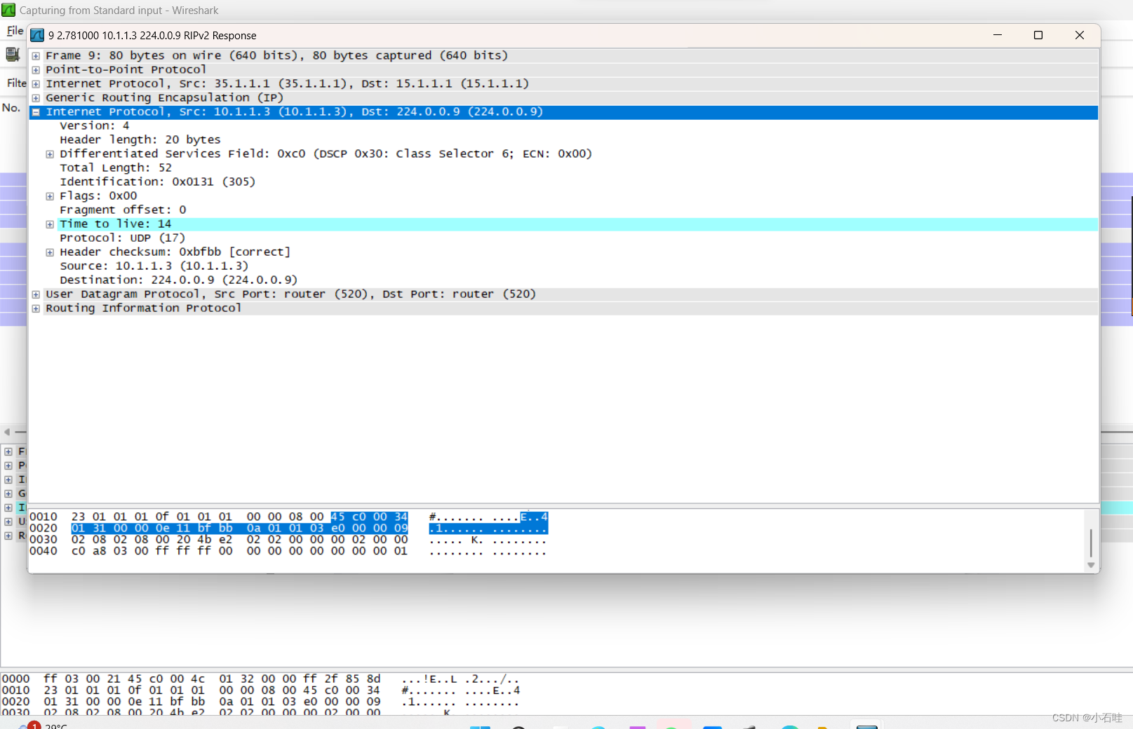
抓包测试二:抓PC3 的接口






![[Spring] SpringBoot2 简介(一)—— 基础配置](https://img-blog.csdnimg.cn/4f342c1f34384d9a8fee0f12b8b00391.png)
![[AUTOSAR][诊断管理][$10] 会话模式控制](https://img-blog.csdnimg.cn/e407f5754ea941f9a34d29c83555b82b.png)