文章目录
- 前言
- 一、下载u8g2源文件
- 二、复制和更改文件
- 2.1 复制文件
- 2.2 修改文件
- u8g2_d_setup文件
- u8g2_d_memory
- 三、编写oled.c和oled.h文件
- 3.1 CubeMX配置I2C
- 3.2 编写文件
- oled.h
- oled.c
- 四、测试代码
- main函数测试代码
- 总结
前言
在本文中,我们将介绍如何在STM32上成功地移植u8g2图形库,以便能够轻松地控制OLED或LCD显示屏。u8g2库提供了一个灵活、功能强大的框架,可以简化图形界面的开发过程。通过合理地配置STM32 CubeMX以及适当的硬件连接,我们可以使得u8g2与STM32微控制器完美结合。
我们将逐步引导您完成整个移植过程,从STM32 CubeMX的项目创建,到u8g2库的集成和配置,最终实现一个简单的示例程序,以确保整个过程的顺利进行。让我们一起开始吧!
一、下载u8g2源文件
u8g2下载地址
如果进不去可以私信我。找我要源代码。
下载好之后解压出来
二、复制和更改文件
2.1 复制文件
1、首先,在工程下面创建一个u8g2文件夹
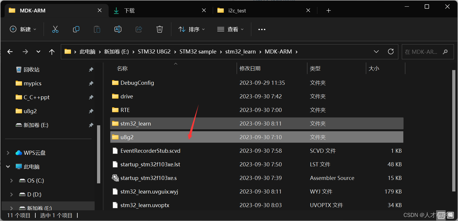
2、把我们下载好的u8g2文件夹里面的csrc下图中的这些文件复制进去

3、在工程中创建一个drive文件夹,里面放oled文件夹,oled文件夹放oled.c和oled.h,之后有用

4、打开keil,把前面的这些文件放进去

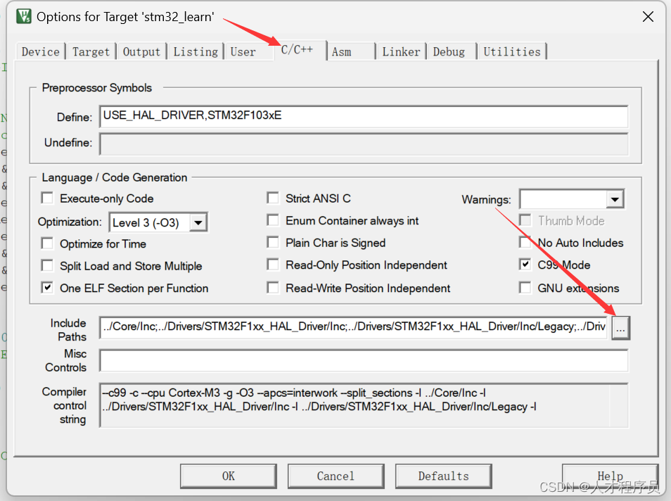
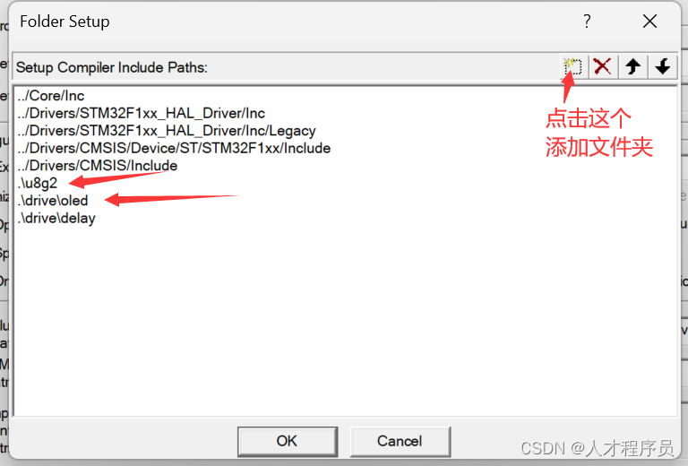

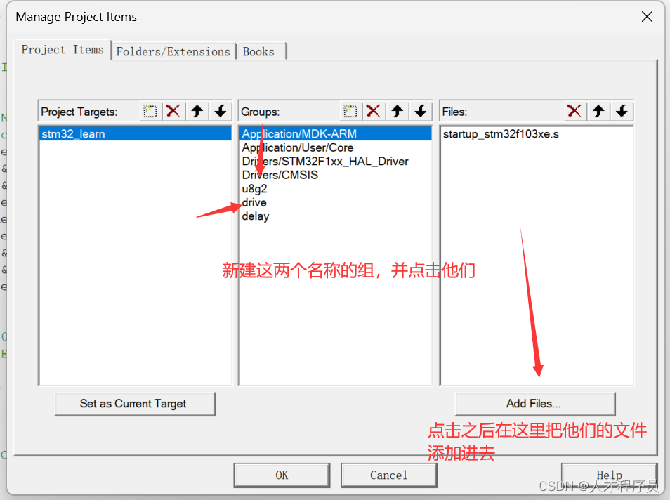
2.2 修改文件
u8g2_d_setup文件
我们需要找到下面这个函数:
void u8g2_Setup_ssd1306_i2c_128x64_noname_f(u8g2_t *u8g2, const u8g2_cb_t *rotation, u8x8_msg_cb byte_cb, u8x8_msg_cb gpio_and_delay_cb)
{
  uint8_t tile_buf_height;
  uint8_t *buf;
  u8g2_SetupDisplay(u8g2, u8x8_d_ssd1306_128x64_noname, u8x8_cad_ssd13xx_fast_i2c, byte_cb, gpio_and_delay_cb);
  buf = u8g2_m_16_8_f(&tile_buf_height);
  u8g2_SetupBuffer(u8g2, buf, tile_buf_height, u8g2_ll_hvline_vertical_top_lsb, rotation);
}
然后把其他函数给删除或者注释掉。
u8g2_d_memory
我们需要找到下面这个函数
uint8_t *u8g2_m_16_8_f(uint8_t *page_cnt)
{
  #ifdef U8G2_USE_DYNAMIC_ALLOC
  *page_cnt = 8;
  return 0;
  #else
  static uint8_t buf[1024];
  *page_cnt = 8;
  return buf;
  #endif
}
把其他函数删除或注释掉.
三、编写oled.c和oled.h文件
3.1 CubeMX配置I2C
首先我们在CubeMX配置好我们的I2C,这个在之前的文章已经讲过了,这里不多赘述。
3.2 编写文件
oled.h
我们在oled.h文件里面,把下面的代码复制进去就可以了
#ifndef __oled_H
#define __oled_H
#ifdef __cplusplus
 extern "C" {
#endif

/* Includes ------------------------------------------------------------------*/
#include "main.h"
#include "u8g2.h"
/* USER CODE BEGIN Includes */

/* USER CODE END Includes */


/* USER CODE BEGIN Private defines */

/* USER CODE END Private defines */
#define u8         unsigned char  // ?unsigned char ????
#define MAX_LEN    128  //
#define OLED_ADDRESS  0x78 // oled??????
#define OLED_CMD   0x00  // ???
#define OLED_DATA  0x40  // ???

/* USER CODE BEGIN Prototypes */
 uint8_t u8x8_byte_hw_i2c(u8x8_t *u8x8, uint8_t msg, uint8_t arg_int, void *arg_ptr);
 uint8_t u8x8_gpio_and_delay(u8x8_t *u8x8, uint8_t msg, uint8_t arg_int, void *arg_ptr);
 void u8g2Init(u8g2_t *u8g2);
 #ifdef __cplusplus
}
#endif
#endif /*__ i2c_H */
/* USER CODE END Prototypes */
oled.c
我们需要把MX_I2C1_Init,这个函数复制进去,这个函数是CubeMX生成的不需要我们自己写,如果你的函数名和我的不同,那就把u8x8_byte_hw_i2c里面的MX_I2C1_Init替换成你的函数
#include "stm32f1xx_hal.h"
#include "u8g2.h"
#include "oled.h"
#include "delay.h"
#include "main.h"
#include "oled.h"

I2C_HandleTypeDef hi2c1;

static void MX_I2C1_Init(void)
{

  /* USER CODE BEGIN I2C1_Init 0 */

  /* USER CODE END I2C1_Init 0 */

  /* USER CODE BEGIN I2C1_Init 1 */

  /* USER CODE END I2C1_Init 1 */
  hi2c1.Instance = I2C1;
  hi2c1.Init.ClockSpeed = 400000;
  hi2c1.Init.DutyCycle = I2C_DUTYCYCLE_2;
  hi2c1.Init.OwnAddress1 = 0;
  hi2c1.Init.AddressingMode = I2C_ADDRESSINGMODE_7BIT;
  hi2c1.Init.DualAddressMode = I2C_DUALADDRESS_DISABLE;
  hi2c1.Init.OwnAddress2 = 0;
  hi2c1.Init.GeneralCallMode = I2C_GENERALCALL_DISABLE;
  hi2c1.Init.NoStretchMode = I2C_NOSTRETCH_DISABLE;
  if (HAL_I2C_Init(&hi2c1) != HAL_OK)
  {
    Error_Handler();
  }
  /* USER CODE BEGIN I2C1_Init 2 */

  /* USER CODE END I2C1_Init 2 */

}

uint8_t u8x8_byte_hw_i2c(u8x8_t *u8x8, uint8_t msg, uint8_t arg_int, void *arg_ptr)
{
    /* u8g2/u8x8 will never send more than 32 bytes between START_TRANSFER and END_TRANSFER */
    static uint8_t buffer[128];
    static uint8_t buf_idx;
    uint8_t *data;

    switch (msg)
    {
    case U8X8_MSG_BYTE_INIT:
    {
        /* add your custom code to init i2c subsystem */
        MX_I2C1_Init(); //I2C???
    }
    break;

    case U8X8_MSG_BYTE_START_TRANSFER:
    {
        buf_idx = 0;
    }
    break;

    case U8X8_MSG_BYTE_SEND:
    {
        data = (uint8_t *)arg_ptr;

        while (arg_int > 0)
        {
            buffer[buf_idx++] = *data;
            data++;
            arg_int--;
        }
    }
    break;

    case U8X8_MSG_BYTE_END_TRANSFER:
    {
        if (HAL_I2C_Master_Transmit(&hi2c1, (OLED_ADDRESS), buffer, buf_idx, 1000) != HAL_OK)
            return 0;
    }
    break;

    case U8X8_MSG_BYTE_SET_DC:
        break;

    default:
        return 0;
    }

    return 1;
}

void delay_us(uint32_t time)
{
    uint32_t i = 8 * time;
    while (i--)
        ;
}

uint8_t u8x8_gpio_and_delay(u8x8_t *u8x8, uint8_t msg, uint8_t arg_int, void *arg_ptr)
{
    switch (msg)
    {
    case U8X8_MSG_DELAY_100NANO: // delay arg_int * 100 nano seconds
        __NOP();
        break;
    case U8X8_MSG_DELAY_10MICRO: // delay arg_int * 10 micro seconds
        for (uint16_t n = 0; n < 320; n++)
        {
            __NOP();
        }
        break;
    case U8X8_MSG_DELAY_MILLI: // delay arg_int * 1 milli second
        HAL_Delay(1);
        break;
    case U8X8_MSG_DELAY_I2C: // arg_int is the I2C speed in 100KHz, e.g. 4 = 400 KHz
        delay_us(5);
        break;                    // arg_int=1: delay by 5us, arg_int = 4: delay by 1.25us
    case U8X8_MSG_GPIO_I2C_CLOCK: // arg_int=0: Output low at I2C clock pin
        break;                    // arg_int=1: Input dir with pullup high for I2C clock pin
    case U8X8_MSG_GPIO_I2C_DATA:  // arg_int=0: Output low at I2C data pin
        break;                    // arg_int=1: Input dir with pullup high for I2C data pin
    case U8X8_MSG_GPIO_MENU_SELECT:
        u8x8_SetGPIOResult(u8x8, /* get menu select pin state */ 0);
        break;
    case U8X8_MSG_GPIO_MENU_NEXT:
        u8x8_SetGPIOResult(u8x8, /* get menu next pin state */ 0);
        break;
    case U8X8_MSG_GPIO_MENU_PREV:
        u8x8_SetGPIOResult(u8x8, /* get menu prev pin state */ 0);
        break;
    case U8X8_MSG_GPIO_MENU_HOME:
        u8x8_SetGPIOResult(u8x8, /* get menu home pin state */ 0);
        break;
    default:
        u8x8_SetGPIOResult(u8x8, 1); // default return value
        break;
    }
    return 1;
}
void u8g2Init(u8g2_t *u8g2)
{
	u8g2_Setup_ssd1306_i2c_128x64_noname_f(u8g2, U8G2_R0, u8x8_byte_hw_i2c, u8x8_gpio_and_delay); // ??? u8g2 ???
	u8g2_InitDisplay(u8g2);                                                                       // ??????????????,??????,?????????
	u8g2_SetPowerSave(u8g2, 0);                                                                   // ?????
	u8g2_ClearBuffer(u8g2);
}
四、测试代码
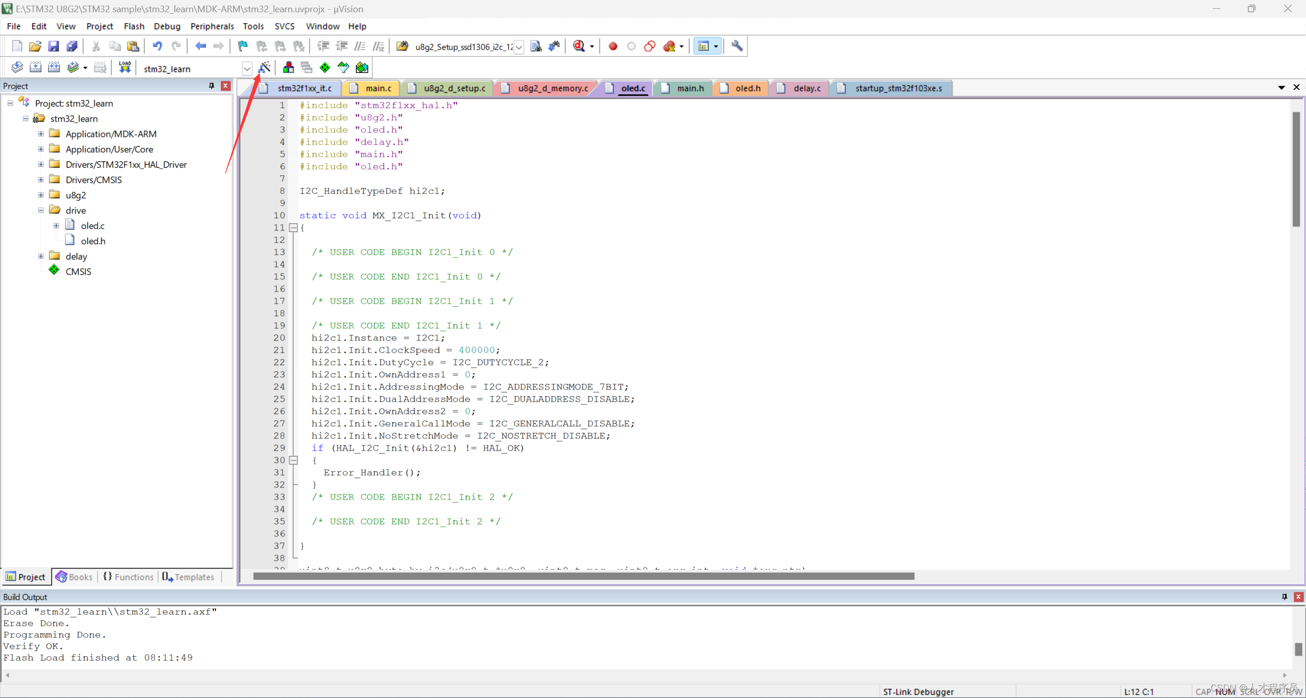
到这里已经大功告成了,最后我们需要设置一下为C99标准:

main函数测试代码
/* USER CODE BEGIN Header */
/**
  ******************************************************************************
  * @file           : main.c
  * @brief          : Main program body
  ******************************************************************************
  * @attention
  *
  * Copyright (c) 2023 STMicroelectronics.
  * All rights reserved.
  *
  * This software is licensed under terms that can be found in the LICENSE file
  * in the root directory of this software component.
  * If no LICENSE file comes with this software, it is provided AS-IS.
  *
  ******************************************************************************
  */
/* USER CODE END Header */
/* Includes ------------------------------------------------------------------*/
#include "main.h"

/* Private includes ----------------------------------------------------------*/
/* USER CODE BEGIN Includes */

#include "u8g2.h"
#include "oled.h"

/* USER CODE END Includes */

/* Private typedef -----------------------------------------------------------*/
/* USER CODE BEGIN PTD */

/* USER CODE END PTD */

/* Private define ------------------------------------------------------------*/
/* USER CODE BEGIN PD */
/* USER CODE END PD */

/* Private macro -------------------------------------------------------------*/
/* USER CODE BEGIN PM */

/* USER CODE END PM */

/* Private variables ---------------------------------------------------------*/

/* USER CODE BEGIN PV */

/* USER CODE END PV */

/* Private function prototypes -----------------------------------------------*/
void SystemClock_Config(void);
static void MX_GPIO_Init(void);
static void MX_I2C1_Init(void);
/* USER CODE BEGIN PFP */

/* USER CODE END PFP */

/* Private user code ---------------------------------------------------------*/
/* USER CODE BEGIN 0 */

/* USER CODE END 0 */

/**
  * @brief  The application entry point.
  * @retval int
  */
int main(void)
{
  /* USER CODE BEGIN 1 */

  /* USER CODE END 1 */

  /* MCU Configuration--------------------------------------------------------*/

  /* Reset of all peripherals, Initializes the Flash interface and the Systick. */
  HAL_Init();

  /* USER CODE BEGIN Init */

  /* USER CODE END Init */

  /* Configure the system clock */
  SystemClock_Config();

  /* USER CODE BEGIN SysInit */

  /* USER CODE END SysInit */

  /* Initialize all configured peripherals */
  MX_GPIO_Init();
  /* USER CODE BEGIN 2 */

  /* USER CODE END 2 */

  /* Infinite loop */
  /* USER CODE BEGIN WHILE */
	u8g2_t u8g2; // a structure which will contain all the data for one display
  u8g2Init(&u8g2);

  /* USER CODE END 2 */

  /* Infinite loop */
  /* USER CODE BEGIN WHILE */
  while (1)
  {
    /* USER CODE END WHILE */
	  //u8g2_DrawCircle(&u8g2, 64, 32, 30, U8G2_DRAW_ALL);
	   u8g2_SendBuffer(&u8g2);
	   u8g2_DrawBox(&u8g2,0,0,20,20);
	   u8g2_DrawBox(&u8g2,20,20,20,20);
	   u8g2_SendBuffer(&u8g2);
	   u8g2_DrawFrame(&u8g2,10,40,20,20);
	   u8g2_SendBuffer(&u8g2);
	   u8g2_SetFont(&u8g2,u8g2_font_DigitalDiscoThin_tf);
	   u8g2_DrawStr(&u8g2,30,10,"Hello World");
	   u8g2_SendBuffer(&u8g2);


	   HAL_Delay(1000);
    /* USER CODE BEGIN 3 */
  }
  /* USER CODE END 3 */
}

/**
  * @brief System Clock Configuration
  * @retval None
  */
void SystemClock_Config(void)
{
  RCC_OscInitTypeDef RCC_OscInitStruct = {0};
  RCC_ClkInitTypeDef RCC_ClkInitStruct = {0};

  /** Initializes the RCC Oscillators according to the specified parameters
  * in the RCC_OscInitTypeDef structure.
  */
  RCC_OscInitStruct.OscillatorType = RCC_OSCILLATORTYPE_HSE;
  RCC_OscInitStruct.HSEState = RCC_HSE_ON;
  RCC_OscInitStruct.HSEPredivValue = RCC_HSE_PREDIV_DIV1;
  RCC_OscInitStruct.HSIState = RCC_HSI_ON;
  RCC_OscInitStruct.PLL.PLLState = RCC_PLL_ON;
  RCC_OscInitStruct.PLL.PLLSource = RCC_PLLSOURCE_HSE;
  RCC_OscInitStruct.PLL.PLLMUL = RCC_PLL_MUL9;
  if (HAL_RCC_OscConfig(&RCC_OscInitStruct) != HAL_OK)
  {
    Error_Handler();
  }
  /** Initializes the CPU, AHB and APB buses clocks
  */
  RCC_ClkInitStruct.ClockType = RCC_CLOCKTYPE_HCLK|RCC_CLOCKTYPE_SYSCLK
                              |RCC_CLOCKTYPE_PCLK1|RCC_CLOCKTYPE_PCLK2;
  RCC_ClkInitStruct.SYSCLKSource = RCC_SYSCLKSOURCE_PLLCLK;
  RCC_ClkInitStruct.AHBCLKDivider = RCC_SYSCLK_DIV1;
  RCC_ClkInitStruct.APB1CLKDivider = RCC_HCLK_DIV2;
  RCC_ClkInitStruct.APB2CLKDivider = RCC_HCLK_DIV1;

  if (HAL_RCC_ClockConfig(&RCC_ClkInitStruct, FLASH_LATENCY_2) != HAL_OK)
  {
    Error_Handler();
  }
}

/**
  * @brief I2C1 Initialization Function
  * @param None
  * @retval None
  */


/**
  * @brief GPIO Initialization Function
  * @param None
  * @retval None
  */
static void MX_GPIO_Init(void)
{

  /* GPIO Ports Clock Enable */
  __HAL_RCC_GPIOA_CLK_ENABLE();
  __HAL_RCC_GPIOB_CLK_ENABLE();

}

/* USER CODE BEGIN 4 */

/* USER CODE END 4 */

/**
  * @brief  This function is executed in case of error occurrence.
  * @retval None
  */
void Error_Handler(void)
{
  /* USER CODE BEGIN Error_Handler_Debug */
  /* User can add his own implementation to report the HAL error return state */
  __disable_irq();
  while (1)
  {
  }
  /* USER CODE END Error_Handler_Debug */
}

#ifdef  USE_FULL_ASSERT
/**
  * @brief  Reports the name of the source file and the source line number
  *         where the assert_param error has occurred.
  * @param  file: pointer to the source file name
  * @param  line: assert_param error line source number
  * @retval None
  */
void assert_failed(uint8_t *file, uint32_t line)
{
  /* USER CODE BEGIN 6 */
  /* User can add his own implementation to report the file name and line number,
     ex: printf("Wrong parameters value: file %s on line %d\r\n", file, line) */
  /* USER CODE END 6 */
}
#endif /* USE_FULL_ASSERT */
我们编译,烧写,即可看到oled已经显示了!
总结
通过本文的介绍与实践,我们成功地将u8g2图形库移植到了STM32微控制器上,并实现了一个简单的示例程序。以下是我们在整个过程中所取得的关键成果:
STM32 CubeMX项目创建:我们从零开始使用了STM32 CubeMX创建了一个新的项目,确保了正确的初始化和配置。
硬件连接:通过正确地连接OLED或LCD显示屏到STM32微控制器,我们保证了u8g2能够与硬件正确通信。
u8g2库的集成与配置:我们成功地将u8g2库添加到了STM32 CubeMX项目中,并配置了相关的参数,以确保适应我们的硬件需求。
示例程序的编写:我们编写了一个简单的示例程序,以验证u8g2库的正确移植与配置。
通过这个实例,我们展示了如何在STM32上成功地移植u8g2库,为您在嵌入式图形界面开发中提供了一个强大的工具。希望本文对您在此方面的工作和项目中能够提供有价值的参考。祝您的项目取得圆满成功!
![2023年中国新能源圆柱电池市场发展前景分析:新能源圆柱行业发展前景乐观向好[图]](https://img-blog.csdnimg.cn/img_convert/636c74587c35598ab2b6bea8b7024063.png)


