文章目录
- openpnp - use STM32 arduino on SchultzController
- 概述
- 笔记
- 官方的起始文档
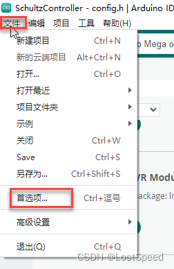
- 增加arduino第三方开发板库索引地址
- 改好后, 能编译过的工程
- SchultzController.ino
- Feeder.h
- Feeder.cpp
- 再验证一下内存是否够用
- 补充 - 如果是自己做的板子
- END
openpnp - use STM32 arduino on SchultzController
概述
我的飞达控制板用的控制主板是原装的arduino 2560 R3, MCU内存太小了, 导致52路(104位)的西门子二手飞达控制无法实现(只能控制22路(44位飞达), 否则内存受限, 编译不过去, 或者编译过去了, 运行时内存不够导致栈溢出/导致逻辑异常).
看到资料, 可以在arduino IDE中用STM32开发板, arduino工程实现不用改, 只需要选好板子, 重新编译下载, 这挺方便的.
手头有好多STM32官方的板子(大部分STM32的官方板子都支持arduino应用), 总有一款适用的, 正好整起来.
等用单独的官方开发板将工程编译过了, 剩下的事情: 查STM32官方板子的arduino引脚定义, 再画一个板子就O了.
笔记
官方的起始文档
https://github.com/stm32duino/BoardManagerFiles
https://github.com/stm32duino/Arduino_Core_STM32/wiki
有了这2个索引文档, 就可以按照说明来使用 STM32 arduino了.
STM32Arduino 社区 : http://www.stm32duino.com/
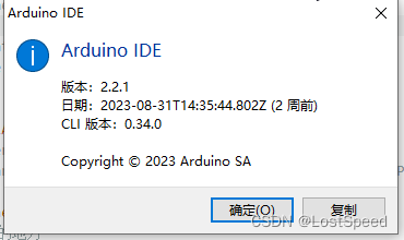
使用的arduino IDE 版本为 2.2.1
增加arduino第三方开发板库索引地址
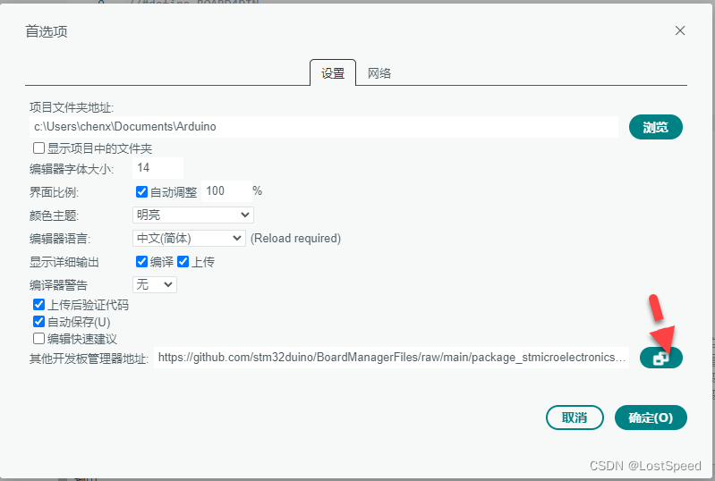
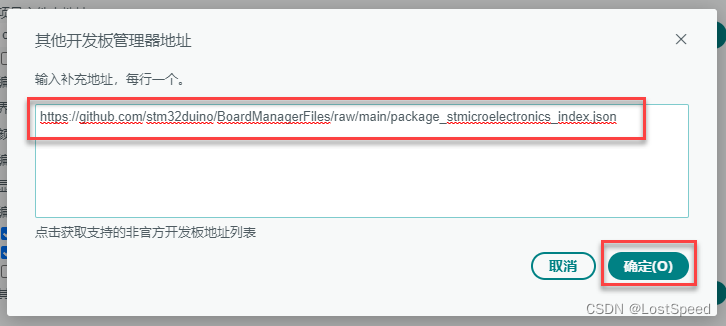
https://github.com/stm32duino/BoardManagerFiles/raw/main/package_stmicroelectronics_index.json
此时, arduinoIDE从网上的库地址, 已经将库索引下来完成.
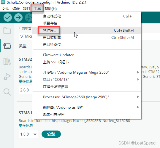
在库管理中, 查找并安装STM32Arduino的库
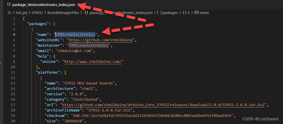
从库索引.json文件中, 可知包作者名称为 STMicroelectronics
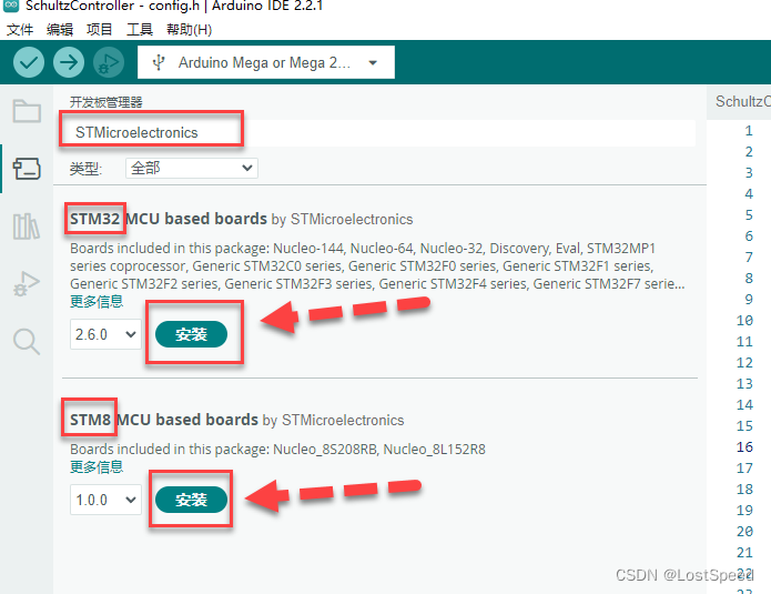
将这2个包的版本选为最新(STM32 Arduino 2.6, STM8 Arduino 1.0), STM32Arduino提供的STM32和STM8的库就一起就装上.
装的时候有点慢, 保持网络畅通.
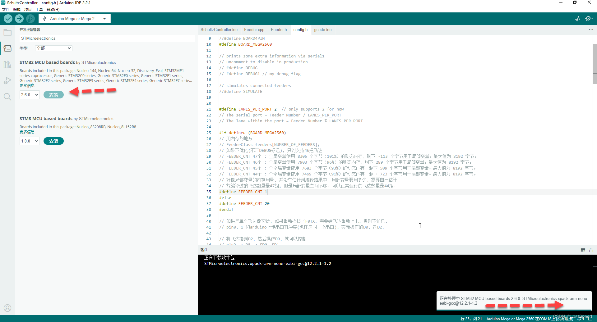
看STM32 Arduino支持的STM32官方板子中是否有自己手头的板子. https://github.com/stm32duino/Arduino_Core_STM32/wiki
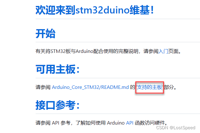
https://github.com/stm32duino/Arduino_Core_STM32/#supported-boards
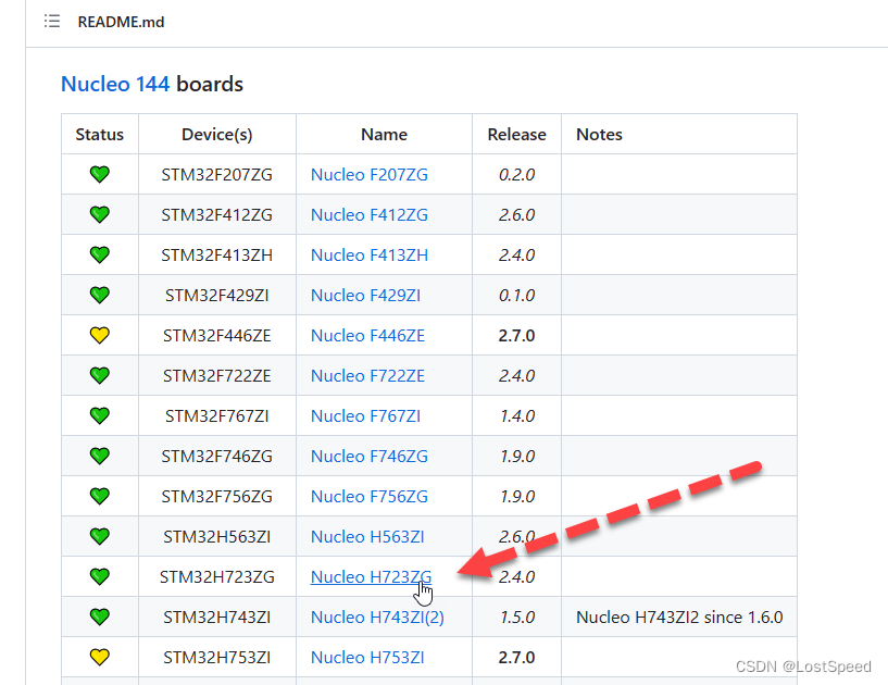
去查NUCLEO-H723ZG的官方文档, 看是否支持arduino, 是否有相关引出插座上的管脚定义 https://www.st.com/en/evaluation-tools/nucleo-h723zg.html#documentation
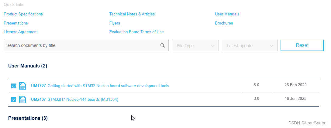
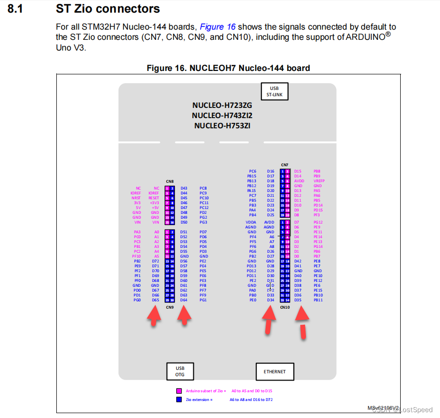
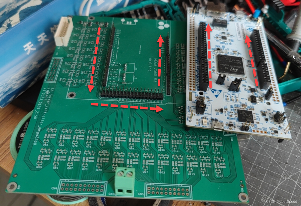
可知, NUCLEO-H723ZG支持arduino, 但是引脚外形结构引出和mega2560R3不相同, 需要重新画一个板子(引脚布局差的有点大, 如果做一块转接板, 不太好弄).
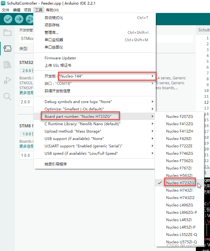
选择具体的官方开发板
尝试编译工程通过时, 不需要连接物理开发板到计算机, 等工程编译过了, 再连接物理开发板不迟.
直接编译工程, 是会报错的, 需要修改工程.
修改工程的原因:
mega2560R3是8位的主控, 数据类型包括指针都是8位的.
H7是32位的主控. 工程中用到的一些数据类型需要由uint8_t改为uint32_t.
有些函数, 是AVR独有的函数, 要添加自己的函数. e.g. 用指令周期循环做的短延时函数.
因为这个延时函数是用于IO模拟串口发送用的, 必须是算好的短延时函数, 不能是ms级别的演示.
如果是第一次玩arduino, 编译不过时的报错给人的感觉挺奇怪的. 得自己折腾, 适应几个小时, 调试的感觉就回来了.
编译报错时, 如果要加代码, 可以看arduino提供的STM32开发板的例子工程.
看STM32Arduino官方给的例子工程了(看看每个知识点的头文件包含, 调用的Arduino API).
根据报错, 将知识点用到的API换成例子中的头文件和函数调用就搞定.
Arduino比较好的一点, 例子都在IDE中有新建例子工程, 不用磁盘上到处去找.
随便打开一个NUCLEO144的例子工程.
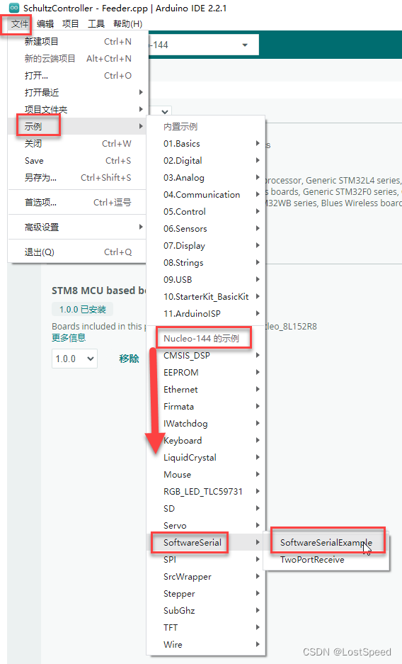
新建的例子工程, 开发板的选项和父工程相同.
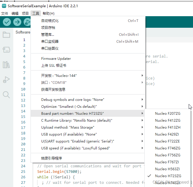
编译一下, 看看是否能通过.
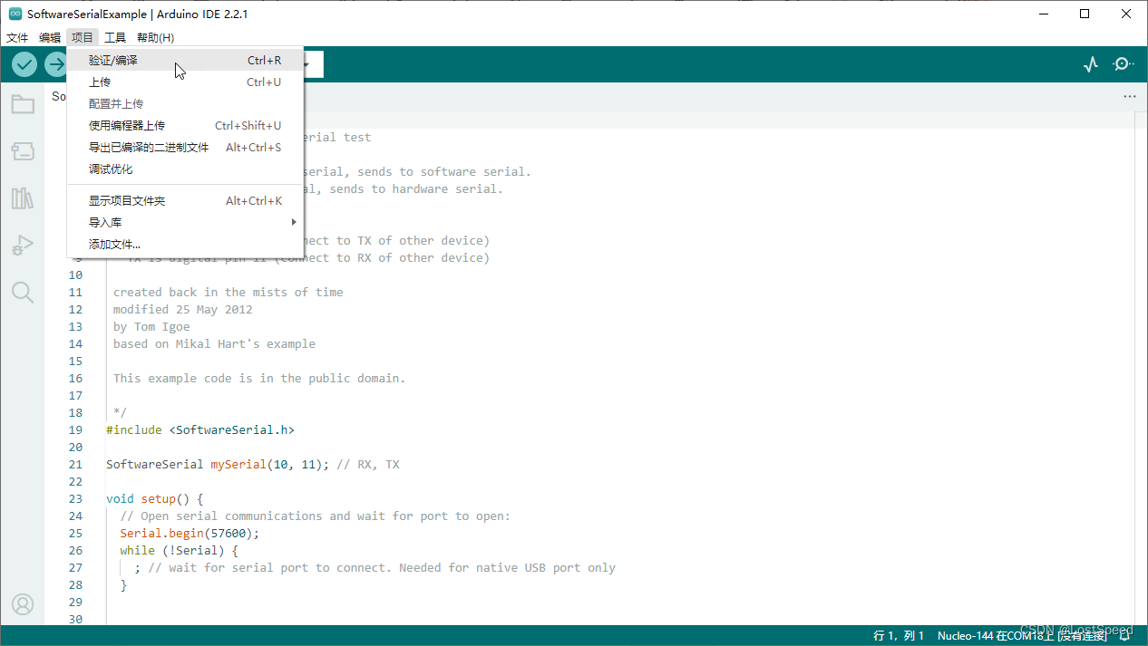
例子工程编译过了
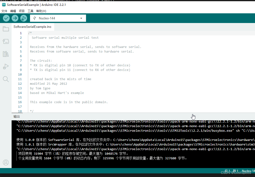
看看例子工程在磁盘哪个位置, 然后就可以用VSCode打开集中观摩学习了.
FQBN: STMicroelectronics:stm32:Nucleo_144:pnum=NUCLEO_H723ZG
使用平台的 ‘Nucleo_144’ 开发板,在列出的文件夹中:C:\Users\chenx\AppData\Local\Arduino15\packages\STMicroelectronics\hardware\stm32\2.6.0
使用平台的 ‘arduino’ 代码,在列出的文件夹中:C:\Users\chenx\AppData\Local\Arduino15\packages\STMicroelectronics\hardware\stm32\2.6.0
从例子工程的编译信息中可知, 位置如下:
C:\Users\chenx\AppData\Local\Arduino15\packages\STMicroelectronics\hardware\stm32\2.6.0
在这个目录中搜索*.ino, 找到了所有的例子工程.
C:\Users\chenx\AppData\Local\Arduino15\packages\STMicroelectronics\hardware\stm32\2.6.0\libraries
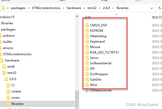
这个目录下, 每个子目录都是库, 都有对应使用的例子.
每个子目录下都有一个examples目录, 里面都是例子工程.
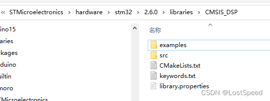


先将例子工程都过一遍(不用Arduino IDE, 用VSCode快点, 只看内容进行知识点的初步学习, 不编译).
翻了一遍例子工程, 发现工程都是一个.ino了事, 将所有例子工程都拷贝到一个临时目录
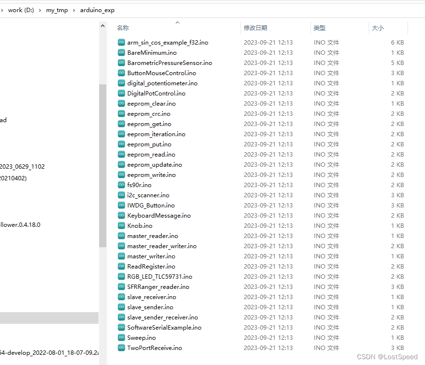
然后根据要编译的自己的原始工程的报错, 来用SI来搜索头文件和API.
现在可以编译自己工程了, 根据报错提示来更新头文件的引用.
开始尝试编译, 修正报错
工程编译过了, 将修改点, 按照git归档记录一下.
不是经常弄arduino, 看着报错信息挺怪的, 适应后就好了.
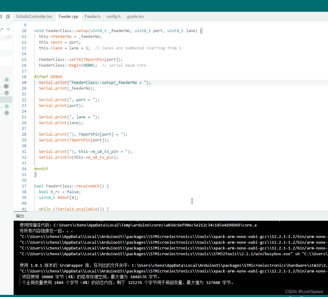
改好后, 能编译过的工程
编译过后, 一共改了3个源文件.
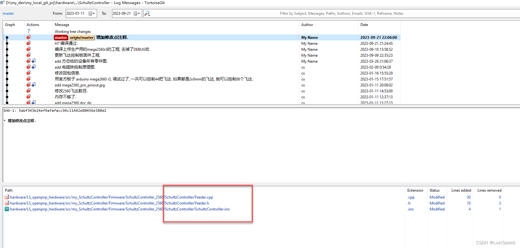
修改处加了@bugfix 标记, 方便查找, 移动改了16处代码.
修改后的3个文件内容如下:
SchultzController.ino
/*
* Author: Bill Ruckman
* (c)2020
*
* Adapted from 0816feeder by mrgl
*    https://github.com/mgrl/0816-feeder-firmware
*
* This work is licensed under a Creative Commons Attribution-NonCommercial-ShareAlike 4.0 International License.
* http://creativecommons.org/licenses/by-nc-sa/4.0/
*
* current version: v0.0
*
*
*/

// ------------------  I N C  L I B R A R I E S ---------------

#include "config.h"
#include "Feeder.h"


// ------------------  V A R  S E T U P -----------------------

FeederClass feeders[NUMBER_OF_FEEDERS];

// @bugfix 1
HardwareSerial Serial1(1); // 增加的给飞达发送指令的物理串口, 库中没有定义好的Serial1可用.

// ------------------  U T I L I T I E S ---------------


// ------------------  S E T U P -----------------------
void setup() {
  byte i;

  Serial.begin(SERIAL_BAUD);
  while (!Serial)
    ;
  Serial.println(PRJ_NAME " " PRJ_VER " "
                          "starting...");
  Serial.flush();

  // @bugfix 2
  // Serial1.begin(9600);  // The hardware RX port
  Serial1.begin(9600, SERIAL_8N1); // 这里的发送管脚不要做数字IO用了, 发送脚闲置, 只用接收引脚

  for (i = 0; i < NUMBER_OF_FEEDERS; i++) {
    feeders[i].setup(i, i / LANES_PER_PORT, i % LANES_PER_PORT);  // initialize with feeder number, port and lane
  }

  // setup listener to serial stream
  setupGCodeProc();

  Serial.println(PRJ_NAME " " PRJ_VER " "
                          "ready.");
}


// ------------------  L O O P -----------------------

void loop() {
  // Process incoming serial data and perform callbacks
  listenToSerialStream();
}
Feeder.h
#ifndef _FEEDER_h
#define _FEEDER_h

#include "arduino.h"
#include "config.h"


class FeederClass {
	protected:

			//on initialize it gets a number.
			int feederNo=-1;

			uint8_t port;	// TX serial port for this feeder
			uint8_t lane;	// lane within port
			uint8_t feederStatus = 0;	// initialized to invalid

      #ifdef SIMULATE
        uint8_t eeprom[16]; // simulates eeprom storage for read and write commands
      #endif

      /*
       *  Feeder number to TX port mapping (uses D port numbers)
       */
#if defined (BOARD96PIN)
      const uint8_t TXportPin[20] = { 12, 13, 14, 15, 16, 17, 18, 19, 20, 21, 11, 10, 9, 8, 7, 6, 5, 4, 3, 2 };
#elif defined (BOARD4PIN)
      const uint8_t TXportPin[20] = { 2, 3, 4, 5, 6, 7, 8, 9, 10, 11, 21, 20, 19, 18, 17, 16, 15, 14, 13, 12 }; // Matches ref des order of board
      //const uint8_t TXportPin[20] = { 12, 13, 14, 15, 16, 17, 18, 19, 20, 21, 2, 3, 4, 5, 6, 7, 8, 9, 10, 11 }; // J20 is port 0, then goes counter-clockwise
#elif defined (BOARD_MEGA2560)
      // 官方arduino mega2560 R3 一共有70个数字IO(D0~D69), D0/D1 被编程串口占用了不能用. 剩下的可用数字IO位68个(D2~D69)
      // 其中D14/D15 = UART3, D16/D17 = UART2, D18/D19 = UART1, 这3个串口留着调试用, 剩下的可用数字IO为62个(D2~D13, D20~D69)
const uint8_t TXportPin[FEEDER_CNT] = {
        // D2 => D31 was F1 => F30
        21, // pin = D21
        /*2,  3,  4,  5,  6,  7,  8,  9,  10, 11,
        12, 13, 20, 21, 22, 23, 24, 25, 26, 27,
        28, 29, 30, 31, 32, 33, 34, 35, 36, 37,
        38, 39, 40, 41, 42, 43, 44, 45, 46, 47,
        48, 49, 50, 51, 52, 53, 54, 55, 56, 57,
        58, 59, 60, 61, 62, 63, 64, 65, 66, 67,
        68, 69*/
        };
#else
      const uint8_t TXportPin[20] = { 2, 3, 4, 5, 6, 7, 8, 9, 10, 11, 12, 12, 14, 15, 16, 17, 18, 19, 20, 21 };
#endif

      bool inverse_logic = true;  // inverted logic for serial output

      bool sendCommand(uint8_t command);  // sends a simple command
      bool sendCommand(uint8_t command, uint8_t *dataBuf);  // sends a simple command, gets a response in dataBuf
      bool sendCommand(uint8_t command, uint8_t *dataBuf, uint8_t offset);  // sends a simple command with extra byte (offset) after lane, gets a response in dataBuf
      bool sendCommand(uint8_t command, uint8_t len, uint8_t *dataBuf);  // sends a simple command followed by data in dataBuf
      bool receiveACK();
      bool receiveMessage(uint8_t *dataBuf);

      /*
       * software serial routines - adapted from SendOnlySoftwareSerial by Nick Gammon 30th December 2016
       */

       // @bugfix 3
       // uint8_t _transmitBitMask; // 8位MCU的数据类型
      uint32_t _transmitBitMask; // 32位MCU的数据类型

      // volatile uint8_t *_transmitPortRegister;  // 8位MCU的数据类型
      volatile uint32_t *_transmitPortRegister; // 32位MCU的数据类型
      uint8_t m_u8_tx_pin; // 具体是操作核心板哪个引出的管脚

      // Expressed as 4-cycle delays (must never be 0!)
      uint16_t _tx_delay;

      // private methods
      void setTX(uint8_t transmitPin);

      // Return num - sub, or 1 if the result would be < 1
      static uint16_t subtract_cap(uint16_t num, uint16_t sub);

      // private static method for timing
      static inline void tunedDelay(uint16_t delay);

      // @bugfix 4
      static inline void _delay_loop_2(uint16_t __count); // 增加的指令周期级别的延时

	public:

    //store last timestamp command was sent for timeout
    unsigned long lastTimeCommandSent;

    void setup(uint8_t _feeder_no, uint8_t port, uint8_t lane);

    bool sendPrePick();
    bool sendAdvance(bool overrideError);
    bool setPitch(uint8_t pitch);
    bool clearFeedCount();
    bool getFeederStatus();
    bool readEEPROM(uint8_t *buf);
    bool readInfo(uint8_t *buf);
    bool startSelfTest();
    bool stopSelfTest();
    bool setID(int32_t feederID);

    String reportStatus();
    String showStatus();
    bool feederIsOk();

    //software serial
    void begin(long speed);
    virtual size_t write(uint8_t byte);
};

extern FeederClass Feeder;

#endif
Feeder.cpp
// @bugfix 5
// #include <avr/interrupt.h>

// @bugfix 6
// #include <avr/pgmspace.h>
#include <Arduino.h>

// @bugfix 7
// #include <util/delay_basic.h>

#include "Feeder.h"
#include "config.h"

void FeederClass::setup(uint8_t _feederNo, uint8_t port, uint8_t lane) {
  this->feederNo = _feederNo;
  this->port = port;
  this->lane = lane + 1;  // lanes are numbered starting from 1

  FeederClass::setTX(TXportPin[port]);
  FeederClass::begin(9600);  // serial baud rate

#ifdef DEBUG
  Serial.print("FeederClass::setup(_feederNo = ");
  Serial.print(_feederNo);

  Serial.print(", port = ");
  Serial.print(port);

  Serial.print(", lane = ");
  Serial.print(lane);

  Serial.print("), TXportPin[port] = ");
  Serial.print(TXportPin[port]);

  Serial.print("), this->m_u8_tx_pin = ");
  Serial.println(this->m_u8_tx_pin);

#endif
}

bool FeederClass::receiveACK() {
  bool b_rc = false;
  uint8_t RXbuf[4];

  while (!Serial1.available()) {
    if ((millis() - this->lastTimeCommandSent) > ACK_TIMEOUT) {
#ifdef DEBUG
      Serial.println(" ACK timeout!");
#endif
      return false;
    }
  }

  Serial1.readBytes(RXbuf, 3);

#ifdef DEBUG
  Serial.print("FeederClass::receiveACK() : recv : ");
  Serial.print(RXbuf[0], HEX);
  Serial.print(' ');
  Serial.print(RXbuf[1], HEX);
  Serial.print(' ');
  Serial.println(RXbuf[2], HEX);
#endif

  b_rc = ((RXbuf[0] == 1) && (RXbuf[1] == 0xE0) && (RXbuf[2] == 0xE1));
#ifdef DEBUG
  Serial.print("FeederClass::receiveACK() : b_rc = ");
  Serial.println(b_rc);
#endif

  return b_rc;
}

bool FeederClass::receiveMessage(uint8_t *dataBuf) {
  uint8_t RXbuf[4];
  uint8_t inChar;
  uint8_t msgLen = 0;
  uint8_t RXckSum = 0;
  bool gotError = false;

  while (!Serial1.available()) {
    if ((millis() - this->lastTimeCommandSent) > RESP_TIMEOUT) {
#ifdef DEBUG
      Serial.println(" ack timeout!");
#endif
      return false;
    }
  }

  // expecting ack message
  Serial1.readBytes(RXbuf, 3);

#ifdef DEBUG
  Serial.print("FeederClass::receiveMessage() : recv : ");
  Serial.print(RXbuf[0], HEX);
  Serial.print(' ');
  Serial.print(RXbuf[1], HEX);
  Serial.print(' ');
  Serial.println(RXbuf[2], HEX);
#endif

  gotError = (RXbuf[0] != 1) || (RXbuf[1] != 0xE0) || (RXbuf[2] != 0xE1);

  // followed by response message
  while (!Serial1.available()) {
    if ((millis() - this->lastTimeCommandSent) > RESP_TIMEOUT) {
#ifdef DEBUG
      Serial.println(" message timeout!");
#endif
      return false;
    }
  }

  // get message length
  inChar = (uint8_t)Serial1.read();
  msgLen = inChar + 1;
#ifdef DEBUG
  Serial.print("recv msgLen = ");
  Serial.println(msgLen);
#endif
  if ((msgLen > 1) && (msgLen < 64)) {  // valid message is 1 to 64 bytes, otherwise ignore it
    dataBuf[0] = inChar;                // store length
    Serial1.readBytes(&dataBuf[1], msgLen);

#ifdef DEBUG
    Serial.print("recv(HEX) : ");
    for (uint8_t i = 0; i <= msgLen; i++) {
      Serial.print(dataBuf[i], HEX);
      Serial.print(" ");
    }
    Serial.println("");
#endif

    // verify checksum
    RXckSum = 0;
    for (uint8_t i = 0; i < msgLen; i++) {
      RXckSum += dataBuf[i];
    }

    if (RXckSum != dataBuf[msgLen]) {  // verify checksum
#ifdef DEBUG
      Serial.print(dataBuf[dataBuf[0] + 1], HEX);
      Serial.print(" != ");
      Serial.print(RXckSum, HEX);
      Serial.println(" Checksum failed!");
#endif
      gotError = true;
    }
    return !gotError;
  } else {
#ifdef DEBUG
    Serial.println("err : msgLen must > 1 && < 64");
#endif
    return false;
  }
}

bool FeederClass::sendCommand(uint8_t command) {
  uint8_t cmdLen = 2;
  uint8_t buf[] = { cmdLen, command, this->lane, 0 };
  uint8_t i;
  uint8_t checksum = 0;

  while (Serial1.available()) {  // get rid of any leftover input data
    Serial1.read();
  }

  // calculate checksum
  for (i = 0; i < cmdLen + 1; i++) {
    checksum += buf[i];
  }
  buf[i] = checksum;

#ifdef DEBUG
  Serial.print("sending to port[");
  Serial.print(this->port);
  Serial.print("], m_u8_tx_pin[");
  Serial.print(m_u8_tx_pin);
  Serial.print("] =>(HEX) ");
  for (i = 0; i < cmdLen + 2; i++) {
    Serial.print(buf[i], HEX);
    Serial.print(' ');
  }
  Serial.println();
  Serial1.write(command);
#endif

#ifdef SIMULATE
  return true;
#endif
  for (i = 0; i < cmdLen + 2; i++) {
    FeederClass::write(buf[i]);
  }
  this->lastTimeCommandSent = millis();

  return FeederClass::receiveACK();
}

bool FeederClass::sendCommand(uint8_t command, uint8_t *dataBuf) {
  uint8_t cmdLen = 2;
  uint8_t buf[] = { cmdLen, command, this->lane, 0 };
  uint8_t i;
  uint8_t checksum = 0;

  while (Serial1.available()) {  // get rid of any leftover input data
    Serial1.read();
  }

  // calculate checksum
  for (i = 0; i < cmdLen + 1; i++) {
    checksum += buf[i];
  }
  buf[i] = checksum;

#ifdef DEBUG

  Serial.print("sending to port[");
  Serial.print(this->port);
  Serial.print("], m_u8_tx_pin[");
  Serial.print(m_u8_tx_pin);
  Serial.print("] =>(HEX) ");

  for (i = 0; i < cmdLen + 2; i++) {
    Serial.print(buf[i], HEX);
    Serial.print(' ');
  }
  Serial.println();
  Serial1.write(command);
#endif

#ifdef SIMULATE
  return true;
#endif
  for (i = 0; i < cmdLen + 2; i++) {
    FeederClass::write(buf[i]);
  }
  this->lastTimeCommandSent = millis();

  return FeederClass::receiveMessage(dataBuf);
}

bool FeederClass::sendCommand(uint8_t command, uint8_t *dataBuf, uint8_t offset) {
  uint8_t cmdLen = 3;
  uint8_t buf[] = { cmdLen, command, this->lane, offset, 0 };
  uint8_t i;
  uint8_t checksum = 0;

  while (Serial1.available()) {  // get rid of any leftover input data
    Serial1.read();
  }

  // calculate checksum
  for (i = 0; i < cmdLen + 1; i++) {
    checksum += buf[i];
  }
  buf[i] = checksum;

#ifdef DEBUG
  Serial.print("sending to port[");
  Serial.print(this->port);
  Serial.print("], m_u8_tx_pin[");
  Serial.print(m_u8_tx_pin);
  Serial.print("] =>(HEX) ");
  for (i = 0; i < cmdLen + 2; i++) {
    Serial.print(buf[i], HEX);
    Serial.print(' ');
  }
  Serial.println();
  Serial1.write(command);
#endif

#ifdef SIMULATE
  return true;
#endif
  for (i = 0; i < cmdLen + 2; i++) {
    FeederClass::write(buf[i]);
  }
  this->lastTimeCommandSent = millis();

  return FeederClass::receiveMessage(dataBuf);
}

bool FeederClass::sendCommand(uint8_t command, uint8_t dataLen, uint8_t *data) {
  uint8_t msgLen = dataLen + 2;
  uint8_t buf[msgLen + 2];
  uint8_t i;
  uint8_t checksum = 0;

  buf[0] = msgLen;
  buf[1] = command;
  buf[2] = this->lane;

  for (i = 0; i < dataLen; i++) {
    buf[i + 3] = data[i];
  }

  // calculate checksum
  for (i = 0; i < msgLen + 1; i++) {
    checksum += buf[i];
  }
  buf[i] = checksum;

#ifdef DEBUG
  // Serial.println(checksum, HEX);
  Serial.print("sending to port[");
  Serial.print(this->port);
  Serial.print("], m_u8_tx_pin[");
  Serial.print(m_u8_tx_pin);
  Serial.print("] =>(HEX) ");
  for (i = 0; i < msgLen + 2; i++) {
    Serial.print(buf[i], HEX);
    Serial.print(' ');
  }
  Serial.println();
#endif

  while (Serial1.available()) {  // get rid of any leftover input data
    Serial1.read();
  }

#ifdef SIMULATE
  for (i = 0; i < 16; i++) {
    this->eeprom[i] = buf[i + 3];
  }
  return true;
#endif

  for (i = 0; i < msgLen + 2; i++) {
    FeederClass::write(buf[i]);
  }
  this->lastTimeCommandSent = millis();

  return FeederClass::receiveACK();
}

bool FeederClass::sendPrePick() {
  uint8_t dataBuf[6];

#ifdef DEBUG
  Serial.println("send Pre-Pick command");
#endif

  if (!FeederClass::sendCommand(CMD_PRE_PICK, dataBuf)) {
#ifdef DEBUG
    Serial.println("No ACK from feeder");
#endif
    return false;
  }
#ifdef DEBUG
  Serial.println("Received ACK, check status");
#endif

#ifdef SIMULATE
  this->feederStatus = STATUS_OK;
#else
  this->feederStatus = dataBuf[1];  // should verify that byte 2 matches the lane?
#ifdef DEBUG
  Serial.print("feederStatus(dataBuf[1]) = 0x");
  Serial.println(this->feederStatus, HEX);
  Serial.println(this->showStatus());
#endif
#endif
  return true;
}

bool FeederClass::sendAdvance(bool overrideError) {
  if (this->feederStatus == STATUS_INVALID) {  // need to read status from feeder if it is not up to date
    FeederClass::getFeederStatus();
  }

#ifdef DEBUG
  Serial.println("advance triggered");
  Serial.println(this->showStatus());
#endif

  //check whether feeder is OK before every advance command
  if (this->feederStatus != STATUS_OK) {
    //feeder is in error state, usually this would lead to exit advance with false and no advancing command sent

    if (!overrideError) {
//error, and error was not overridden -> return false, advance not successful
#ifdef DEBUG
      Serial.println("error, and error was not overridden -> return false, advance not successful");
#endif
      return false;
    } else {
#ifdef DEBUG
      Serial.println("overridden error temporarily");
#endif
    }
  }
#ifdef DEBUG
  Serial.println("send advance command");
#endif

#ifdef SIMULATE
  if (++this->eeprom[2] == 0) ++this->eeprom[3];
#endif

  if (!FeederClass::sendCommand(CMD_ADVANCE)) {
#ifdef DEBUG
    Serial.println("No ACK from feeder");
#endif
    return false;
  }
  return true;
}

bool FeederClass::setPitch(uint8_t pitch) {
  uint8_t dataBuf[22];

  for (uint8_t i = 0; i < 22; i++) {
    dataBuf[i] = 0;
  }

#ifdef DEBUG
  Serial.print("Set pitch to ");
  Serial.println(pitch);
#endif

  dataBuf[0] = pitch;
  dataBuf[1] = 0;

  if (!FeederClass::sendCommand(CMD_SET_PITCH, 1, dataBuf)) {
#ifdef DEBUG
    Serial.println("No ACK from feeder");
#endif
    return false;
  }

  // update pitch field in eeprom
  //   Read current EEPROM data
#ifdef DEBUG
  Serial.println("1. send read EEPROM command");
#endif

  if (!FeederClass::sendCommand(CMD_EEPROM_READ, dataBuf, 0)) {
#ifdef DEBUG
    Serial.println("No ACK from feeder");
#endif
    return false;
  }

#ifdef SIMULATE
  for (uint8_t i = 0; i < 16; i++) {
    dataBuf[i + 1] = this->eeprom[i];
  }
#endif

  for (uint8_t i = 1; i < 17; i++) {
    dataBuf[i] = dataBuf[i + 3];
  }

  dataBuf[0] = 0;
  dataBuf[5] = pitch;  // pitch byte

#ifdef DEBUG
  Serial.println("send write EEPROM command");
#endif

#ifdef DEBUG
  Serial.print("EEPROM: ");
  for (uint8_t i = 0; i < 17; i++) {
    Serial.print(dataBuf[i], HEX);
    Serial.print(' ');
  }
  Serial.println();
#endif

  if (!FeederClass::sendCommand(CMD_EEPROM_WRITE, 17, dataBuf)) {
#ifdef DEBUG
    Serial.println("No ACK from feeder");
#endif
    return false;
  }

#ifdef SIMULATE
  for (uint8_t i = 0; i < 16; i++) {
    this->eeprom[i] == dataBuf[i + 1];
  }
#endif

  return true;
}

bool FeederClass::feederIsOk() {
  if (this->feederStatus == STATUS_OK) {
    return true;
  } else {
    return false;
  }
}

bool FeederClass::getFeederStatus() {
  int i = 0;
  uint8_t dataBuf[6];
#ifdef DEBUG
  Serial.println("send status command(getFeederStatus)");
#endif

  for (i = 0; i < 6; i++) {
    dataBuf[i] = 0;
  }

  if (!FeederClass::sendCommand(CMD_STATUS, dataBuf)) {
#ifdef DEBUG
    Serial.println("No ACK from feeder");
#endif
    return false;
  }

#ifdef DEBUG
  Serial.print("getFeederStatus(), ACK from feeder(HEX) : ");
  for (i = 0; i < 6; i++) {
    Serial.print(dataBuf[i], HEX);
    Serial.print(" ");
  }
  Serial.println("");


  Serial.print("feederStatus is dataBuf[1] = 0x");
  Serial.print(dataBuf[1], HEX);
  Serial.println(" ");
#endif

#ifdef SIMULATE
  this->feederStatus = STATUS_OK;
#else
  this->feederStatus = dataBuf[1];  // should verify that byte 2 matches the lane?
#endif
  return true;
}

bool FeederClass::readEEPROM(uint8_t *dataBuf) {
#ifdef DEBUG
  Serial.println("2. send read EEPROM command");
#endif

  if (!FeederClass::sendCommand(CMD_EEPROM_READ, dataBuf, 0)) {
#ifdef DEBUG
    Serial.println("No ACK from feeder");
#endif
    return false;
  }

#ifdef SIMULATE
  for (uint8_t i = 0; i < 16; i++) {
    dataBuf[i] = this->eeprom[i];
  }
#else
  uint8_t len = dataBuf[0];
  #ifdef DEBUG
    Serial.print("len = ");
    Serial.println(len);
  #endif
  uint8_t i = 0;

  // len = 2时, 没进下面这个循环
  for (; i < len - 4; i++) {
    dataBuf[i] = dataBuf[i + 4];
  }
  dataBuf[i] = 0;
#endif

  return true;
}

bool FeederClass::readInfo(uint8_t *dataBuf) {
#ifdef DEBUG
  Serial.println("send read info command");
#endif

  if (!FeederClass::sendCommand(CMD_INFO, dataBuf)) {
#ifdef DEBUG
    Serial.println("No ACK from feeder");
#endif
    return false;
  }

  return true;
}

bool FeederClass::clearFeedCount() {
  uint8_t dataBuf[22];

  // Read current EEPROM data
#ifdef DEBUG
  Serial.println("3. send read EEPROM command");
#endif

  if (!FeederClass::sendCommand(CMD_EEPROM_READ, dataBuf, 0)) {
#ifdef DEBUG
    Serial.println("No ACK from feeder");
#endif
    return false;
  }

#ifdef SIMULATE
  for (uint8_t i = 0; i < 16; i++) {
    dataBuf[i + 1] = this->eeprom[i];
  }
#endif

  for (uint8_t i = 1; i < 17; i++) {
    dataBuf[i] = dataBuf[i + 3];
  }

  dataBuf[0] = 0;

  dataBuf[3] = 0;  // count low byte
  dataBuf[4] = 0;  // count mid byte
  dataBuf[6] = 0;  // count high byte
#ifdef DEBUG
  Serial.println("send write EEPROM command");
#endif

  if (!FeederClass::sendCommand(CMD_EEPROM_WRITE, 17, dataBuf)) {
#ifdef DEBUG
    Serial.println("No ACK from feeder");
#endif
    return false;
  }

#ifdef SIMULATE
  for (uint8_t i = 0; i < 16; i++) {
    this->eeprom[i] == dataBuf[i + 1];
  }
#endif

  return true;
}

bool FeederClass::setID(int32_t feederID) {
  uint8_t dataBuf[22];

  for (uint8_t i = 0; i < 22; i++) {
    dataBuf[i] = 0;
  }

  if (this->lane == 1) {
    dataBuf[1] = feederID & 0xFF;         // low byte of ID
    dataBuf[2] = (feederID >> 8) & 0xFF;  // high byte of ID
    dataBuf[7] = 0x31;
    dataBuf[8] = 1;
  } else {
    dataBuf[8] = 0x3c;
  }

#ifdef DEBUG
  Serial.println("send write EEPROM command");
#endif

  if (!FeederClass::sendCommand(CMD_EEPROM_WRITE, 17, dataBuf)) {
#ifdef DEBUG
    Serial.println("No ACK from feeder");
#endif
    return false;
  }

#ifdef SIMULATE
  for (uint8_t i = 0; i < 16; i++) {
    this->eeprom[i] == dataBuf[i + 1];
  }
#endif

  return true;
}


String FeederClass::reportStatus() {
  FeederClass::getFeederStatus();
  return FeederClass::showStatus();
}

String FeederClass::showStatus() {
  switch (this->feederStatus) {
    case STATUS_OK:
      return "getFeederStatus: feeder OK";
      break;
    case STATUS_INVALID:
      return "getFeederStatus: invalid, status not updated";
      break;
    case STATUS_NO_TAPE_TENSION:
      return "getFeederStatus: No tape tension.  Tape may be broken";
      break;
    case STATUS_NO_TAPE_TRIGGER:
      return "getFeederStatus: Tape take-up not triggered after multiple feeds";
      break;
    case STATUS_FEED_ERROR:
      return "getFeederStatus: Feed motor did not advance";
      break;
    default:
      char statusCode[34];
      sprintf(statusCode, "Unrecognized status code %02X", this->feederStatus);
      return statusCode;
  }
}

bool FeederClass::startSelfTest() {
  uint8_t dataBuf[2];

#ifdef DEBUG
  Serial.println("send self test command");
#endif

  dataBuf[0] = 5;
  dataBuf[1] = 0;

  if (!FeederClass::sendCommand(CMD_SELF_TEST, 1, dataBuf)) {
#ifdef DEBUG
    Serial.println("No ACK from feeder");
#endif
    return false;
  } else {
    return true;
  }
}

bool FeederClass::stopSelfTest() {
  uint8_t dataBuf[2];

#ifdef DEBUG
  Serial.println("send stop self test command");
#endif

  dataBuf[0] = 7;
  dataBuf[1] = 0;

  if (!FeederClass::sendCommand(CMD_SELF_TEST, 1, dataBuf)) {
#ifdef DEBUG
    Serial.println("No ACK from feeder");
#endif
    return false;
  } else {
    return true;
  }
}

void FeederClass::setTX(uint8_t tx) {
  // First write, then set output. If we do this the other way around,
  // the pin would be output low for a short while before switching to
  // output high. Now, it is input with pullup for a short while, which
  // is fine. With inverse logic, either order is fine.
  digitalWrite(tx, this->inverse_logic ? LOW : HIGH);
  pinMode(tx, OUTPUT);
  this->_transmitBitMask = digitalPinToBitMask(tx);

  // @bugfix 8
  // uint8_t port = digitalPinToPort(tx);
  uint32_t port = (uint32_t)digitalPinToPort(tx);


  // @bugfix 9
  // this->_transmitPortRegister = portOutputRegister(port);
  this->_transmitPortRegister = portOutputRegister(((GPIO_TypeDef *)port));

  this->m_u8_tx_pin = tx;
}

uint16_t FeederClass::subtract_cap(uint16_t num, uint16_t sub) {
  if (num > sub)
    return num - sub;
  else
    return 1;
}

/* static */
inline void FeederClass::tunedDelay(uint16_t delay) {
  _delay_loop_2(delay);
}

/** \ingroup util_delay_basic

    Delay loop using a 16-bit counter \c __count, so up to 65536
    iterations are possible.  (The value 65536 would have to be
    passed as 0.)  The loop executes four CPU cycles per iteration,
    not including the overhead the compiler requires to setup the
    counter register pair.

    Thus, at a CPU speed of 1 MHz, delays of up to about 262.1
    milliseconds can be achieved.
 */
 // @bugfix 10
 // 增加的自己的指令周期级别的短延时函数
inline void FeederClass::_delay_loop_2(uint16_t __count)
{
  uint16_t loop = 0xffff;

  if (__count <= 0)
  {
    return;
  }

  do {
    // 因为用于GPIO模拟串口发送时的延时, 具体延时值, 调试时再根据实际情况决定.
    loop = 0xffff;
    do {
        __ASM( "NOP" );
    } while (--loop > 0);

  } while (--__count > 0);
}

void FeederClass::begin(long speed) {
  this->_tx_delay = 0;

  // Precalculate the various delays, in number of 4-cycle delays
  uint16_t bit_delay = (F_CPU / speed) / 4;

  // 12 (gcc 4.8.2) or 13 (gcc 4.3.2) cycles from start bit to first bit,
  // 15 (gcc 4.8.2) or 16 (gcc 4.3.2) cycles between bits,
  // 12 (gcc 4.8.2) or 14 (gcc 4.3.2) cycles from last bit to stop bit
  // These are all close enough to just use 15 cycles, since the inter-bit
  // timings are the most critical (deviations stack 8 times)
  this->_tx_delay = subtract_cap(bit_delay, 15 / 4);
}


size_t FeederClass::write(uint8_t b) {
  // By declaring these as local variables, the compiler will put them
  // in registers _before_ disabling interrupts and entering the
  // critical timing sections below, which makes it a lot easier to
  // verify the cycle timings

  // @bugfix 11
  // volatile uint8_t *reg = this->_transmitPortRegister;
  volatile uint32_t *reg = this->_transmitPortRegister;

  // @bugfix 12
  // uint8_t reg_mask = this->_transmitBitMask;
  uint32_t reg_mask = this->_transmitBitMask;

  // @bugfix 13
  // uint8_t inv_mask = ~this->_transmitBitMask;
  uint32_t inv_mask = ~this->_transmitBitMask;

  // @buffix 14
  // uint8_t oldSREG = SREG;

  bool inv = this->inverse_logic;
  uint16_t delay = this->_tx_delay;

  if (inv)
    b = ~b;

  // @bugfix 15
  // cli();  // turn off interrupts for a clean txmit
  noInterrupts();


  // Write the start bit
  if (inv)
    *reg |= reg_mask;
  else
    *reg &= inv_mask;

  tunedDelay(delay);

  // Write each of the 8 bits
  for (uint8_t i = 8; i > 0; --i) {
    if (b & 1)           // choose bit
      *reg |= reg_mask;  // send 1
    else
      *reg &= inv_mask;  // send 0

    tunedDelay(delay);
    b >>= 1;
  }

  // restore pin to natural state
  if (inv)
    *reg &= inv_mask;
  else
    *reg |= reg_mask;

  // @bugfix 16
  // SREG = oldSREG;  // turn interrupts back on
  interrupts();

  tunedDelay(delay);

  return 1;
}
再验证一下内存是否够用
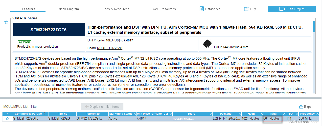
STM32H723ZGT6有564KB内存.
将飞达路数改为120, 编译一下试试.
#if defined (BOARD_MEGA2560)
// 用内存的地方
// FeederClass feeders[NUMBER_OF_FEEDERS];
// 如果不优化(不开DEBUG标记), 只能支持46把飞达
// FEEDER_CNT 47个 : 全局变量使用 8305 个字节(101%)的动态内存,剩下 -113 个字节用于局部变量。最大值为 8192 字节。
// FEEDER_CNT 46个 : 全局变量使用 7903 个字节(96%)的动态内存,剩下 289 个字节用于局部变量。最大值为 8192 字节。
// FEEDER_CNT 45个 : 个全局变量使用 7683 个字节(93%)的动态内存,剩下 509 个字节用于局部变量。最大值为 8192 字节。
// FEEDER_CNT 44个 : 个全局变量使用 7469 个字节(91%)的动态内存,剩下 723 个字节用于局部变量。最大值为 8192 字节。
// 好像局部变量的内存用量, 并没有估计到编译结果中. 局部变量要用多少, 需要自己估计.
// 能编译过的飞达数量是47组, 但是局部变量空间不够. 可以正常运行的飞达数量是44组.
#define FEEDER_CNT 120
#else
#define FEEDER_CNT 120
#endif
#elif defined (BOARD_MEGA2560)
      // 官方arduino mega2560 R3 一共有70个数字IO(D0~D69), D0/D1 被编程串口占用了不能用. 剩下的可用数字IO位68个(D2~D69)
      // 其中D14/D15 = UART3, D16/D17 = UART2, D18/D19 = UART1, 这3个串口留着调试用, 剩下的可用数字IO为62个(D2~D13, D20~D69)
const uint8_t TXportPin[FEEDER_CNT] = {
        // D2 => D31 was F1 => F30
        // 21, // pin = D21
        //
        2,  3,  4,  5,  6,  7,  8,  9,  10, 11,
        12, 13, 20, 21, 22, 23, 24, 25, 26, 27,
        28, 29, 30, 31, 32, 33, 34, 35, 36, 37,
        38, 39, 40, 41, 42, 43, 44, 45, 46, 47,
        48, 49, 50, 51, 52, 53, 54, 55, 56, 57,
        58, 59, 60, 61, 62, 63, 64, 65, 66, 67,

        2,  3,  4,  5,  6,  7,  8,  9,  10, 11,
        12, 13, 20, 21, 22, 23, 24, 25, 26, 27,
        28, 29, 30, 31, 32, 33, 34, 35, 36, 37,
        38, 39, 40, 41, 42, 43, 44, 45, 46, 47,
        48, 49, 50, 51, 52, 53, 54, 55, 56, 57,
        58, 59, 60, 61, 62, 63, 64, 65, 66, 67,
        //
        };
#else
编译结果
使用 1.0.1 版本的 SrcWrapper 库,在列出的文件夹中:C:\Users\chenx\AppData\Local\Arduino15\packages\STMicroelectronics\hardware\stm32\2.6.0\libraries\SrcWrapper
"C:\\Users\\chenx\\AppData\\Local\\Arduino15\\packages\\STMicroelectronics\\tools\\xpack-arm-none-eabi-gcc\\12.2.1-1.2/bin/arm-none-eabi-size" -A "C:\\Users\\chenx\\AppData\\Local\\Temp\\arduino\\sketches\\7D2B76A821EDD7929D88D55B655B13DD/SchultzController.ino.elf"
 项目使用 50872 字节(4%)的程序存储空间。最大值为 1048576 字节。
 个全局变量使用 37860 个字节(11%)的动态内存,剩下 289820 个字节用于局部变量。最大值为 327680 字节。
可以看到, 内存还是大大的有. 只不过, 为啥显示最大内存为327680字节? 这才320KB, 不是564KB. 是不是有一部分内存没打开.
算了, 反正对于飞达控制板应用来说, 内存足够了.
下一步, 就画一块和NUCLEO-H723ZG引出管脚配套的板子了.
具体程序实现, 是否能正常控制飞达, 等板子出来, 接上飞达再调整.
补充 - 如果是自己做的板子
官方wiki中, 也有对于只使用STM32MCU做的板子(不使用官方板子), 来使用arduino的说明.
没细看, 知道有这么个资料就行, 用到时再说.
如果是自己做的板子, 一般也就不想用arduino了(控制粒度小, 内存浪费一些).
不过要是有一块第三方的板子, 想拿来快速实验, 倒是可以参考官方的资料来让第三方的板子可以用arduino来编程, 毕竟想看效果会快一些.

