Arduino 定时器中断
Circuits Arduino
查看原文
简介:Arduino 定时器中断
奥雷里(地球、月亮和太阳)
立式兰花播种机
胶合板书柜扬声器
计时器中断允许您以非常特定的时间间隔执行任务,而不管代码中发生了什么其他事情。我将解释如何在比较匹配或 CTC 模式下以清除计时器设置和执行中断。如果要查找示例代码,请直接跳转到步骤 2。
通常,当您编写Arduino程序时,Arduino会按照编写顺序执行封装在loop( ){}函数中的所有命令,但是,很难对loop( )中的事件进行计时。有些命令比其他命令需要更长的时间来执行,有些依赖于条件语句(if,while…),一些Arduino库函数(如digitalWrite或analogRead)由许多命令组成。Arduino 定时器中断允许您以精确的时间间隔暂时暂停loop( )函数中发生的正常事件序列,同时执行一组单独的命令。完成这些命令后,Arduino 会再次从loop( )中的位置开始。
中断可用于:
- 以等间隔测量输入信号(恒定采样频率)
- 计算两个事件之间的时间
- 发送特定频率的信号定期检查传入的串行数据
更多…
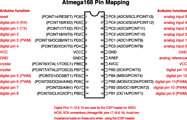
有几种方法可以进行中断,现在我将重点介绍我认为最有用/最灵活的类型,称为比较匹配或 CTC 模式下的清除计时器。这里将专门写关于[Arduino Uno ATMEL 328/168。
第 1 步:预分频器和比较匹配寄存器

Uno 有三个计时器,分别称为 timer0、timer1 和 timer2。每个计时器都有一个计数器,该计数器在计时器时钟的每个时钟周期中递增。当计数器达到存储在比较匹配寄存器中的指定值时触发CTC定时器中断,。一旦计时器计数器达到此值,它将在计时器时钟的下一个时钟周期清除(重置为零),然后它将继续再次计数到比较匹配值。通过选择比较匹配值并设置计时器递增计数器的速度,可以控制计时器中断的频率。
我将讨论的第一个参数是计时器递增计数器的速度。Arduino时钟以16MHz运行,这是计时器可以增加计数器的最快速度。在 16MHz 时,计数器的每个时钟周期表示 1/16,000,000 秒 (~63ns),因此计数器需要 10/16,000,000 秒才能达到值 9(计数器索引为 0),达到值 99 需要 100/16,000,000 秒。
在许多情况下,您会发现将计数器速度设置为 16MHz 太快了。Timer0 和 timer2 是 8 位定时器,这意味着它们可以存储最大计数器值 255。Timer1 是一个 16 位定时器,这意味着它可以存储最大计数器值 65535。一旦计数器达到最大值,它将回拨到零(这称为溢出)。这意味着在16MHz时,即使我们将比较匹配寄存器设置为最大计数器值,8位计数器每256/16,000,000秒(~16us)发生一次中断,16位计数器每65,536/16,000,000(~4毫秒)秒发生一次中断。显然,如果您只想每秒中断一次,这不是很有用。
相反,您可以使用称为预分频器的东西来控制计时器计数器增量的速度。预分频器根据以下等式指示计时器的速度:
t
i
m
e
r
s
p
e
e
d
(
H
z
)
=
A
r
d
u
i
n
o
c
l
o
c
k
s
p
e
e
d
16
M
H
z
p
r
e
s
c
a
l
e
r
timer\ speed (Hz) = \frac{Arduino\ clock\ speed\ 16MHz} {prescaler}
timer speed(Hz)=prescalerArduino clock speed 16MHz
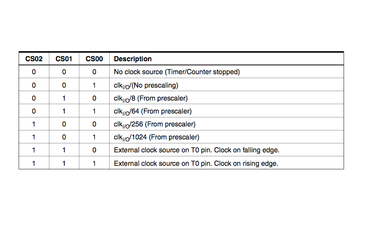
因此,1 预分频器(prescaler)将在 16MHz 时递增计数器,
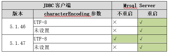
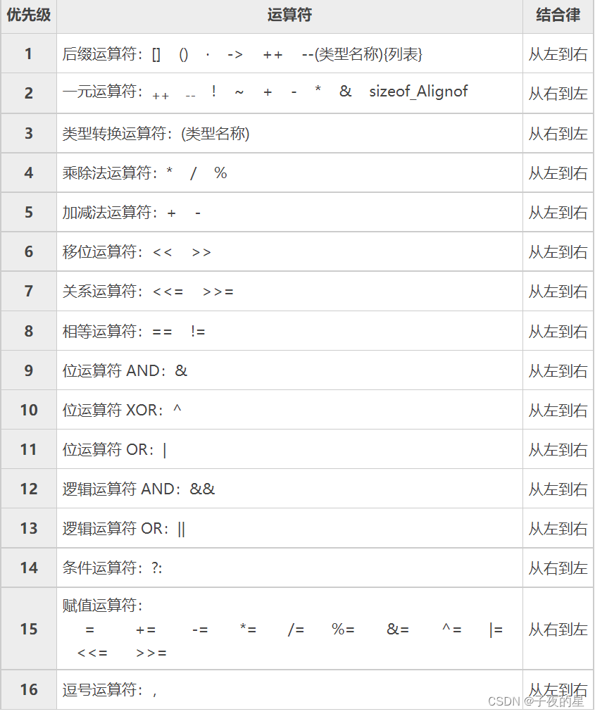
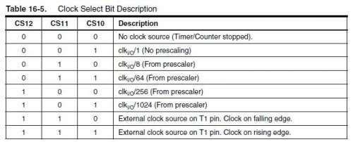
8 预分频器(prescaler)将在 2MHz 时递增计数器,64 预分频器 = 250kHz,依此类推。如上表所示,预分频器可以等于 1、8、64、256 和 1024。(我将在下一步中解释 CS12、CS11 和 CS10 的含义)。
现在您可以使用以下公式计算中断频率:
i
n
t
e
r
r
u
p
t
f
r
e
q
u
e
n
c
y
(
H
z
)
=
A
r
d
u
i
n
o
c
l
o
c
k
s
p
e
e
d
16
,
000
,
000
H
z
p
r
e
s
c
a
l
e
r
∗
(
c
o
m
p
a
r
e
m
a
t
c
h
r
e
g
i
s
t
e
r
+
1
)
interrupt\ frequency (Hz) = \frac{Arduino\ clock\ speed\ 16,000,000Hz} {prescaler * (compare\ match\ register + 1)}
interrupt frequency(Hz)=prescaler∗(compare match register+1)Arduino clock speed 16,000,000Hz
+1 是因为比较匹配寄存器是从零索引开始排列上面的等式,您可以求解比较匹配寄存器值,该值将给出您想要的中断频率:
c
o
m
p
a
r
e
m
a
t
c
h
r
e
g
i
s
t
e
r
=
16
,
000
,
000
H
z
(
p
r
e
s
c
a
l
e
r
∗
d
e
s
i
r
e
d
i
n
t
e
r
r
u
p
t
f
r
e
q
u
e
n
c
y
)
−
1
compare\ match\ register = \frac{16,000,000Hz}{(prescaler * desired\ interrupt\ frequency) } - 1
compare match register=(prescaler∗desired interrupt frequency)16,000,000Hz−1
请记住,当您使用计时器 0 和 2 时,此数字必须小于 256,计时器 1 必须小于 65536,
因此,如果您希望每秒中断一次(频率为 1Hz):
比
较
匹
配
寄
存
器
=
[
16
,
000
,
000
/
(
预
分
频
器
∗
1
)
]
−
1
比较匹配寄存器 = [16,000,000 / (预分频器 * 1) ] -1
比较匹配寄存器=[16,000,000/(预分频器∗1)]−1
,预分频器为 1024,您将获得:
比
较
匹
配
寄
存
器
=
[
16
,
000
,
000
/
(
1024
∗
1
)
]
−
1
比较匹配寄存器 = [16,000,000 / (1024* 1) ] -1
比较匹配寄存器=[16,000,000/(1024∗1)]−1
由于 256 < 15624 < 65,536,因此必须对此中断使用 Timer1。
步骤 2:构建计时器中断
计时器设置代码在 Arduino 程序中的 setup( ){} 函数中完成。
设置计时器中断所涉及的代码看起来有点令人生畏,但实际上并不难。我几乎只是复制相同的主要代码块并更改预分频器并比较匹配寄存器以设置正确的中断频率。
中断设置的主要结构如下所示:
//https://www.instructables.com/id/Arduino-Timer-Interrupts/

void setup(){

cli();//stop interrupts

//set timer0 interrupt at 2kHz
  TCCR0A = 0;// set entire TCCR0A register to 0
  TCCR0B = 0;// same for TCCR0B
  TCNT0  = 0;//initialize counter value to 0
  // set compare match register for 2khz increments
  OCR0A = 124;// = (16*10^6) / (2000*64) - 1 (must be <256)
  // turn on CTC mode
  TCCR0A |= (1 << WGM01);
  // Set CS01 and CS00 bits for 64 prescaler
  TCCR0B |= (1 << CS01) | (1 << CS00);
  // enable timer compare interrupt
  TIMSK0 |= (1 << OCIE0A);

//set timer1 interrupt at 1Hz
  TCCR1A = 0;// set entire TCCR1A register to 0
  TCCR1B = 0;// same for TCCR1B
  TCNT1  = 0;//initialize counter value to 0
  // set compare match register for 1hz increments
  OCR1A = 15624;// = (16*10^6) / (1*1024) - 1 (must be <65536)
  // turn on CTC mode
  TCCR1B |= (1 << WGM12);
  // Set CS10 and CS12 bits for 1024 prescaler
  TCCR1B |= (1 << CS12) | (1 << CS10);
  // enable timer compare interrupt
  TIMSK1 |= (1 << OCIE1A);

//set timer2 interrupt at 8kHz
  TCCR2A = 0;// set entire TCCR2A register to 0
  TCCR2B = 0;// same for TCCR2B
  TCNT2  = 0;//initialize counter value to 0
  // set compare match register for 8khz increments
  OCR2A = 249;// = (16*10^6) / (8000*8) - 1 (must be <256)
  // turn on CTC mode
  TCCR2A |= (1 << WGM21);
  // Set CS21 bit for 8 prescaler
  TCCR2B |= (1 << CS21);
  // enable timer compare interrupt
  TIMSK2 |= (1 << OCIE2A);


sei();//allow interrupts

}//end setup
请注意每个计时器设置的 OCR#A(比较匹配值)的值是如何变化的。如上一步所述,这是根据以下公式计算的:
比
较
匹
配
寄
存
器
=
[
16
,
000
,
000
H
z
/
(
预
分
频
器
∗
所
需
中
断
频
率
)
]
−
1
比较匹配寄存器 = [ 16,000,000Hz/ (预分频器 * 所需中断频率) ] - 1
比较匹配寄存器=[16,000,000Hz/(预分频器∗所需中断频率)]−1
请记住,当您使用计时器 0 和 2 时,此数字必须小于 256,计时器 1必须小于 65536
还要注意三个计时器之间的设置在打开 CTC 模式的行中略有不同:
TCCR0A |= (1 << WGM01);//for timer0

TCCR1B |= (1 << WGM12);//for timer1

TCCR2A |= (1 << WGM21);//for timer2
这直接来自 ATMEL 328/168 的数据表。
最后,请注意预分频器的设置如何遵循最后一步中的表(上面重复了计时器 0 的表),
TCCR2B |= (1 << CS22);为 64 预分频器设置 CS#2 位,用于计时器 2
TCCR1B |= (1 << CS11);为 8 个预分频器设置 CS#1 位 定时器 1
TCCR0B |= (1 << CS02) |(1 << CS00);为 1024 设置计时器 0 的CS#2 和 CS#0 位
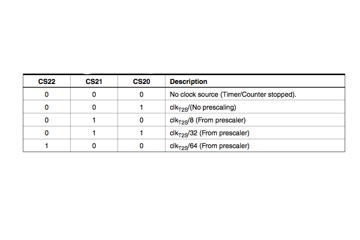
请注意,在最后一步中,不同的计时器有不同的预缩放选项。例如,timer2 没有 1024 预分频器选项。
要在这些定时器中断期间执行的命令位于 Arduino 程序中,封装如下:
ISR(TIMER0_COMPA_vect){ //将 0 更改为 1 表示 timer1,将 2 更改为 timer2
	//中断命令,此处
}
这段代码应位于 setup( )和loop( )函数之外。此外,尽量保持中断例程尽可能短,尤其是在中断频率较高的情况下。甚至值得直接驱动ATMEL芯片的端口/引脚,而不是使用digitalWrite( )和digitalRead( )函数。您可以在此处找到有关此内容的更多信息。
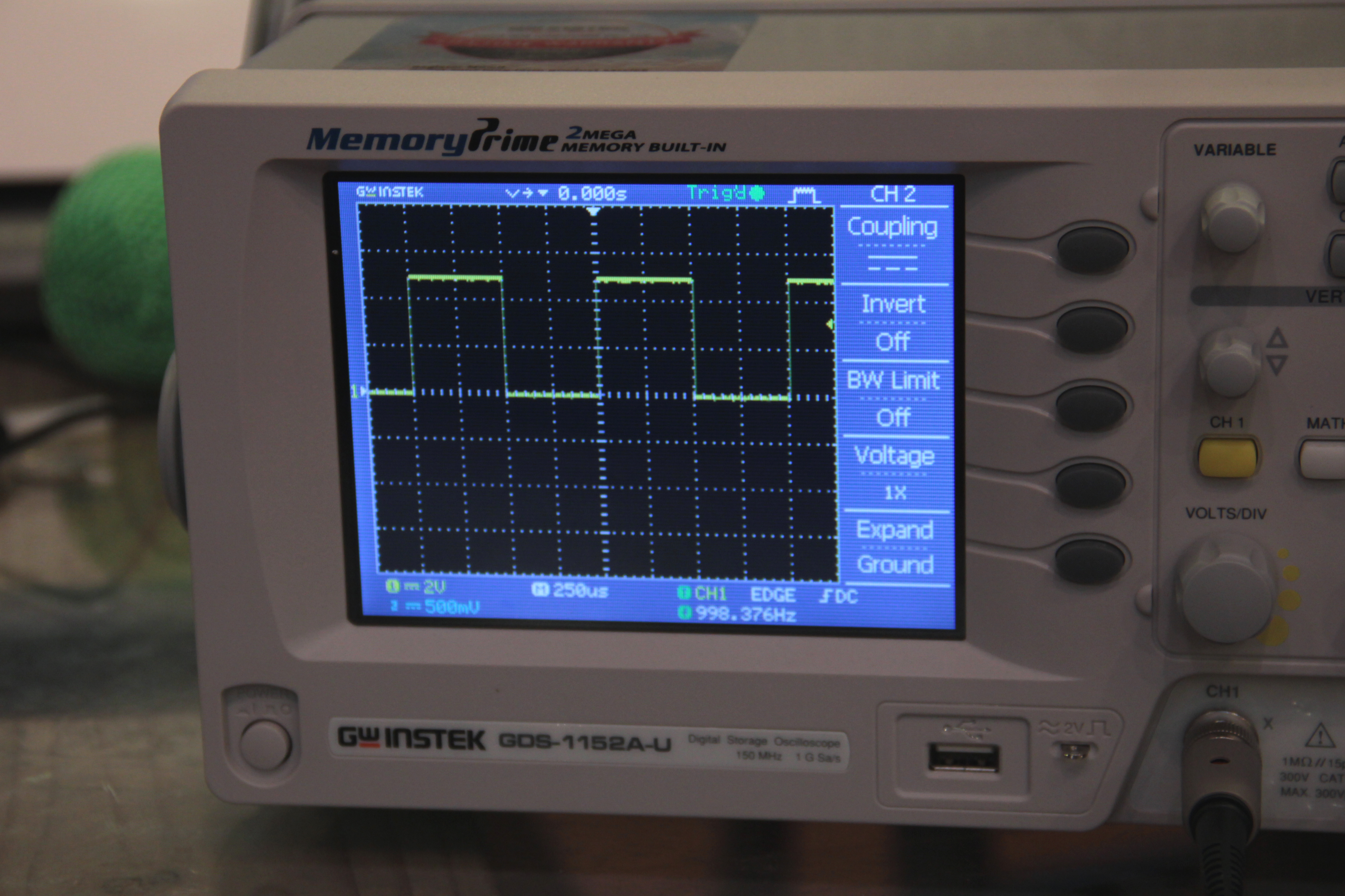
示例 - 下面的程序设置并执行 3 个定时器中断:
上图显示了这些定时器中断的输出。图 1 显示了在 1kHz 时在 0 到 5V 之间振荡的方波(定时器0 中断),图 2 显示了连接到引脚 13 的 LED 导通一秒然后关闭一秒钟(定时器1 中断),图 3 显示了以 4kHz 频率在 0 和 5V 之间振荡的脉冲波(定时器2 中断)。
//https://www.instructables.com/id/Arduino-Timer-Interrupts/

void setup(){

cli();//stop interrupts

//set timer0 interrupt at 2kHz
  TCCR0A = 0;// set entire TCCR0A register to 0
  TCCR0B = 0;// same for TCCR0B
  TCNT0  = 0;//initialize counter value to 0
  // set compare match register for 2khz increments
  OCR0A = 124;// = (16*10^6) / (2000*64) - 1 (must be <256)
  // turn on CTC mode
  TCCR0A |= (1 << WGM01);
  // Set CS01 and CS00 bits for 64 prescaler
  TCCR0B |= (1 << CS01) | (1 << CS00);
  // enable timer compare interrupt
  TIMSK0 |= (1 << OCIE0A);

//set timer1 interrupt at 1Hz
  TCCR1A = 0;// set entire TCCR1A register to 0
  TCCR1B = 0;// same for TCCR1B
  TCNT1  = 0;//initialize counter value to 0
  // set compare match register for 1hz increments
  OCR1A = 15624;// = (16*10^6) / (1*1024) - 1 (must be <65536)
  // turn on CTC mode
  TCCR1B |= (1 << WGM12);
  // Set CS10 and CS12 bits for 1024 prescaler
  TCCR1B |= (1 << CS12) | (1 << CS10);
  // enable timer compare interrupt
  TIMSK1 |= (1 << OCIE1A);

//set timer2 interrupt at 8kHz
  TCCR2A = 0;// set entire TCCR2A register to 0
  TCCR2B = 0;// same for TCCR2B
  TCNT2  = 0;//initialize counter value to 0
  // set compare match register for 8khz increments
  OCR2A = 249;// = (16*10^6) / (8000*8) - 1 (must be <256)
  // turn on CTC mode
  TCCR2A |= (1 << WGM21);
  // Set CS21 bit for 8 prescaler
  TCCR2B |= (1 << CS21);
  // enable timer compare interrupt
  TIMSK2 |= (1 << OCIE2A);


sei();//allow interrupts

}//end setup
//timer interrupts
//by Amanda Ghassaei
//June 2012
//https://www.instructables.com/id/Arduino-Timer-Interrupts/

/*
 * This program is free software; you can redistribute it and/or modify
 * it under the terms of the GNU General Public License as published by
 * the Free Software Foundation; either version 3 of the License, or
 * (at your option) any later version.
 *
*/

//timer setup for timer0, timer1, and timer2.
//For arduino uno or any board with ATMEL 328/168.. diecimila, duemilanove, lilypad, nano, mini...

//this code will enable all three arduino timer interrupts.
//timer0 will interrupt at 2kHz
//timer1 will interrupt at 1Hz
//timer2 will interrupt at 8kHz

//storage variables
boolean toggle0 = 0;
boolean toggle1 = 0;
boolean toggle2 = 0;

void setup(){

  //set pins as outputs
  pinMode(8, OUTPUT);
  pinMode(9, OUTPUT);
  pinMode(13, OUTPUT);

cli();//stop interrupts

//set timer0 interrupt at 2kHz
  TCCR0A = 0;// set entire TCCR2A register to 0
  TCCR0B = 0;// same for TCCR2B
  TCNT0  = 0;//initialize counter value to 0
  // set compare match register for 2khz increments
  OCR0A = 124;// = (16*10^6) / (2000*64) - 1 (must be <256)
  // turn on CTC mode
  TCCR0A |= (1 << WGM01);
  // Set CS01 and CS00 bits for 64 prescaler
  TCCR0B |= (1 << CS01) | (1 << CS00);
  // enable timer compare interrupt
  TIMSK0 |= (1 << OCIE0A);

//set timer1 interrupt at 1Hz
  TCCR1A = 0;// set entire TCCR1A register to 0
  TCCR1B = 0;// same for TCCR1B
  TCNT1  = 0;//initialize counter value to 0
  // set compare match register for 1hz increments
  OCR1A = 15624;// = (16*10^6) / (1*1024) - 1 (must be <65536)
  // turn on CTC mode
  TCCR1B |= (1 << WGM12);
  // Set CS12 and CS10 bits for 1024 prescaler
  TCCR1B |= (1 << CS12) | (1 << CS10);
  // enable timer compare interrupt
  TIMSK1 |= (1 << OCIE1A);

//set timer2 interrupt at 8kHz
  TCCR2A = 0;// set entire TCCR2A register to 0
  TCCR2B = 0;// same for TCCR2B
  TCNT2  = 0;//initialize counter value to 0
  // set compare match register for 8khz increments
  OCR2A = 249;// = (16*10^6) / (8000*8) - 1 (must be <256)
  // turn on CTC mode
  TCCR2A |= (1 << WGM21);
  // Set CS21 bit for 8 prescaler
  TCCR2B |= (1 << CS21);
  // enable timer compare interrupt
  TIMSK2 |= (1 << OCIE2A);


sei();//allow interrupts

}//end setup

ISR(TIMER0_COMPA_vect){//timer0 interrupt 2kHz toggles pin 8
//generates pulse wave of frequency 2kHz/2 = 1kHz (takes two cycles for full wave- toggle high then toggle low)
  if (toggle0){
    digitalWrite(8,HIGH);
    toggle0 = 0;
  }
  else{
    digitalWrite(8,LOW);
    toggle0 = 1;
  }
}

ISR(TIMER1_COMPA_vect){//timer1 interrupt 1Hz toggles pin 13 (LED)
//generates pulse wave of frequency 1Hz/2 = 0.5kHz (takes two cycles for full wave- toggle high then toggle low)
  if (toggle1){
    digitalWrite(13,HIGH);
    toggle1 = 0;
  }
  else{
    digitalWrite(13,LOW);
    toggle1 = 1;
  }
}

ISR(TIMER2_COMPA_vect){//timer1 interrupt 8kHz toggles pin 9
//generates pulse wave of frequency 8kHz/2 = 4kHz (takes two cycles for full wave- toggle high then toggle low)
  if (toggle2){
    digitalWrite(9,HIGH);
    toggle2 = 0;
  }
  else{
    digitalWrite(9,LOW);
    toggle2 = 1;
  }
}


void loop(){
  //do other things here
}
第 3 步:示例 1:自行车车速表
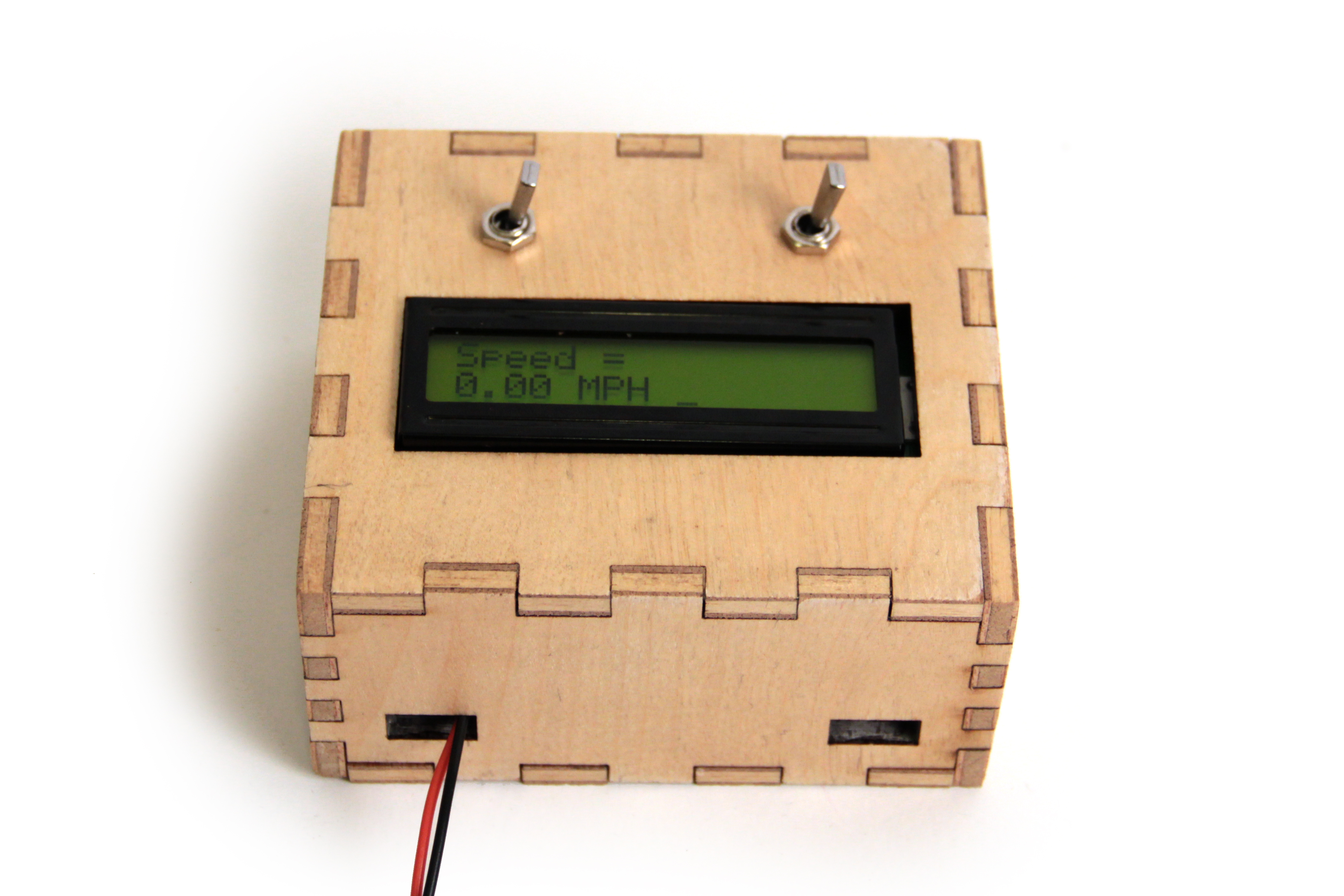
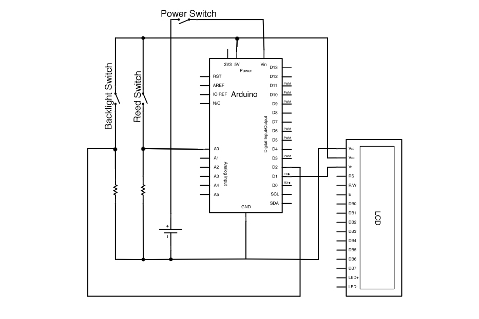

在这个例子中,我做了一个arduino驱动的自行车速度表。它的工作原理是将磁铁连接到车轮上,并测量通过安装在框架上的磁性开关所需的时间 - 车轮完全旋转的时间。
我将定时器1设置为每ms(频率为1kHz)中断一次,以测量磁性开关。如果磁体经过开关,则来自开关的信号为高电平,变量“时间”设置为零。如果磁铁不在开关附近,“时间”将增加 1。这样,“时间”实际上只是自磁铁上次通过磁性开关以来经过的时间量(以毫秒为单位)的度量。此信息稍后在代码中用于计算自行车的转速和英里/小时。
以下是为 1kHz 中断
cli();//stop interrupts
//set timer1 interrupt at 1kHz
TCCR1A = 0;// set entire TCCR1A register to 0
TCCR1B = 0;// same for TCCR1B
TCNT1  = 0;//initialize counter value to 0
// set timer count for 1khz increments
OCR1A = 1999;// = (16*10^6) / (1000*8) - 1
//had to use 16 bit timer1 for this bc 1999>255, but could switch to timers 0 or 2 with larger prescaler
// turn on CTC mode
TCCR1B |= (1 << WGM12);
// Set CS11 bit for 8 prescaler
TCCR1B |= (1 << CS11);
// enable timer compare interrupt
TIMSK1 |= (1 << OCIE1A);
sei();//allow interrupts
如果你想看一下,这里是完整的代码:
//bike speedometer
//by Amanda Ghassaei 2012
//https://www.instructables.com/id/Arduino-Timer-Interrupts/
//https://www.instructables.com/id/Arduino-Timer-Interrupts/

/*
 * This program is free software; you can redistribute it and/or modify
 * it under the terms of the GNU General Public License as published by
 * the Free Software Foundation; either version 3 of the License, or
 * (at your option) any later version.
 *
*/

//sample calculations
//tire radius ~ 13.5 inches
//circumference = pi*2*r =~85 inches
//max speed of 35mph =~ 616inches/second
//max rps =~7.25

#define reed A0//pin connected to read switch

//storage variables
float radius = 13.5;// tire radius (in inches)- CHANGE THIS FOR YOUR OWN BIKE

int reedVal;
long time = 0;// time between one full rotation (in ms)
float mph = 0.00;
float circumference;
boolean backlight;

int maxReedCounter = 100;//min time (in ms) of one rotation (for debouncing)
int reedCounter;


void setup(){

  reedCounter = maxReedCounter;
  circumference = 2*3.14*radius;
  pinMode(1,OUTPUT);//tx
  pinMode(2,OUTPUT);//backlight switch
  pinMode(reed,INPUT);//redd switch

  checkBacklight();

  Serial.write(12);//clear

  // TIMER SETUP- the timer interrupt allows preceise timed measurements of the reed switch
  //for mor info about configuration of arduino timers see http://arduino.cc/playground/Code/Timer1
  cli();//stop interrupts

  //set timer1 interrupt at 1kHz
  TCCR1A = 0;// set entire TCCR1A register to 0
  TCCR1B = 0;// same for TCCR1B
  TCNT1  = 0;//initialize counter value to 0;
  // set timer count for 1khz increments
  OCR1A = 1999;// = (16*10^6) / (1000*8) - 1
  // turn on CTC mode
  TCCR1B |= (1 << WGM12);
  // Set CS11 bit for 8 prescaler
  TCCR1B |= (1 << CS11);
  // enable timer compare interrupt
  TIMSK1 |= (1 << OCIE1A);

  sei();//allow interrupts
  //END TIMER SETUP

  Serial.begin(9600);
}

void checkBacklight(){
  backlight = digitalRead(2);
  if (backlight){
    Serial.write(17);//turn backlight on
  }
  else{
    Serial.write(18);//turn backlight off
  }
}

ISR(TIMER1_COMPA_vect) {//Interrupt at freq of 1kHz to measure reed switch
  reedVal = digitalRead(reed);//get val of A0
  if (reedVal){//if reed switch is closed
    if (reedCounter == 0){//min time between pulses has passed
      mph = (56.8*float(circumference))/float(time);//calculate miles per hour
      time = 0;//reset timer
      reedCounter = maxReedCounter;//reset reedCounter
    }
    else{
      if (reedCounter > 0){//don't let reedCounter go negative
        reedCounter -= 1;//decrement reedCounter
      }
    }
  }
  else{//if reed switch is open
    if (reedCounter > 0){//don't let reedCounter go negative
      reedCounter -= 1;//decrement reedCounter
    }
  }
  if (time > 2000){
    mph = 0;//if no new pulses from reed switch- tire is still, set mph to 0
  }
  else{
    time += 1;//increment timer
  }
}

void displayMPH(){
  Serial.write(12);//clear
  Serial.write("Speed =");
  Serial.write(13);//start a new line
  Serial.print(mph);
  Serial.write(" MPH ");
  //Serial.write("0.00 MPH ");
}

void loop(){
  //print mph once a second
  displayMPH();
  delay(1000);
  checkBacklight();
}
步骤 4:示例 2:串行通信
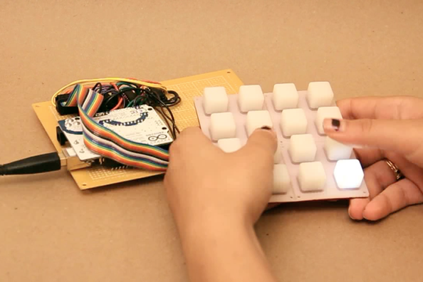
这个项目是一个 4x4 背光按钮垫。该项目通过USB连接到我的计算机,它将有关按钮的信息发送到计算机,并接收有关如何点亮LED的信息。
对于这个项目,我使用 timer2 中断定期检查是否有任何传入的串行数据,读取它,并将其存储在矩阵ledData[]中。如果你看一下代码,你会发现程序的主循环实际上是负责使用 ledData 中的信息来点亮正确的 LED 并检查按钮的状态(一个名为“shift( )”的函数)。中断例程尽可能短 - 只需检查传入字节并适当地存储它们。
这是 timer2
:
cli( );//停止中断/
/每 128us
设置定时器2 中断 TCCR2A = 0;// 将整个 TCCR2A 寄存器设置为 0 TCCR2B = 0;// TCCR2B
TCNT2 = 0;//将计数器值初始化为 0
// 将比较匹配寄存器设置为 7.8khz 增量
OCR2A = 255;// = (16*10^6) / (7812.5*8) - 1(必须为 <256)
// 打开 CTC 模式

TCCR2A |= (1 << WGM21);
将 CS21 位设置为 8 个预分频器
TCCR2B |= (1 << CS21);
启用定时器比较中断
TIMSK2 |= (1 << OCIE2A);
sei( );//allow interrupts
这是完整的 Arduino 程序:
下载下面的MaxMSP补丁(它将在 Max Runtime 中运行)。
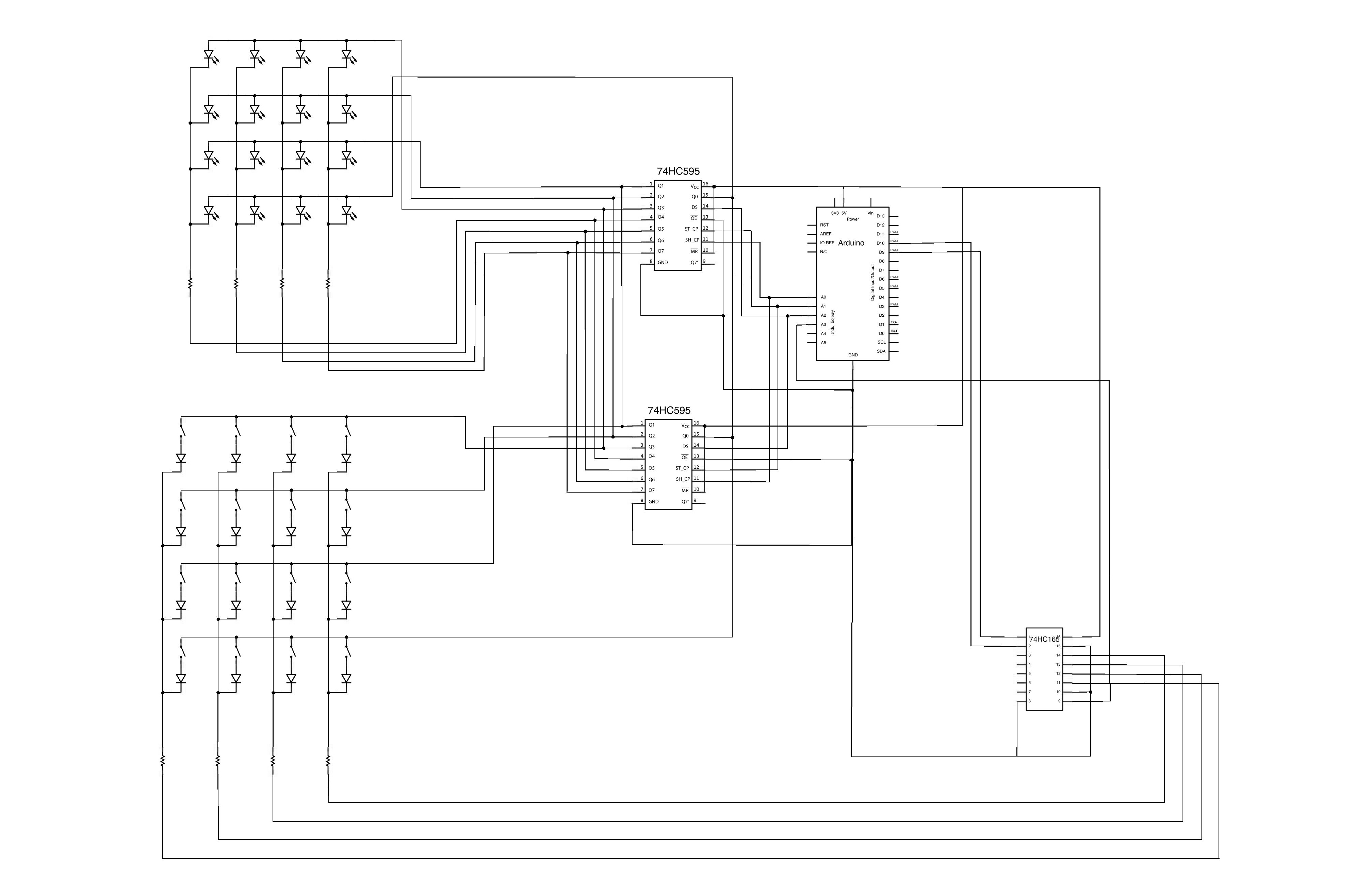
//BUTTON TEST w/ 74HC595 and 74HC165 and serial communication
//by Amanda Ghassaei
//June 2012
//https://www.instructables.com/id/Arduino-Timer-Interrupts/

/*
 * This program is free software; you can redistribute it and/or modify
 * it under the terms of the GNU General Public License as published by
 * the Free Software Foundation; either version 2 of the License, or
 * (at your option) any later version.
 *
*/

//this firmware will send data back and forth with the maxmsp patch "beat slicer"

//pin connections
#define ledLatchPin A1
#define ledClockPin A0
#define ledDataPin A2
#define buttonLatchPin 9
#define buttonClockPin 10
#define buttonDataPin A3

//looping variables
byte i;
byte j;
byte k;
byte ledByte;

//storage for led states, 4 bytes
byte ledData[] = {0, 0, 0, 0};
//storage for buttons, 4 bytes
byte buttonCurrent[] = {0,0,0,0};
byte buttonLast[] = {0,0,0,0};
byte buttonEvent[] = {0,0,0,0};
byte buttonState[] = {0,0,0,0};
//button debounce counter- 16 bytes
byte buttonDebounceCounter[4][4];


void setup() {
  DDRC = 0xF7;//set A0-2 and A4-5 output, A3 input
  DDRB = 0xFF;//digital pins 8-13 output

  Serial.begin(57600);

  cli();//stop interrupts

  //set timer2 interrupt every 128us
  TCCR2A = 0;// set entire TCCR2A register to 0
  TCCR2B = 0;// same for TCCR2B
  TCNT2  = 0;//initialize counter value to 0
  // set compare match register for 7.8khz increments
  OCR2A = 255;// = (16*10^6) / (7812.5*8) - 1 (must be <256)
  // turn on CTC mode
  TCCR2A |= (1 << WGM21);
  // Set CS21 bit for 8 prescaler
  TCCR2B |= (1 << CS21);
  // enable timer compare interrupt
  TIMSK2 |= (1 << OCIE2A);

  sei();//allow interrupts

}

// buttonCheck - checks the state of a given button.
//this buttoncheck function is largely copied from the monome 40h firmware by brian crabtree and joe lake
void buttonCheck(byte row, byte index)
{
  if (((buttonCurrent[row] ^ buttonLast[row]) & (1 << index)) &&   // if the current physical button state is different from the
  ((buttonCurrent[row] ^ buttonState[row]) & (1 << index))) {  // last physical button state AND the current debounced state

    if (buttonCurrent[row] & (1 << index)) {                      // if the current physical button state is depressed
      buttonEvent[row] = 1 << index;              // queue up a new button event immediately
      buttonState[row] |= (1 << index);                         // and set the debounced state to down.
  }
    else{
      buttonDebounceCounter[row][index] = 12;
    }  // otherwise the button was previously depressed and now
    // has been released so we set our debounce counter.
  }
  else if (((buttonCurrent[row] ^ buttonLast[row]) & (1 << index)) == 0 &&  // if the current physical button state is the same as
  (buttonCurrent[row] ^ buttonState[row]) & (1 << index)) {        // the last physical button state but the current physical
    // button state is different from the current debounce
    // state...
    if (buttonDebounceCounter[row][index] > 0 && --buttonDebounceCounter[row][index] == 0) {  // if the the debounce counter has
      // been decremented to 0 (meaning the
      // the button has been up for
      // kButtonUpDefaultDebounceCount
      // iterations///

      buttonEvent[row] = 1 << index;    // queue up a button state change event

      if (buttonCurrent[row] & (1 << index)){          // and toggle the buttons debounce state.
        buttonState[row] |= (1 << index);
      }
      else{
        buttonState[row] &= ~(1 << index);
      }
    }
  }
}


void shift(){

  for (i=0;i<4;i++){

    buttonLast[i] = buttonCurrent[i];

    byte dataToSend = (1 << (i+4)) | (15 & ~ledData[i]);

    // set latch pin low so the LEDs don't change while sending in bits
    digitalWrite(ledLatchPin, LOW);
    // shift out the bits of dataToSend
    shiftOut(ledDataPin, ledClockPin, LSBFIRST, dataToSend);
    //set latch pin high so the LEDs will receive new data
    digitalWrite(ledLatchPin, HIGH);

    //once one row has been set high, receive data from buttons
    //set latch pin high
    digitalWrite(buttonLatchPin, HIGH);
    //shift in data
    buttonCurrent[i] = shiftIn(buttonDataPin, buttonClockPin, LSBFIRST) >> 3;
    //latchpin low
    digitalWrite(buttonLatchPin, LOW);

    for (k=0;k<4;k++){
      buttonCheck(i,k);
      if (buttonEvent[i]<<k){
        if (buttonState[i]&1<<k){
          Serial.write(((3-k)<<3)+(i<<1)+1);
        }
        else{
          Serial.write(((3-k)<<3)+(i<<1)+0);
        }
        buttonEvent[i] &= ~(1<<k);
      }
    }
  }
}


ISR(TIMER2_COMPA_vect) {
  do{
    if (Serial.available()){
      ledByte = Serial.read();//000xxyys
      boolean ledstate = ledByte & 1;
      byte ledy = (ledByte >> 1) & 3;
      byte ledx = (ledByte >> 3) & 3;
      if (ledstate){
        ledData[ledy] |= 8 >> ledx;
      }
      else{
        ledData[ledy] &= ~ (8 >> ledx);
      }
    }//end if serial available
  }//end do
 while (Serial.available() > 8);
}


void loop() {
  shift();//updates leds and receives data from buttons
}
附件
-
[外链图片转存失败,源站可能有防盗链机制,建议将图片保存下来直接上传(img-9XNO6mE9-1670401333680)(https://content.instructables.com/static/image/file.default.gif)]beat slicer.zip
下载
步骤 5:示例 3:DAC
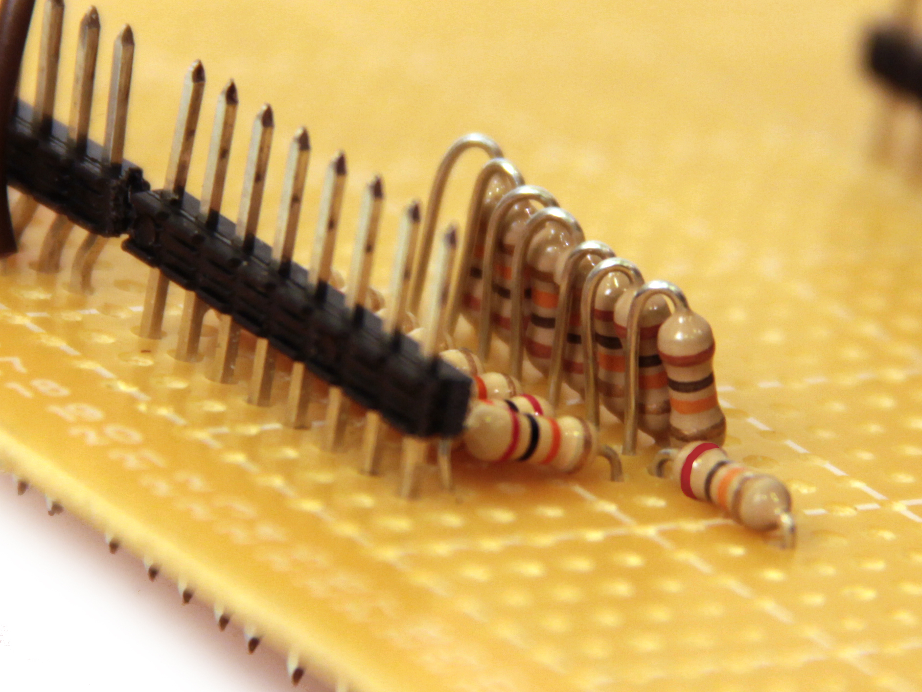
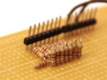
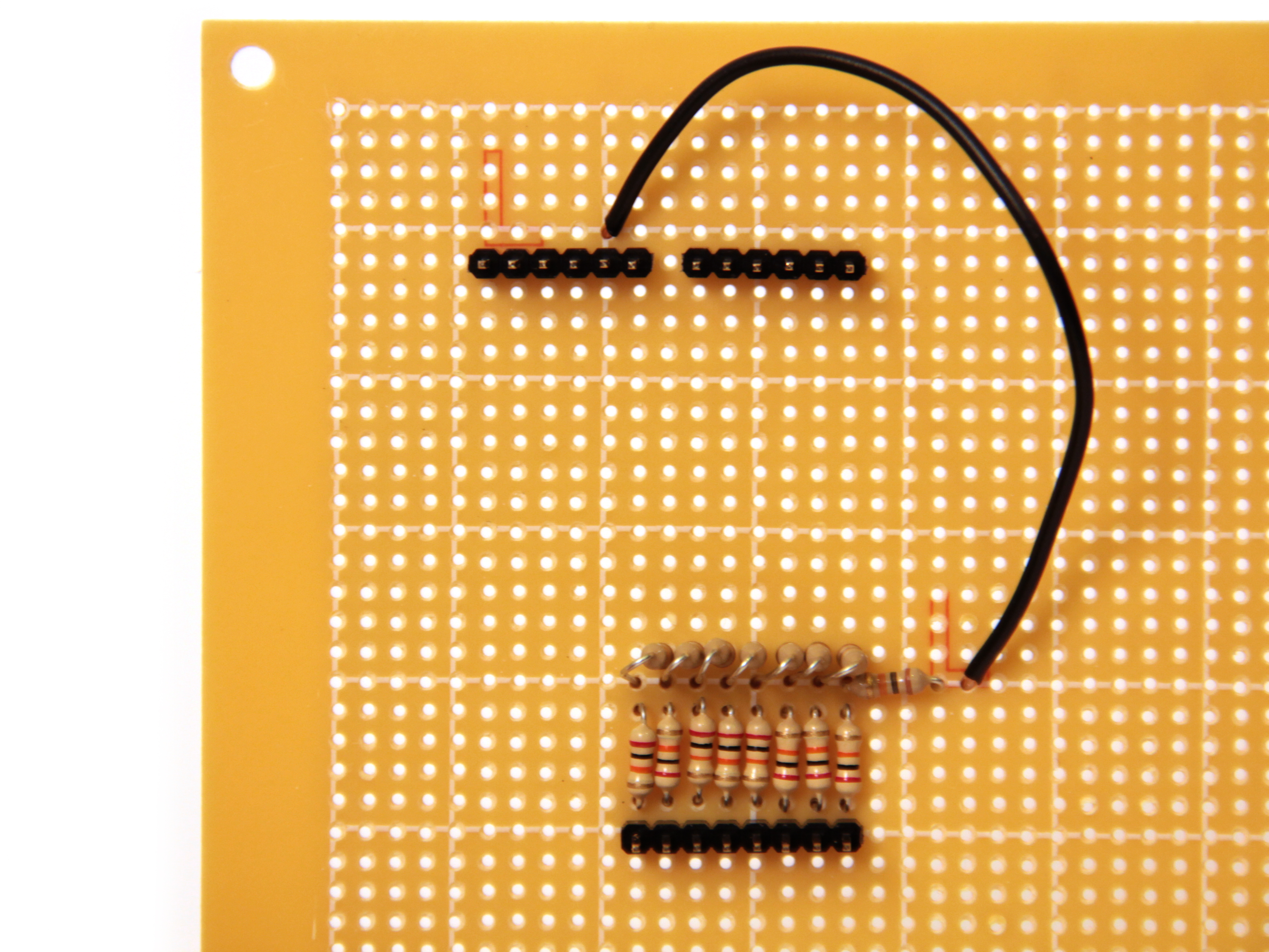
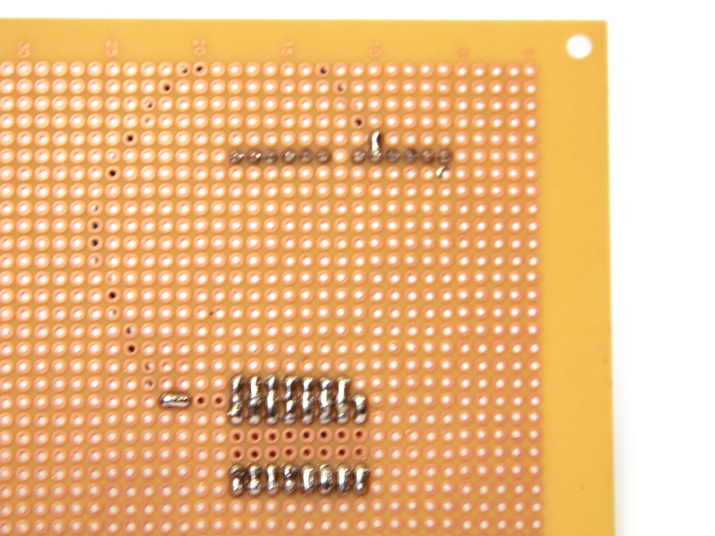
在这个项目中,我使用定时器中断从Arduino输出特定频率的正弦波。我将一个简单的8位R2R DAC焊接到数字引脚0-7上。该DAC由排列在多电平分压器中的10k和20k电阻构成。我将在另一个指导中发布更多关于DAC结构的信息,现在我已经包含了上面的照片。
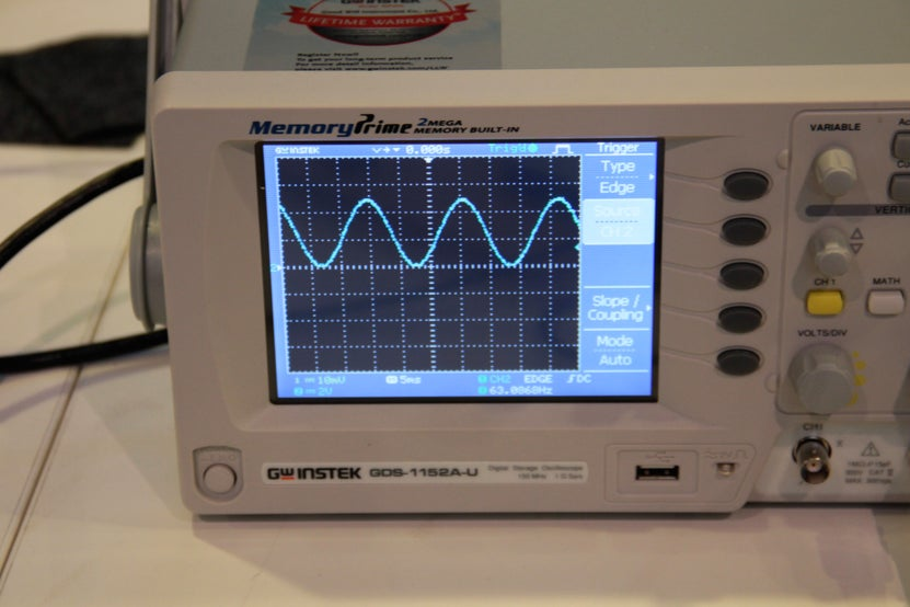
我将DAC的输出连接到示波器。如果您需要了解如何使用/阅读示波器的帮助,请查看本教程。我将以下代码加载到Arduino上:
我设置了一个定时器中断,以40kHz的频率递增变量t。一旦 t 达到 627,它就会重置为零(频率为 40,000/628 = 63Hz)。同时,在主循环中,Arduino 将介于 0(二进制为 00000000)和 255(二进制为 11111111)之间的值发送到数字引脚 0 到 7(PORTD)。它使用以下公式计算此值:
P O R T D = b y t e ( 127 + 127 ∗ sin ( t / 100 ) ) PORTD=byte(127+127*\sin{(t/100)}) PORTD=byte(127+127∗sin(t/100))
因此,当 t 从 0 递增到 627 时,正弦函数将经历一个完整的周期。发送到 PORTD 的值是一个频率为 63Hz、振幅为 127 的正弦波,振荡在 127 左右。当它通过8位电阻梯形DAC发送时,它输出一个大约2.5V的振荡信号,幅度为2.5V,频率为63Hz.
正弦波的频率可以通过将(t/100)项乘以2来加倍,乘以4可以翻倍,依此类推…
另请注意,如果通过减少预分频器或 OCR2A 来过多地增加定时器中断的频率,则正弦波将无法正确输出。这是因为 sin( )函数的计算成本很高,并且在高中断频率下它没有足够的时间来执行。如果使用高频中断,请考虑将值存储在数组中并简单地使用某种索引调用这些值,而不是在中断例程期间执行计算。您可以在我的arduino 波形发生器中找到一个例子 - 通过在数组中存储 20,000 个 sin 值,我能够以 100kHz 的采样频率输出正弦波。
第 6 步:定时器和 Arduino 函数
最后要注意的一件事 - 某些计时器设置实际上会禁用某些Arduino库功能。Timer0 由函数millis() 和delay( ) 使用,如果您手动设置 timer0,这些函数将无法正常工作。
此外,所有三个计时器都支持函数 analogWrite( )。手动设置计时器将阻止 analogWrite( )工作。
如果代码的某些部分不想中断,请考虑使用 cli( )和sei( )全局禁用和启用中断。
您可以在Arduino网站上阅读有关此内容的更多信息。