工程搭建参考:https://blog.csdn.net/feisy/article/details/126380289
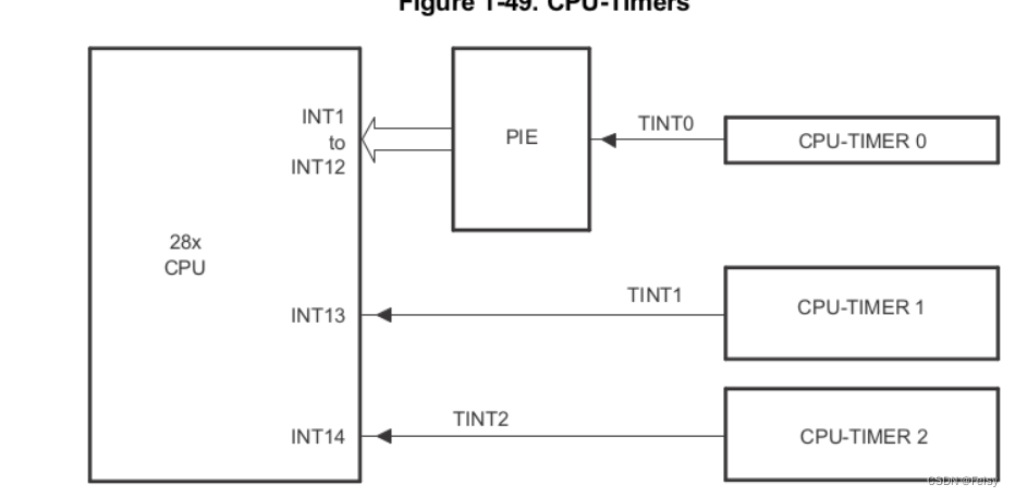
F28069有三个32位的CPU定时器:0,1,2。0,1可用,如果程序未使用DIS/BIOS,定时器2也可用。
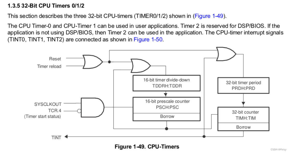
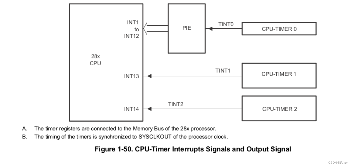
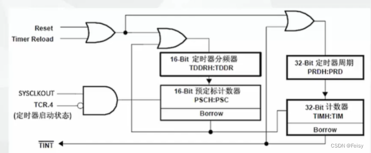
CPU定时器相关的有5个信号,四个输入信号,一个输出信号
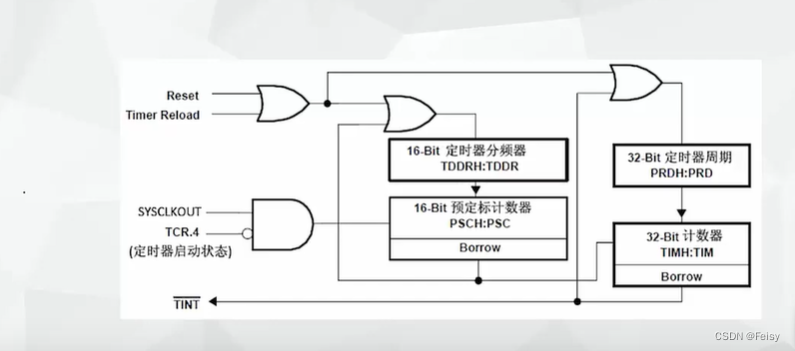
- Reset信号:复位信号,给定时器复位用的
- Timer reload:定时器重载信号,控制定时器要不要重新装载周期计算器
- SYSCLKOUT:系统时钟信号
- TCR.4=TCR.bit.4.TSS:控制定时器计时开始或者停止
- TINT:输出信息,周期中断
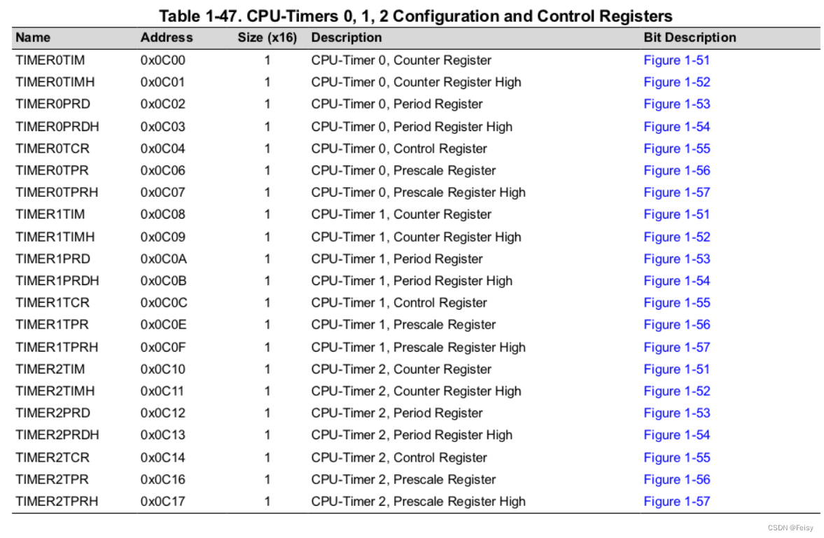
CPU定时器涉及的寄存器
- TDDR :定时器减一的时间长度,两个16位的寄存器表示
- PRD:设置CPU定时器的周期,两个16位的寄存器表示
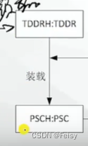
- PSC开始计数时,会将TDDR 装载到这里,用来不断自减减到0,到0会产生TIMCLK信号,让TIM减一
- TIM:开始计数时,会将PRD 装载到这里,用来不断自减,,会产生一个中断信号,这时会回调定时器中断函数
- TPR:F28069里跟TDDR功能一样的寄存器?
- TCR:装载,启用或者停止定时器的寄存器:TCR.bit.TSS = 1(1 = Stop timer, 0 = Start/Restart Timer),TCR.bit.TRB = 1( 1 = reload timer),TCR.bit.TIE = 1( 0 = Disable/ 1 = Enable Timer Interrupt)
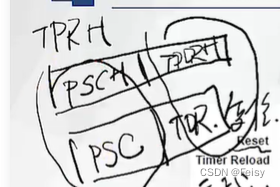
定时器的寄存器的形式是XH:X这样的形式,后半部分X表示低位,前半部分XH表示高位
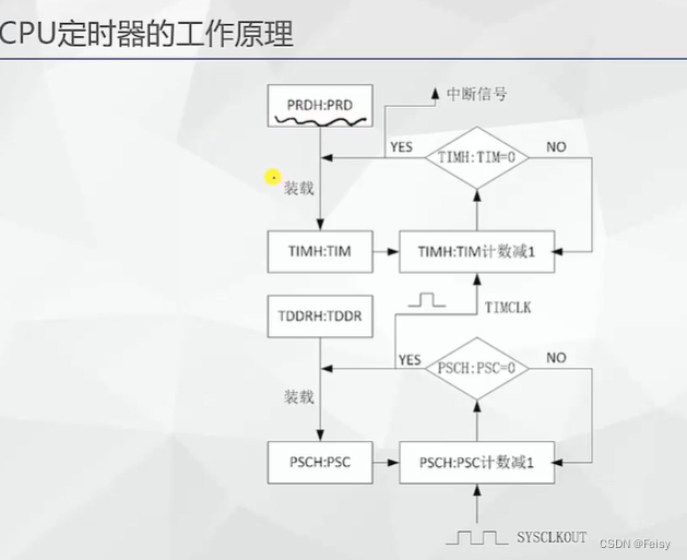
#CPU定时器的工作原理
-
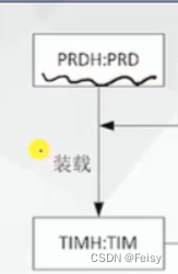
给CPU周期寄存器赋值

-
开始计数时,CPU会将计数值装在到TIM寄存器
-
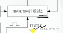
每个一个TIMCLK,TIM会不断减一,一直减到0
-
减到0,完成一个定时周期,会产生一个中断
.
TIMCLK代表是了计数器减一的时间长度,它是通过定时器 的分频寄存器TDDR来设置的
计数时,TIMCLK会被装载到PSC寄存器
PSC里面的数值在每个SYSCLK都会减一,减到0时,会产生一个让TIMCLK减一的信号
一个计算例子
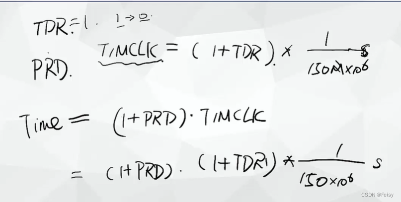
PDR会被装载到PSC,每个SYSCLK都会减一,减到0时,会产生一个让TIMCLK减一的信号,TIMCLK=(1+PDR)个SYSCLKOUT,以F28335为例,主频是150M,TIMCLK=(1+PDR)*(1/150M)秒
一个周期是 (1+PRD) * TIMCLK
代码演示,通过定时器来控制LED闪烁
1 设置定时器的回调函数
注意,TINT0是在PIE TABLE的第7位,后面还有关于启用第一组,以及启用第7个中断的设置
// Interrupts that are used in this example are re-mapped to
// ISR functions found within this file.
   EALLOW;  // This is needed to write to EALLOW protected registers
   PieVectTable.TINT0 = &cpu_timer0_isr;

   EDIS;    // This is needed to disable write to EALLOW protected registers
2 获取定时器寄存器, 配置定时器的一些默认值
使用到的一个函数
void InitCpuTimers(void)
{
    // CPU Timer 0
	// Initialize address pointers to respective timer registers:
	CpuTimer0.RegsAddr = &CpuTimer0Regs;
	// Initialize timer period to maximum:
	CpuTimer0Regs.PRD.all  = 0xFFFFFFFF;//PRD寄存器设置CPU定时器的周期,两个16位的寄存器表示,这里设置到最大
	//TPR寄存器的作用是CPU会在(TPR[TDDRH:TDDR]+1)个SYSCLOUT后,将TIM减一,这里置0,表示,每个SYSCLKOUT都会让TIM减一
	// Initialize pre-scale counter to divide by 1 (SYSCLKOUT):
	//The 32-bit counter register TIMH:TIM is loaded with
	//the value in the period register PRDH:PRD. The counter decrements once every (TPR[TDDRH:TDDR]+1)SYSCLKOUT cycles, where TDDRH:TDDR is the timer divider.

	CpuTimer0Regs.TPR.all  = 0;
	CpuTimer0Regs.TPRH.all = 0;
	// Make sure timer is stopped:
	CpuTimer0Regs.TCR.bit.TSS = 1;//TSS=0表示定时器停止
	// Reload all counter register with period value:
	CpuTimer0Regs.TCR.bit.TRB = 1;
	// Reset interrupt counters:
	//CpuTimer0.InterruptCount = 0;


// Initialize address pointers to respective timer registers:
	CpuTimer1.RegsAddr = &CpuTimer1Regs;
	CpuTimer2.RegsAddr = &CpuTimer2Regs;
	// Initialize timer period to maximum:
	CpuTimer1Regs.PRD.all  = 0xFFFFFFFF;
	CpuTimer2Regs.PRD.all  = 0xFFFFFFFF;
    // Initialize pre-scale counter to divide by 1 (SYSCLKOUT):
	CpuTimer1Regs.TPR.all  = 0;
	CpuTimer1Regs.TPRH.all = 0;
	CpuTimer2Regs.TPR.all  = 0;
	CpuTimer2Regs.TPRH.all = 0;
    // Make sure timers are stopped:
	CpuTimer1Regs.TCR.bit.TSS = 1;
	CpuTimer2Regs.TCR.bit.TSS = 1;
	// Reload all counter register with period value:
	CpuTimer1Regs.TCR.bit.TRB = 1;
	CpuTimer2Regs.TCR.bit.TRB = 1;
	// Reset interrupt counters:
	//CpuTimer1.InterruptCount = 0;
	//CpuTimer2.InterruptCount = 0;

}
3 设置定时器的长度
因为F28069的主频是80M,所以我们设置定时器的周期步数是80,每一步是1000000,即1000000个SYSCLKOUT,定时器减一。
// Configure CPU-Timer 0, 1, and 2 to interrupt every second:
// 80MHz CPU Freq, 1 second Period (in uSeconds)

   ConfigCpuTimer(&CpuTimer0, 80, 1000000);
void ConfigCpuTimer(struct CPUTIMER_VARS *Timer, float Freq, float Period)
{
	Uint32 	PeriodInClocks;

	// Initialize timer period:
	Timer->CPUFreqInMHz = Freq;
	Timer->PeriodInUSec = Period;
	PeriodInClocks = (long) (Freq * Period);
	//设置CPU定时器的周期,
	Timer->RegsAddr->PRD.all = PeriodInClocks - 1; // Counter decrements PRD+1 times each period

	//这里这样的设置是每个SYSCLKOUT,都会产生一个TIMCLK,让其减一
	// Set pre-scale counter to divide by 1 (SYSCLKOUT):
	Timer->RegsAddr->TPR.all  = 0;
	Timer->RegsAddr->TPRH.all  = 0;

	// Initialize timer control register:
	Timer->RegsAddr->TCR.bit.TSS = 1;      // 1 = Stop timer, 0 = Start/Restart Timer
	Timer->RegsAddr->TCR.bit.TRB = 1;      // 1 = reload timer
	Timer->RegsAddr->TCR.bit.SOFT = 0;
	Timer->RegsAddr->TCR.bit.FREE = 0;     // Timer Free Run Disabled
	Timer->RegsAddr->TCR.bit.TIE = 1;      // 0 = Disable/ 1 = Enable Timer Interrupt

	// Reset interrupt counter:
	Timer->InterruptCount = 0;

}
4 启用定时器
	//TCR.bit.TSS = 0表示启动寄存器
   CpuTimer0Regs.TCR.all = 0x4000; // Use write-only instruction to set TSS bit = 0
5 启用 中断向量表的第一组
    //
    // Enable CPU INT1 which is connected to CPU-Timer 0
    //
    IER |= M_INT1;
6 启用 中断向量表的第一组的第7个中断
    //
    // Enable TINT0 in the PIE: Group 1 interrupt 7
    //
    PieCtrlRegs.PIEIER1.bit.INTx7 = 1;
7 打开全局中断
// Enable global Interrupts and higher priority real-time debug events:
   EINT;   // Enable Global interrupt INTM
   ERTM;   // Enable Global realtime interrupt DBGM
5 完整代码
//###########################################################################
//
// FILE:   Example_2806xLEDBlink.c
//
// TITLE:  Timer based blinking LED Example
//
//!  \addtogroup f2806x_example_list
//!  <h1>Timer based blinking LED(timed_led_blink)</h1>
//!
//!  This example configures CPU Timer0 for a 500 msec period, and toggles the
//!  GPIO34 LED once per interrupt. For testing purposes, this example
//!  also increments a counter each time the timer asserts an interrupt.
//!
//!  \b Watch \b Variables \n
//!  - CpuTimer0.InterruptCount
//!
//! \b External \b Connections \n
//!  Monitor the GPIO34 LED blink on (for 500 msec) and off (for 500 msec) on
//!  the 2806x control card.
//
//###########################################################################
// $TI Release:  $
// $Release Date:  $
// $Copyright:
// Copyright (C) 2009-2022 Texas Instruments Incorporated - http://www.ti.com/
//
// Redistribution and use in source and binary forms, with or without
// modification, are permitted provided that the following conditions
// are met:
//
//   Redistributions of source code must retain the above copyright
//   notice, this list of conditions and the following disclaimer.
//
//   Redistributions in binary form must reproduce the above copyright
//   notice, this list of conditions and the following disclaimer in the
//   documentation and/or other materials provided with the
//   distribution.
//
//   Neither the name of Texas Instruments Incorporated nor the names of
//   its contributors may be used to endorse or promote products derived
//   from this software without specific prior written permission.
//
// THIS SOFTWARE IS PROVIDED BY THE COPYRIGHT HOLDERS AND CONTRIBUTORS
// "AS IS" AND ANY EXPRESS OR IMPLIED WARRANTIES, INCLUDING, BUT NOT
// LIMITED TO, THE IMPLIED WARRANTIES OF MERCHANTABILITY AND FITNESS FOR
// A PARTICULAR PURPOSE ARE DISCLAIMED. IN NO EVENT SHALL THE COPYRIGHT
// OWNER OR CONTRIBUTORS BE LIABLE FOR ANY DIRECT, INDIRECT, INCIDENTAL,
// SPECIAL, EXEMPLARY, OR CONSEQUENTIAL DAMAGES (INCLUDING, BUT NOT
// LIMITED TO, PROCUREMENT OF SUBSTITUTE GOODS OR SERVICES; LOSS OF USE,
// DATA, OR PROFITS; OR BUSINESS INTERRUPTION) HOWEVER CAUSED AND ON ANY
// THEORY OF LIABILITY, WHETHER IN CONTRACT, STRICT LIABILITY, OR TORT
// (INCLUDING NEGLIGENCE OR OTHERWISE) ARISING IN ANY WAY OUT OF THE USE
// OF THIS SOFTWARE, EVEN IF ADVISED OF THE POSSIBILITY OF SUCH DAMAGE.
// $
//###########################################################################

//
// Included Files
//
#include "DSP28x_Project.h"     // Device Headerfile and Examples Include File

//
// Function Prototypes statements for functions found within this file.
//
__interrupt void cpu_timer0_isr(void);

//
// Main
//
void main(void)
{
    //
    // Step 1. Initialize System Control:
    // PLL, WatchDog, enable Peripheral Clocks
    // This example function is found in the F2806x_SysCtrl.c file.
    //
    InitSysCtrl();

    //
    // Step 2. Initalize GPIO:
    // This example function is found in the F2806x_Gpio.c file and
    // illustrates how to set the GPIO to it's default state.
    //
//    InitGpio();  // Skipped for this example

    //
    // Step 3. Clear all interrupts and initialize PIE vector table:
    // Disable CPU interrupts
    //
    DINT;

    //
    // Initialize the PIE control registers to their default state.
    // The default state is all PIE interrupts disabled and flags
    // are cleared.
    // This function is found in the F2806x_PieCtrl.c file.
    //
    InitPieCtrl();

    //
    // Disable CPU interrupts and clear all CPU interrupt flags
    //
    IER = 0x0000;
    IFR = 0x0000;

    //
    // Initialize the PIE vector table with pointers to the shell Interrupt
    // Service Routines (ISR).
    // This will populate the entire table, even if the interrupt
    // is not used in this example.  This is useful for debug purposes.
    // The shell ISR routines are found in F2806x_DefaultIsr.c.
    // This function is found in F2806x_PieVect.c.
    //
    InitPieVectTable();

    //
    // Interrupts that are used in this example are re-mapped to
    // ISR functions found within this file.
    //
    EALLOW;    // This is needed to write to EALLOW protected registers
    PieVectTable.TINT0 = &cpu_timer0_isr;
    EDIS;      // This is needed to disable write to EALLOW protected registers

    //
    // Step 4. Initialize the Device Peripheral. This function can be
    //         found in F2806x_CpuTimers.c
    //
    InitCpuTimers();   // For this example, only initialize the Cpu Timers

    //
    // Configure CPU-Timer 0 to interrupt every 500 milliseconds:
    // 80MHz CPU Freq, 50 millisecond Period (in uSeconds)
    //
    ConfigCpuTimer(&CpuTimer0, 80, 500000);

    //
    // To ensure precise timing, use write-only instructions to write to the
    // entire register. Therefore, if any of the configuration bits are changed
    // in ConfigCpuTimer and InitCpuTimers (in F2806x_CpuTimers.h), the
    // below settings must also be updated.
    //

    //
    // Use write-only instruction to set TSS bit = 0
    //
    CpuTimer0Regs.TCR.all = 0x4001;

    //
    // Step 5. User specific code, enable interrupts:
    //

    //
    // Configure GPIO34 as a GPIO output pin
    //
    EALLOW;
    GpioCtrlRegs.GPBMUX1.bit.GPIO34 = 0;
    GpioCtrlRegs.GPBDIR.bit.GPIO34 = 1;
    EDIS;

    //
    // Enable CPU INT1 which is connected to CPU-Timer 0
    //
    IER |= M_INT1;

    //
    // Enable TINT0 in the PIE: Group 1 interrupt 7
    //
    PieCtrlRegs.PIEIER1.bit.INTx7 = 1;

    //
    // Enable global Interrupts and higher priority real-time debug events
    //
    EINT;   // Enable Global interrupt INTM
    ERTM;   // Enable Global realtime interrupt DBGM

    //
    // Step 6. IDLE loop. Just sit and loop forever (optional)
    //
    for(;;);
}

//
// cpu_timer0_isr -
//
__interrupt void
cpu_timer0_isr(void)
{
    CpuTimer0.InterruptCount++;

    //
    // Toggle GPIO34 once per 500 milliseconds
    //
    //我之前一直用软件的角度去看代码,以为这个是赋值的意思,但其实这个是硬件中的GPIO的翻转操作
    //,即每次=1,会让GPIO的电平发生变化,变到另外一个状态。
    //比如,原先是高电平,执行一次=1,就变成了低电平了。。。。
    GpioDataRegs.GPBTOGGLE.bit.GPIO34 = 1;

    //
    // Acknowledge this interrupt to receive more interrupts from group 1
    //
    PieCtrlRegs.PIEACK.all = PIEACK_GROUP1;
}

//
// End of File
//
![[激光原理与应用-37]:《光电检测技术-4》- 光学测量基础 - 噪声与光学中的常见电路](https://img-blog.csdnimg.cn/33a386a5161a4f6db8816f0f8e66007e.png)
![[附源码]计算机毕业设计数字乡村基础治理系统Springboot程序](https://img-blog.csdnimg.cn/6a451369471d4ce4a5278f2ea0b7a121.png)

![[Mysql]数据库约束](https://img-blog.csdnimg.cn/045859dcb98a426c9dbb10fdce5ece20.png)